CS 62
CONVERTITORE
STATICO DI TENSIONE
ALTERNATA
Isolato galvanicamente
(1500 Vac, 1min)
ALTERNATE
VOLTAGE
TRANSDUCER
Galvanic insulation (1500 Vac, 1 min)
REMARK 1:
Interchangeable with E 262 by changing the connections on the male
base.
NOTA 1:
Intercambiabile con E 262 cambiando
i collegamenti sullo zoccolo.
DEFINIZIONE
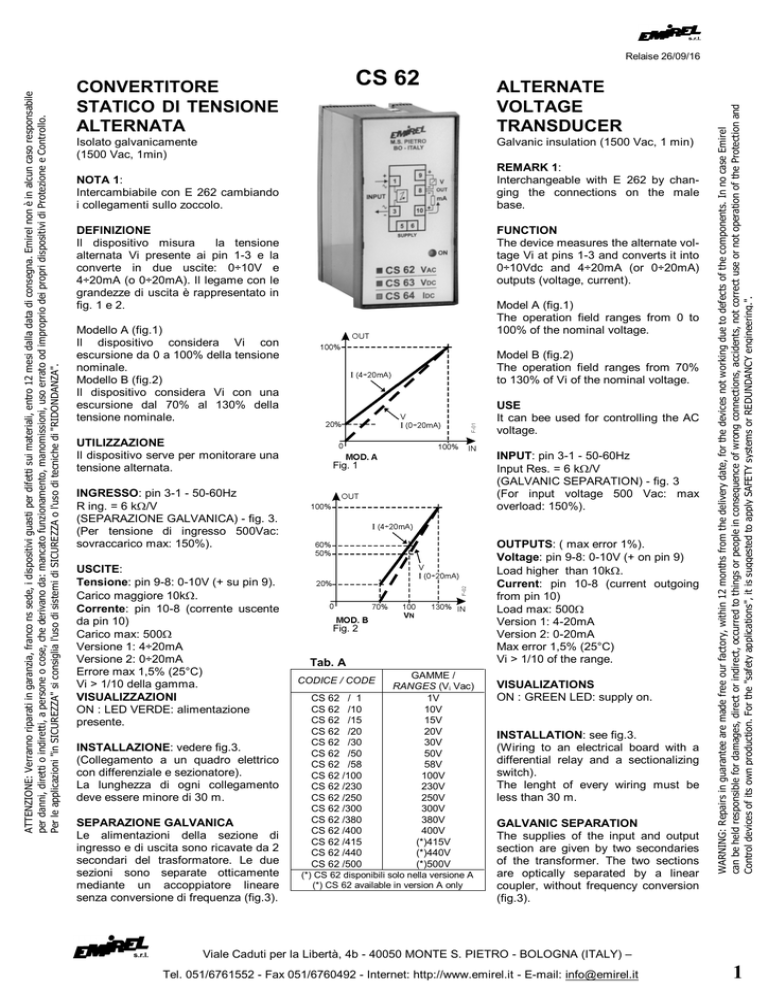
Il dispositivo misura
la tensione
alternata Vi presente ai pin 1-3 e la
converte in due uscite: 0÷10V e
4÷20mA (o 0÷20mA). Il legame con le
grandezze di uscita è rappresentato in
fig. 1 e 2.
FUNCTION
The device measures the alternate voltage Vi at pins 1-3 and converts it into
0÷10Vdc and 4÷20mA (or 0÷20mA)
outputs (voltage, current).
Model A (fig.1)
The operation field ranges from 0 to
100% of the nominal voltage.
Modello A (fig.1)
Il dispositivo considera Vi con
escursione da 0 a 100% della tensione
nominale.
Modello B (fig.2)
Il dispositivo considera Vi con una
escursione dal 70% al 130% della
tensione nominale.
UTILIZZAZIONE
Il dispositivo serve per monitorare una
tensione alternata.
Model B (fig.2)
The operation field ranges from 70%
to 130% of Vi of the nominal voltage.
USE
It can bee used for controlling the AC
voltage.
INPUT: pin 3-1 - 50-60Hz
Input Res. = 6 k/V
(GALVANIC SEPARATION) - fig. 3
(For input voltage 500 Vac: max
overload: 150%).
Fig. 1
INGRESSO: pin 3-1 - 50-60Hz
R ing. = 6 k/V
(SEPARAZIONE GALVANICA) - fig. 3.
(Per tensione di ingresso 500Vac:
sovraccarico max: 150%).
USCITE:
Tensione: pin 9-8: 0-10V (+ su pin 9).
Carico maggiore 10k.
Corrente: pin 10-8 (corrente uscente
da pin 10)
Carico max: 500
Versione 1: 4÷20mA
Versione 2: 0÷20mA
Errore max 1,5% (25°C)
Vi > 1/10 della gamma.
VISUALIZZAZIONI
ON : LED VERDE: alimentazione
presente.
INSTALLAZIONE: vedere fig.3.
(Collegamento a un quadro elettrico
con differenziale e sezionatore).
La lunghezza di ogni collegamento
deve essere minore di 30 m.
SEPARAZIONE GALVANICA
Le alimentazioni della sezione di
ingresso e di uscita sono ricavate da 2
secondari del trasformatore. Le due
sezioni sono separate otticamente
mediante un accoppiatore lineare
senza conversione di frequenza (fig.3).
OUTPUTS: ( max error 1%).
Voltage: pin 9-8: 0-10V (+ on pin 9)
Load higher than 10k.
Current: pin 10-8 (current outgoing
from pin 10)
Load max: 500
Version 1: 4-20mA
Version 2: 0-20mA
Max error 1,5% (25°C)
Vi > 1/10 of the range.
Fig. 2
Tab. A
CODICE / CODE
CS 62 / 1
CS 62 /10
CS 62 /15
CS 62 /20
CS 62 /30
CS 62 /50
CS 62 /58
CS 62 /100
CS 62 /230
CS 62 /250
CS 62 /300
CS 62 /380
CS 62 /400
CS 62 /415
CS 62 /440
CS 62 /500
GAMME /
RANGES (Vi Vac)
1V
10V
15V
20V
30V
50V
58V
100V
230V
250V
300V
380V
400V
(*)415V
(*)440V
(*)500V
(*) CS 62 disponibili solo nella versione A
(*) CS 62 available in version A only
VISUALIZATIONS
ON : GREEN LED: supply on.
INSTALLATION: see fig.3.
(Wiring to an electrical board with a
differential relay and a sectionalizing
switch).
The lenght of every wiring must be
less than 30 m.
GALVANIC SEPARATION
The supplies of the input and output
section are given by two secondaries
of the transformer. The two sections
are optically separated by a linear
coupler, without frequency conversion
(fig.3).
WARNING: Repairs in guarantee are made free our factory, within 12 months from the delivery date, for the devices not working due to defects of the components. In no case Emirel
can be held responsible for damages, direct or indirect, occurred to things or people in consequence of wrong connections, accidents, not correct use or not operation of the Protection and
Control devices of its own production. For the "safety applications", it is suggested to apply SAFETY systems or REDUNDANCY engineering.".
ATTENZIONE: Verranno riparati in garanzia, franco ns sede, i dispositivi guasti per difetti sui materiali, entro 12 mesi dalla data di consegna. Emirel non è in alcun caso responsabile
per danni, diretti o indiretti, a persone o cose, che derivano da: mancato funzionamento, manomissioni, uso errato od improprio dei propri dispositivi di Protezione e Controllo.
Per le applicazioni "in SICUREZZA" si consiglia l'uso di sistemi di SICUREZZA o l'uso di tecniche di "RIDONDANZA".
Relaise 26/09/16
Viale Caduti per la Libertà, 4b - 40050 MONTE S. PIETRO - BOLOGNA (ITALY) –
Tel. 051/6761552 - Fax 051/6760492 - Internet: http://www.emirel.it - E-mail: [email protected]
1
RISPOSTA AL GRADINO
(10%÷90%) < 360 msec
STEP RESPONSE
(10%÷90%) < 360 msec
ALIMENTAZIONE: 2VA - 50-60Hz
Tolleranza: ±10%
Pin 5-6: 24 Vac o 230 Vac
SUPPLY: 2VA - 50-60Hz Tolerance: ±10%
Pin 5-6: 24 Vac or 230 Vac
DIMENSIONI: 48x96x90 mm
innesto per zoccolo undecal.
con
Accessori disponibili a richiesta:
E 171: ganci per montaggio da
incasso.
E 172: zoccolo femm. undecal per DIN
M 13A: protezione plexiglas
piombabile IP54.
E 346:molle di sostegno
antisfilamento
Dima di Foratura 45x92 mm
SIZE: 48x96x90 mm undecal male base.
Fig. 3
COMPATIBILITA' ELETTRO
MAGNETICA
Electromagnetic compatibility
CEI-EN 61326-1
“BASSA TENSIONE” - LVD
LVD – “LOW VOLTAGE”
PESO: 0,230 kg
Accessories available on request:
E 171 : hooks for flush mounting.
E 172 : undecal female base for DIN.
M 13A: plexiglas protection IP 54-tight
closure.
E 346 : hold spring protecting from
vibrations.
Template: 45x92 mm
WEIGHT: 0,230 kg
CEI-EN 61010-1
COLORE: nero
TEMP.
0÷70°C
DI
COLOUR: black
FUNZIONAMENTO:
Per la pulizia usare un panno imbevuto
di detergenti privi di: Alcool denaturato,
Benzene, Alcool isopropilico.
Nota generale: Negli schemi di
collegamento non sono riportati i fusibili
sulle alimentazioni e sugli ingressi
voltmetrici.
I collegamenti elettrici devono essere
eseguiti a dispositivo e quadro elettrico
spenti.
WORKING TEMPERATURE: 0÷70°C
For cleaning use a cloth soaked with
detergents without: Denatured Alcohol,
Benzene, Isopropyl alcohol.
General remark: The wiring
diagrammes do not show the fuses
installed on the supply and on the
voltmetric inputs.
The electric wirings must be realized
with device and electrical panel in off
condition.
Viale Caduti per la Libertà, 4b - 40050 MONTE S. PIETRO - BOLOGNA (ITALY) –
2
Tel. 051/6761552 - Fax 051/6760492 - Internet: http://www.emirel.it - E-mail: [email protected]

