16/12/14
RELEASE:
CONVERTITORE
STATICO DI
FATTORE DI POTENZA
E 425
POWER FACTOR
STATIC TRANSDUCER
DEFINIZIONE e UTILIZZO
Il dispositivo misura il FATTORE DI
POTENZA in una rete monofase o in una
rete trifase (a 3 fili, con carico equilibrato).
FUNCTION and USE
The device measures the POWER FACTOR in a single or three phase mains
(three wires, balanced load).
CARATTERISTICHE E
REGOLAZIONI
TECHNICAL FEATURES AND
REGULATIONS
Versione A
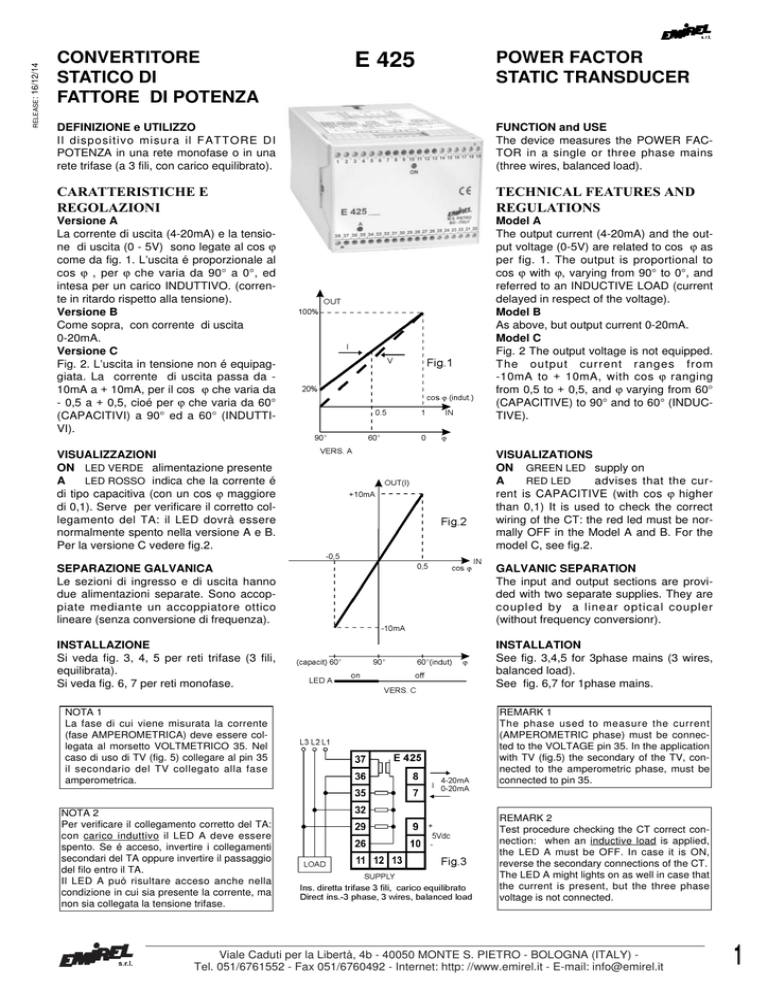
La corrente di uscita (4-20mA) e la tensione di uscita (0 - 5V) sono legate al cos ϕ
come da fig. 1. L’uscita é proporzionale al
cos ϕ , per ϕ che varia da 90° a 0°, ed
intesa per un carico INDUTTIVO. (corrente in ritardo rispetto alla tensione).
Versione B
Come sopra, con corrente di uscita
0-20mA.
Versione C
Fig. 2. L’uscita in tensione non é equipaggiata. La corrente di uscita passa da 10mA a + 10mA, per il cos ϕ che varia da
- 0,5 a + 0,5, cioé per ϕ che varia da 60°
(CAPACITIVI) a 90° ed a 60° (INDUTTIVI).
Model A
The output current (4-20mA) and the output voltage (0-5V) are related to cos ϕ as
per fig. 1. The output is proportional to
cos ϕ with ϕ, varying from 90° to 0°, and
referred to an INDUCTIVE LOAD (current
delayed in respect of the voltage).
Model B
As above, but output current 0-20mA.
Model C
Fig. 2 The output voltage is not equipped.
The output current ranges from
-10mA to + 10mA, with cos ϕ ranging
from 0,5 to + 0,5, and ϕ varying from 60°
(CAPACITIVE) to 90° and to 60° (INDUCTIVE).
VISUALIZZAZIONI
ON LED VERDE alimentazione presente
A
LED ROSSO indica che la corrente é
di tipo capacitiva (con un cos ϕ maggiore
di 0,1). Serve per verificare il corretto collegamento del TA: il LED dovrà essere
normalmente spento nella versione A e B.
Per la versione C vedere fig.2.
VISUALIZATIONS
ON GREEN LED supply on
A
RED LED
advises that the current is CAPACITIVE (with cos ϕ higher
than 0,1) It is used to check the correct
wiring of the CT: the red led must be normally OFF in the Model A and B. For the
model C, see fig.2.
SEPARAZIONE GALVANICA
Le sezioni di ingresso e di uscita hanno
due alimentazioni separate. Sono accoppiate mediante un accoppiatore ottico
lineare (senza conversione di frequenza).
GALVANIC SEPARATION
The input and output sections are provided with two separate supplies. They are
coupled by a linear optical coupler
(without frequency conversionr).
INSTALLAZIONE
Si veda fig. 3, 4, 5 per reti trifase (3 fili,
equilibrata).
Si veda fig. 6, 7 per reti monofase.
INSTALLATION
See fig. 3,4,5 for 3phase mains (3 wires,
balanced load).
See fig. 6,7 for 1phase mains.
NOTA 1
La fase di cui viene misurata la corrente
(fase AMPEROMETRICA) deve essere collegata al morsetto VOLTMETRICO 35. Nel
caso di uso di TV (fig. 5) collegare al pin 35
il secondario del TV collegato alla fase
amperometrica.
REMARK 1
The phase used to measure the current
(AMPEROMETRIC phase) must be connected to the VOLTAGE pin 35. In the application
with TV (fig.5) the secondary of the TV, connected to the amperometric phase, must be
connected to pin 35.
NOTA 2
Per verificare il collegamento corretto del TA:
con carico induttivo il LED A deve essere
spento. Se é acceso, invertire i collegamenti
secondari del TA oppure invertire il passaggio
del filo entro il TA.
Il LED A può risultare acceso anche nella
condizione in cui sia presente la corrente, ma
non sia collegata la tensione trifase.
REMARK 2
Test procedure checking the CT correct connection: when an inductive load is applied,
the LED A must be OFF. In case it is ON,
reverse the secondary connections of the CT.
The LED A might lights on as well in case that
the current is present, but the three phase
voltage is not connected.
Viale Caduti per la Libertà, 4b - 40050 MONTE S. PIETRO - BOLOGNA (ITALY) Tel. 051/6761552 - Fax 051/6760492 - Internet: http: //www.emirel.it - E-mail: [email protected]
1
INGRESSI AMPEROMETRICI
pin 36, 37 (con TA interno 1,5VA)
Versione X: 0,25 ÷ 5A
Versione Y: 0,05 ÷ 1A
Al di sotto del valore minimo di gamma
(1/20 del fondo scala) il cos ϕ non viene
misurato.
Sovraccarico permanente: 200 %.
CURRENT INPUTS
PIN 36, 37 (built-in CT 1,5VA)
Model X: 0,25 ÷ 5A
Model Y: 0,05 ÷ 1A
The cos ϕ is not measured below the minimum range value (1/20 of the full range).
INGRESSI VOLTMETRICI
Frequenza 50 Hz, altra frequenza a
richiesta
pin 29, 32, 35
R=850KΩ per 400 Vac
400 Vac (concatenata)-0,25 mA (0,17VA)
Pin 35 : fase amperometrica
Sovraccarico permanente: 130%
Altre tensioni a richiesta.
VOLTAGE INPUTS
Frequency 50 Hz - other frequency on
request
pin 29, 32, 35
Input Resistance=850KΩ 400 Vac
400 Vac (line voltage)-0,25mA (0,17VA)
Pin 35 : current phase
Permanent overload: 130%
Other voltages on request.
USCITA TENSIONE
Solo nella Versione A e B
pin 9-10: 0-5V (+ su pin 9)
carico maggiore di 10 k Ω
VOLTAGE OUTPUT
Equipped in Model A and B, only
pin 9-10: 0-5V (+ on pin 9)
load higher than 10 k Ω
USCITA CORRENTE
Pin 8-7 (corrente uscente da pin 8)
carico max 200 Ω
Versione A: 4-20-mA
Versione B: 0-20 mA
Versione C:
-10÷ + 10mA
Errore max 1,5% (25°)
CURRENT OUTPUT
Pin 8-7 (current from pin 8)
max load 200 Ω
Model A: 4-20-mA
Model B: 0-20 mA
Model C:
- 10 ÷ + 10mA
Max error 1,5% (25°)
VARIAZIONE CON TEMPERATURA
0÷ 25°C: - 0,09 % / °C
25÷ 50°C: + 0,20 % / °C
VARIATION WITH TEMPERATURE
0÷ 25°C: - 0,09 % / °C
25÷ 50°C: + 0,20 % / °C
TEMPO DI RISPOSTA: 1 sec
RESPONSE TIME: 1 sec
Il tempo di risposta è stato rilevato applicando
in ingresso la grandezza “a gradino”, e misurando il tempo che impiega l’uscita per raggiungere il 90% del valore finale (che corrisponde
al “livello” del gradino). Il tempo di ritardo è
indipendente dal livello del gradino.
The response time is detected by applying the step value at the input and by measuring the time taken by the output to reach the
90% of the final value corresponding to the step
value. The response time does not depend on
the step value.
ALIMENTAZIONE: 1,5VA - 50-60Hz Tolleranza: -10÷+6%
11-12 : 115Vac
11-13 : 230Vac (24Vac a richiesta)
DIMENSIONI
100x70x115 mm - guida DIN
E 405A Protezione trasparente piombabile (accessorio a richiesta).
PESO: 0,300 kg
COLORE: grigio
TEMP. DI FUNZIONAMENTO: 0÷70°C
2
Permanent overload: 200%.
PER RIFERIMENTO
FOR REFERENCE
ϕ (°)
cos ϕ
0
10
20
30
40
50
60
70
80
90
1
0,984
0,939
0,866
0,766
0,642
0,500
0,342
0,173
0
SUPPLY: 1,5VA - 50-60Hz Tolerance: -10%÷+6%
11-12 : 115 Vac
11-23 : 230 Vac (24Vac on request)
SIZE
100X70X115 mm - DIN rail
E 405A Transparent cover fitted for lead
sealing (on request).
WEIGHT: 0,300 kg
COLOUR: grey
WORKING TEMPERATURE: 0÷70°C
Nota generale: Negli schemi di collegamento non sono riportati i fusibili sulle alimentazioni e sugli ingressi voltmetrici.
General remark: The wiring diagrammes do
not show the fuses installed on the supply
and on the voltmetric inputs.
Viale Caduti per la Libertà, 4b - 40050 MONTE S. PIETRO - BOLOGNA (ITALY)
Tel. 051/6761552 - Fax 051/6760492 - Internet: http: //www.emirel.it - E-mail: [email protected]

