CONVERTITORE
SOMMATORE
E 253
SUMMING
TRANSDUCER
(media aritmetica)
(arithmetic mean)
DEFINIZIONE
Il dispositivo ha 2 o 3 ingressi e realizza
l’operazione di media di detti segnali.
FUNCTION
The device has 2 or 3 inputs for computing the arithmetic mean of the signals
received.
NOTA 1
Il dispositivo calcola la media dei segnali in
ingresso. Es.:
- 3 ingr. in tensione: 5V+7V+3V= 15:3 = 5V
- 2 ingr. in tensione : 5V+7V = 12:2 = 6V.
REMARK 1
The device computes the mean of the
input signals. Ex.:
- 3 voltage inputs: 5V+7V+3V=15:3 = 5V
- 2 voltage inputs: 5V+7V =12:2 = 6V.
SEGNALI DI INGRESSO
Tensione: 0-10V R ing. 22kΩ.
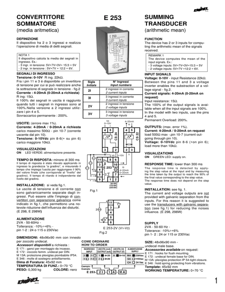
Fra i pin 11 e 3 è disponibile un invertitore
di tensione per cui si può realizzare anche
la sottrazione di segnale in tensione - fig.2
Corrente : 4-20mA (0-20mA a richiesta)
R ing: 15Ω.
Il 100% dei segnali in uscita è raggiunto
quando tutti i segnali in ingresso sono al
100%.Nella versione a 2 ingressi utilizzare i pin 4 e 5.
Sovraccarico permanente : 200%.
INPUT SIGNALS
Voltage: 0-10V - input Resistance 22kΩ.
Between the pins 11 and 3 a voltage
inverter enables the substraction of a voltage signal - fig.2.
Current signals: 4-20mA (0-20mA on
request)
Input resistance: 15Ω.
The 100% of the output signals is available when all the input signals are 100%.
In the model with two inputs, use the pins
4 and 5.
Permanent Overload: 200%.
USCITE: (errore max 1%).
Corrente: 4-20mA / 0-20mA a richiesta
carico massimo 500Ω - pin 10-7 (corrente
uscente dal pin 10).
Tensione: 0-10Vdc pin 8-6(+ su pin 6)
carico maggiore 10kΩ.
Sigla
Initials
2I
3I
2V
3V
N° Ingressi
Input numbers
2 ingressi in corrente
2 current inputs
3 ingressi in corrente
3 current inputs
2 ingressi in tensione
2 voltage inputs
3 ingressi in tensione
3 voltage inputs
OUTPUTS: (max. error 1%).
Current: 4-20mA / 0-20mA on request
load 500Ω max -.pin 10-7 (current outgoing through pin 10).
Voltage: 0-10Vdc pin 8-6 (+on pin 6);
load more than 10kΩ.
VISUALIZZAZIONI
ON
LED VERDE: alimentazione presente.
VISUALIZATIONS
ON
GREEN LED: supply on.
TEMPO DI RISPOSTA: minore di 300 ms
Il tempo di risposta è stato rilevato applicando in
ingresso la grandezza “a gradino”, e misurando il
tempo che impiega l’uscita per raggiungere il 90%
del valore finale (che corrisponde al “livello” del
gradino). Il tempo di ritardo è indipendente dal
livello del gradino.
INSTALLAZIONE: si veda fig.1.
Le uscite di tensione e di corrente non
sono galvanicamente separate dagli ingressi. Può essere utile l’impiego di convertitori con separazione galvanica come
indicato in fig.1, che permettono una notevole riduzione dell’influenza dei disturbi.
(E 298, E 298W)
ALIMENTAZIONE
2VA - 50-60Hz Tolleranza: -10%÷+6% pin 1-2 : 24 o 115 o 230Vac
DIMENSIONI: 48x96x90 mm con innesto
per zoccolo undecal.
Accessori disponibili a richiesta :
E 171 : ganci per montaggio da incasso.
E 172 : zoccolo femm. undecal per DIN.
M 13A: protezione plexiglas piombabile IP54.
E 346 : molle di sostegno antisfilamento.
Dima di Foratura: 45x92 mm
TEMPERATURA DI FUNZ.: 0÷70 °C
PESO: 0,300 kg
COLORE: nero
RESPONSE TIME: lower than 300 ms
The response time is detected by applying the step value at the input and by measuring
the time taken by the output to reach the 90% of
the final value corresponding to the step value.
The response time does not depend on the step
value.
INSTALLATION: see fig. 1.
The current and voltage outputs are not
provided with galvanic separation from the
inputs. For this reason it is suggested to
use the transducers with galvanic separation (see fig.1) for reducing the noises
influence. (E 298, 298W)
SUPPLY
2VA - 50-60 Hz Tolerance: -10%÷+6%
pin 1- 2 : 24 or 115 or 230Vac
SIZE: 48x96x90 mm undecal male base.
Accessories available on request:
E 171 : hooks for flush mounting.
E 172 : undecal female base for DIN.
M 13A: plexiglas protection IP 54-tight closure.
E 346 : hold spring protecting from vibrations.
Template: 45x92 mm
WORKING TEMPERATURE: 0÷70 °C
1

