ITALIANO
INTERFACCIA DI POTENZA
• Alimentazione 230V~
• Possibilità di pilotare quattro Fan Coil a tre velocità
• Attacco per barra Din
Via Prosdocimo, 30
I-36061 BASSANO DEL GRAPPA (VI)
Tel.: +39.0424.567842
Fax.: +39.0424.567849
http://www.seitron.it
e-mail: [email protected]
FAN-COIL POWER INTERFACE
• 230V~ power supply
• Can be wired up to four Fan Coil each with 3-speeds
• Din-rail mount
FAN CONTROL INTERFACE
ENGLISH
GENERALITA’
OVERVIEW
L’interfaccia di potenza per fan-coil è dotato di attacco
per barra-din e quattro uscite per pilotare ciascuna un
motore a tre velocità.
I segnali di comando provenienti da un termostato per
fan coil pilotano ciascuno un relè, il quale a sua volta
comanda la singola velocità del motore ad esso
collegato.
L’interfaccia permette, al termostato cui è collegato, di
pilotare quattro motori di potenza max. 1/10 HP.
This power interface for fan-coils features a DIN-rail
mount capability and four outputs each driving one 3speeds motor.
Each of the signals coming from the 'master' fan-coil
thermostat actually drive one relay, which, in turn,
drives the relevant coil of the fan motor wired to it.
Therefore this interface is capable of driving up to four
motors each having a maximum power of 1/10 HP.
CARATTERISTICHE TECNICHE
TECHNICAL FEATURES
Alimentazione:
230V~ -15% +10% 50Hz
Portata contatti:
4 x 3 (0,3) A @ 250V~ SPDT
Potenza max. mot. monofase: 1/10 HP
Corrente nominale:
3A
Tensione nominale:
250V~
Grado di protezione:
IP 30
Temp. di funzionamento: 0°C .. 40°C
Temp. di stoccaggio:
-10°C .. +50°C.
Limiti di umidita':
10% .. 80% rH
(non condensante)
Contenitore:
Materiale: Tecnopolimero classe V0
Colore:
Grigio chiaro (RAL 7035)
Dimensioni:
105 x 90 x 70 (L X A X P)
Peso:
~ 265 gr.
Power supply:
Contact rating:
Single-phase motor
max power:
Nominal current:
Nominal voltage:
Protection grade:
Operating temperature:
Storage temperature:
Humidity limits:
ATTENZIONE
Material:
Color:
Size:
Weight:
N C 1
2
3
12V
- +
1
2
5
6
7
4
TFE INF
TFE
SCHEDA
DI INF
POTENZA PER 4 FAN- COIL
8
a
2
C
RELE’DIDI
RELE'
19
3 VELOCITA'
3
1
POTENZA
20
2 VELOCITA'
4
2
21
1 VELOCITA'
5
3
POTENZA
3A 250V~
POWER
5A 250V~
RELAY
4
22
23
RELE’DIDI
RELE'
POTENZA
POTENZA
3A 250V~
POWER
5A
250V~
RELAY
RELE'
RELE’DIDI
13
L
14
N
15
L
16
N
POTENZA
POTENZA
3A 250V~
POWER
5A
250V~
RELAY
3
Velocità
Speed
a
a
Velocità
Speed
Nell'ottica di un continuo sviluppo dei propri prodotti, il costruttore si riserva il
diritto di apportare modifiche a dati tecnici e prestazioni senza preavviso.
Il consumatore è garantito contro i difetti di conformità del prodotto per 24
mesi dalla data di vendita secondo la Direttiva Europea 1999/44/CE. Su
richiesta è disponibile presso il venditore il testo completo della garanzia.
3° FAN-COIL
COMUNE
Comune/Common
a
27
3 VELOCITA'
28
2 VELOCITA'
29
1 VELOCITA'
a
a
Velocità
Speed
2° FAN-COIL
COMUNE
Comune/Common
a
31
3 VELOCITA'
32
2 VELOCITA'
a
a
Velocità
Speed
1° FAN-COIL
1 VELOCITA'
COMUNE
Comune/Common
INTERRUTTORI
INTERRUTTORI SINGLE FAN-COIL
SEZIONAMENTO
SEZIONAMENTO
ENABLING
SINGOLI
SINGOLI
SWITCHES
FAN-COIL
FAN-COIL
(OPTIONALS)
(FACOLTATIVI)
(FACOLTATIVI)
L
230V~
N
Fig. 2:
output
WARNING
a
2 VELOCITA'
34
4° FAN-COIL
3 VELOCITA'
1 VELOCITA'
33
for
COMUNE
Comune/Common
25
30
1
a
24
26
2
a
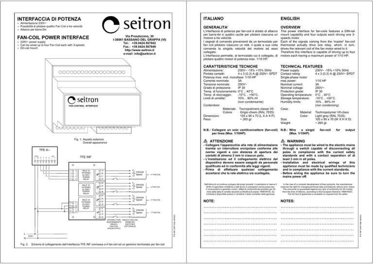
Schema di collegamento dell’interfaccia TFE INF connessa a 4 fan-coil ed un generico termostato per fan-coil
TFE INF 009170A2 060503
3
fan-coil
In the view of a constant development of their products, the manufacturer
reserves the right for changing technical data and features without prior notice.
The consumer is guaranteed against any lack of conformity for 24 months
from the time of delivery, according to the European Directive 1999/44/EC.
The full text of guarantee is available on request from the seller.
NOTE:
NOTES:
………………………………………
………………………………………
………………………………………
………………………………………
………………………………………
………………………………………
………………………………………
………………………………………
………………………………………
………………………………………
………………………………………
………………………………………
………………………………………
………………………………………
TFE INF 009170B2 060503
L
Technopolymer V0-class
Light grey (RAL 7035)
105 x 90 x 70 (W X H X D)
~ 265 gr.
- Collegare l'apparecchio alla rete di alimentazione - The appliance must be wired to the electric mains
through a switch capable of disconnecting all
tramite un interruttore onnipolare conforme alle
norme vigenti e con distanza di apertura dei
poles in compliance with the current safety
contatti di almeno 3 mm in ciascun polo.
standards and with a contact separation of at
- L'installazione ed il collegamento elettrico del
least 3 mm in all poles.
dispositivo devono essere eseguiti da personale - Installation and electrical wirings of this
qualificato ed in conformità alle leggi vigenti.
appliance must be made by qualified technicians
- Prima di effettuare qualsiasi collegamento
and in compliance with the current standards.
- Before wiring the appliance be sure to turn the
accertarsi che la rete elettrica sia scollegata.
mains power off.
TFE A-230V~
1/10 HP
3A
250V~
IP 30
0°C .. 40°C
-10°C .. +50°C.
10% .. 80% rH
(non condensing)
Case:
N.B.: Collegare un solo ventilconvettore (fan-coil) N.B.: Wire
a singol
per linea (Max. 1/10HP).
(Max. 1/10HP)
Fig. 1: Aspetto esteriore
Overall appearance
230V~ -15% +10% 50Hz
4 x 3 (0,3) A @ 250V~ SPDT

