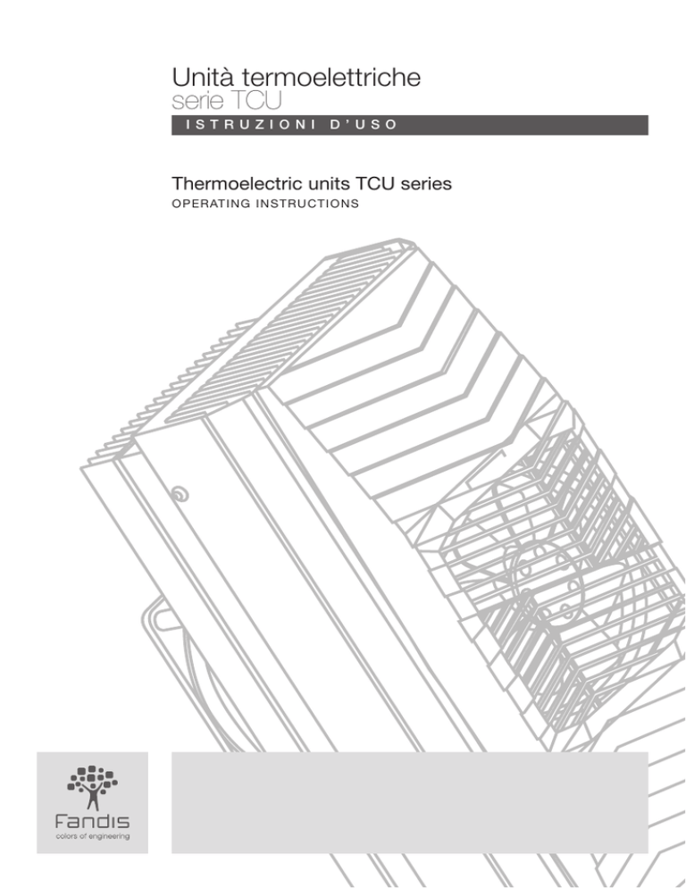
Unità termoelettriche
serie TCU
I s t ru zion I
D ’ USO
Thermoelectric units TCU series
OPERATING INSTRUCTIONS
ENG
Unità termoelettriche
serie TCU
I s t r u z io nI
ITA
Thermoelectric units
TCU series
D ’ USO
OPERATING
FUNZIONAMENTO
1 Tensione e corrente
2 Alimentazione
3 Potenza frigorifera
3
ENG
FUNZIONAMENTO
Unità termoelettriche serie TCU
Thermoelectric units TCU series
I NSTRU C T I ONS
OPERATION
1 Input voltage and current
2 Power supply
3 Cooling power
3
4
CONNESSIONE ELETTRICA
4
ELECTRICAL CONNECTION
MONTAGGIO
5
MOUNTING
5
FLUSSI D’ARIA
6
AIR FLOW
6
1 Tensione e corrente
1 Input voltage and current
Le unità termoelettriche (TE) funzionano in corrente
continua. Sull’etichetta dell’unità TE sono riportati
i seguenti valori elettrici (vedi Fig. 1):
• tensione di alimentazione nominale (Vd.c.);
• corrente nominale e corrente massima nominale (A).
Il valore nominale di corrente assorbita si riferisce alla
situazione di regime. Il valore di corrente massima
nominale è il valore della corrente di spunto negli istanti
successivi all’accensione da freddo dell’unità TE, quando
è alimentata alla tensione nominale;
• potenza frigorifera (W). Questa voce non deve essere
confusa con la potenza elettrica assorbita, che a regime
è data dal prodotto di corrente e tensione nominali.
Il rapporto tra potenza frigorifera e potenza elettrica
assorbita è il COP (coefficient of performance) dell’unità TE;
• l’unità può funzionare anche a tensioni diverse
da quella nominale: l’intervallo di funzionamento
è indicato sul data sheet.
La corrente assorbita è direttamente proporzionale
alla tensione di alimentazione, perciò se quest’ultima è
superiore al valore nominale, lo sarà anche la corrente.
The thermoelectric units (TE) operate with direct current.
On the TE unit label are indicated the following electric
values (Fig. 1):
• rated voltage (Vd.c.);
• rated current and maximum rated current (A).
The rated value of input current is referred to the steady
state situation. The maximum rated current value is the
value of the start-up current when the TE unit is powered
by rated voltage;
• cooling power (W). This entry must not be mistaken
with the electrical input power which is given by the
multiplication between rated current and voltage,
in the steady state. The ratio between cooling power
and electrical input power is the COP (coefficient of
performance) of the TE unit;
• the TE unit can work even when powered at different
voltages from the rated one: the voltage range is shown
on the data sheet.
Input current is proportional to the input voltage:
so if the actual input voltage is greater than the rated
one, also the actual input current will be greater than the
rated one.
2 Alimentatore
LATO CALDO - WARM SIDE
OPERATION
LATO FREDDO - COLD SIDE
Per un corretto funzionamento dell’unità TE è necessario
che l’alimentatore sia dimensionato in base al valore della
corrente massima nominale (A max).
Assicurarsi che l’alimentatore abbia un’ondulazione
massima di corrente inferiore al 5%.
3 Potenza frigorifera
Quando l’unità TE viene alimentata alla tensione
nominale, essa fornisce la potenza frigorifera nominale.
La potenza frigorifera nominale, riferita ad una
temperatura ambiente di 25°C e a un salto termico ΔT
(temperatura ambiente - temperatura interna) = 0,
è indicata sull’etichetta dell’unità TE alla voce W.
La potenza frigorifera (Qc ) e ΔT sono tra loro
inversamente proporzionali. Un esempio di andamento
della potenza frigorifera nominale in funzione del salto
termico ΔT è visualizzata in Fig. 2.
La potenza frigorifera è direttamente proporzionale
alla tensione di alimentazione, perciò se quest’ultima
è inferiore al valore nominale, lo sarà anche la potenza
frigorifera.
Fig. 1
2 Power supply
In order to have a correct working of the TE unit, the
power supply must be selected considering the max
rated current value (A max).
The maximum ripple of the power supply must not be
greater than 5%.
3 Cooling power
When the TE unit is powered at the rated voltage, it
supplies the rated cooling power.
The rated cooling power, referred to the ambient
temperature of 25°C and the thermal gradient ΔT
(ambient temperature - enclosure temperature) = 0,
is shown on the TE unit label under the entry W.
The cooling power (Qc ) and ΔT are inversely proportional.
An example of the dependency of the rated cooling
power from ΔT is shown in Fig. 2.
The cooling power is proportional to the input voltage,
so if the actual input voltage is smaller than the rated
value, also the actual cooling power will be smaller than
the rated one.
Fig. 2
120
100
Qc (W)
Cooling Power
ITA
80
60
40
20
0
I dati ed i disegni contenuti in queste istruzioni d’uso
si riferiscono a titolo di esempio e potrebbero non corrispondere
a quelli dell’unità TE presente nella confezione.
The data and drawings contained in this operating instructions
are just an example and they could be different from those
of the TE unit present in the packaging.
0
5
10
15
20
25
30
35
40
∆T (°C)
T ambient - T enclosure
3
ITA
ENG
CONNESSIONE ELETTRICA
ITA
ELECTRICAL CONNECTION
Unità termoelettriche serie TCU
Thermoelectric units TCU series
Per connettere l’unità termoelettrica all’alimentatore,
seguire lo schema di Fig. 3 e Fig. 4.
Per il cablaggio dei moduli termoelettrici, utilizzare dei
conduttori di sezione 1mm2 o AWG 18, mentre per il
cablaggio dei ventilatori sono sufficienti dei conduttori di
sezione 0,5mm2 o AWG 20.
La Fig. 5 mostra come connettere i cavi di alimentazione.
A cablaggio ultimato, per disconnettere l’unità
dall’alimentatore, separare il connettore maschio da
quello femmina come mostrato in Fig. 6.
Fig. 3
To connect the thermoelectric unit to the power supply
follow the scheme in Fig. 3 and Fig. 4.
To connect the TE modules use 1mm2 or AWG 18
conductors. To connect the fans use 0.5mm2 or AWG 20
conductors.
Fig. 5 shows how to connect the wires from the power
supply. After the wiring, to disconnect the TE unit from
the power supply, separate the male connector from the
female one, as shown in Fig. 6.
Fig. 4
+V
-V
GND
N
L
POWER
SUPPLY
Fig. 5
TCU
UNIT
POWER
SUPPLY
+V
-V
GND
N 1
L 2
ENG
MONTAGGIO
MOUNTING
Unità termoelettriche serie TCU
Thermoelectric units TCU series
The TE unit is mounted on the cabinet wall by means of
its mounting cut-out (see Fig. 7 e 8), using M5 screws.
The screw length must be equal to10 mm + cabinet wall
thickness.
The greater TE unit heat sink, which is enclosed in a RAL
7032 coloured covering and has the M5 holes used to fix
the unit on the wall, must be external to the cabinet.
We recommend to keep the cabinet, on which the TE
unit will be mounted, quite hermetic in order to avoid a
continuous formation of condensate.
If an enclosure temperature lower than the ambient
temperature is wanted, it is necessary to cover the
cabinet walls with insulating panels in order to reduce
the thermal dissipation of the cabinet surface.
L’unità TE viene installata a parete tramite la sua dima di
foratura (vedi Fig. 7 e 8), utilizzando per il fissaggio viti
M5 di opportuna lunghezza (10mm + spessore parete).
Il dissipatore più grande dell’unità TE, che è racchiuso
in una copertura di colore RAL 7032 e nel quale sono
presenti i fori M5 di fissaggio dell’unità alla parete, deve
rimanere all’esterno del contenitore da raffreddare.
Si consiglia di rendere sufficientemente ermetico il
contenitore su cui sarà montata l’unità TE, per evitare
una formazione continua di condensa al suo interno.
Se la temperatura all’interno del contenitore deve essere
inferiore a quella ambiente, è necessario rivestirne
le pareti con pannelli isolanti in modo da diminuire la
dispersione termica della superficie del contenitore.
Fig. 8
+ V moduli TE
+ V TE modules
+ V ventilatori
+ V fans
3
- V moduli TE
- V TE modules
4
- V ventilatori
- V fans
TCU
UNIT
spelare 8 mm
strip 8 mm
Fig. 7
1
premere con un cacciavite
push using a screwdriver
Fig. 6
­
±
±
­
°
2
inserire il conduttore
insert the conductor
­
±
4
5
ITA
ENG
FLUSSI D’ARIA
ITA
AIR FLOWS
Unità termoelettriche serie TCU
Thermoelectric units TCU series
Assicurarsi che i flussi d’aria all’uscita dei dissipatori
o all’ingresso dei ventilatori non vengano ostacolati
da oggetti circostanti. Per un corretto funzionamento
dell’unità TE si consiglia di lasciare libera l’area intorno
all’unità come indicato in Fig. 9.
Se la parete sulla quale viene montata l’unità ha uno
spessore maggiore dell’isolante dell’unità TE, si consiglia
di tagliare la parete con un angolo minore o uguale
a 45° come indicato in Fig. 10. In questo modo non
si ostacolano i flussi d’aria in uscita dal dissipatore,
aumentando le prestazioni dell’unità TE rispetto al caso
in cui le pareti siano diritte (vedi Fig. 11).
Be sure that the air flows outgoing from the heat sinks
and incoming to the fans are not obstructed by the
nearing objects. For a correct working of the TE unit we
recommend to keep clear the area around the unit as
shown in Fig. 9.
If the cabinet wall, on which the unit is mounted, is
thicker than the TE unit insulation, we recommend to cut
the wall with an angle less-then or equal to 45° degree
as shown in Fig. 10. In this way the air flow outgoing
from the heat sink is not obstructed and the TE unit has
a better performance than in the case of sharp edge
cut-out (see Fig. 11).
Fig. 9
RESPONSABILITÀ TECNICHE
TECHNICAL RESPONSIBILITIES
Le connessioni elettriche devono essere eseguite
in accordo con le norme di sicurezza vigenti.
Nel caso i prodotti debbano garantire un funzionamento
continuo, è necessario installare almeno un dispositivo
di allarme che segnali eventuali interruzioni
o malfunzionamenti del prodotto.
Direttive e norme devono essere rispettate.
Electrical connections must be carried out according
to recognised safety rules.
In case the products have to guarantee a continuous
operation, it is necessary to install at least an alarm
device signalling the product’s interruption or failure.
Directives and norms must be observed.
AVVERTENZE
Disconnect the mains supply before carrying out any
operation on the product.
-the electrical connection must be carried out according
to the local norms and safety regulations which govern
the use of electrical material;
-electrical connection must be carried out by qualified
personnel only;
- the voltage must be according to the rated values
stated on the name plate.
In determinate condizioni ambientali si può formare
della condensa sul dissipatore freddo dell’unità TE.
La condensa può entrare in contatto con parti in tensione
di apparecchiature secondarie prossime all’unità TE,
con possibile danno all’operatore, alle apparecchiature
secondarie e all’unità TE stessa. Se tale pericolo esiste,
devono essere utilizzati dei dispositivi per prevenire la
condensa o per raccoglierla e rimuoverla in modo sicuro.
In Fig. 12 è rappresentato un tipico esempio di
installazione dell’unità TE montata a parete, con le alette
del dissipatore posizionate verticalmente, in modo da
guidare la condensa verso il basso dove può essere
raccolta mediante un’apposita vaschetta* e convogliata
all’esterno mediante un tubo* di gomma.
In some ambient conditions we can find the presence
of condensate on the cooling dissipator of TE unit.
The condensate can get in touch with live parts
of minor equipment next to the TE unit and cause
damages to workers, minor equipment and also to the
TE unit.
If there is this risk, some devices must be used in order
to prevent condensate or collect and remove it safely.
In Fig. 12 is represented an example of typical mounting
of the TE unit on the wall, with the heat sink fins vertically
positioned.
In this way the condensate is guided downward where it
could be gathered in a small basin* and carrird outside
by a drainage pipe*.
GARANZIA
WARRANTY
La garanzia è prestata secondo quanto previsto dalle
“Condizioni generali di vendita”.
For warranty conditions see “General Sales
Conditions”.
*prodotto non compreso nella confezione
*product not included in the packaging
Fig. 12
Fig. 10
Fig. 11
α ≤ °
α ≤ °
α ≤ °
6
ADVICE
Disinserire la tensione prima di eseguire qualsiasi
operazione sul prodotto.
- eseguire l’allacciamento elettrico nel rispetto
delle norme vigenti e delle prescrizioni locali a tutela
della sicurezza nell’impiego di materiale elettrico;
- l’allacciamento elettrico deve essere eseguito
da personale qualificato;
- la tensione di alimentazione deve corrispondere
ai valori nominali riportati sulla targhetta.
ENG
TIU-A01/1_ie_pomcal_0412_LTP
Fandis S.p.A.
Via per Castelletto 65/69, 28040 Borgo Ticino (NO) - Italy
Tel. +39 0321 96 32 32 - Fax +39 0321 96 32 96 - [email protected] - www.fandis.it

