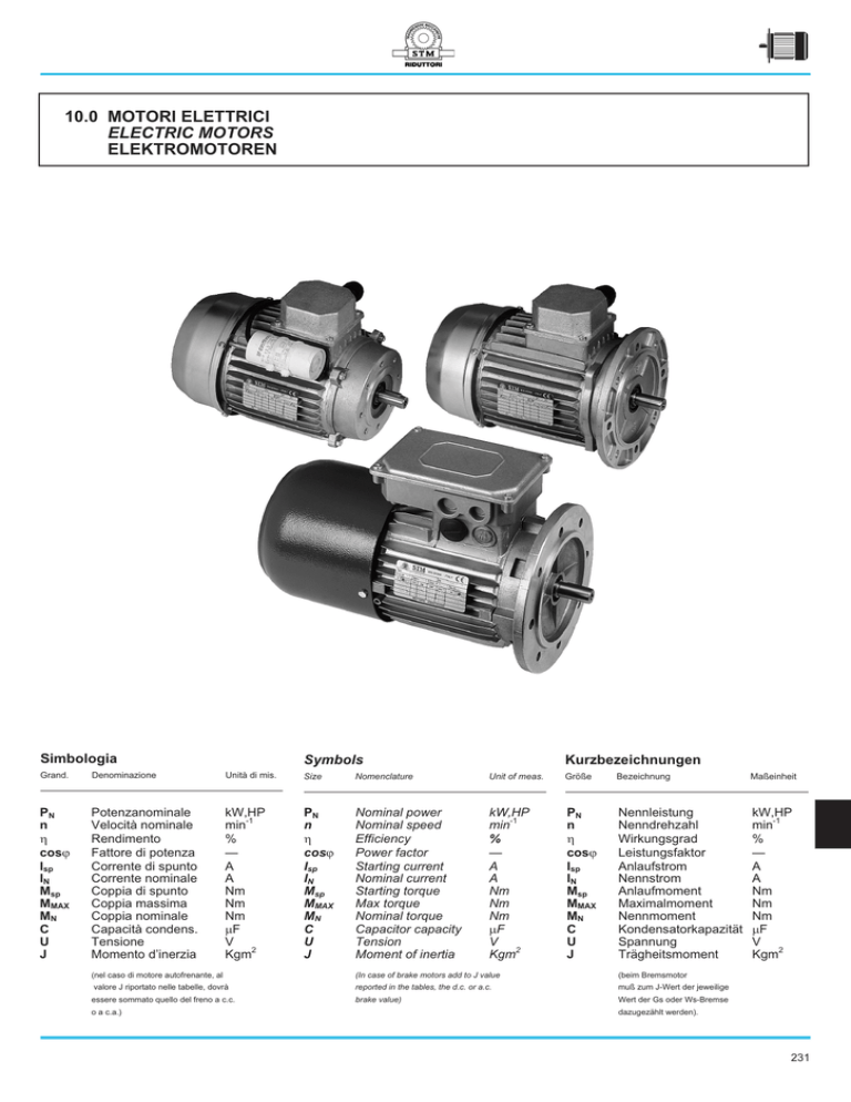
10.0 MOTORI ELETTRICI
ELECTRIC MOTORS
ELEKTROMOTOREN
Simbologia
Symbols
Kurzbezeichnungen
Grand.
Denominazione
Unità di mis.
Size
Nomenclature
Unit of meas.
Größe
Bezeichnung
Maßeinheit
PN
n
h
cosj
Isp
IN
Msp
MMAX
MN
C
U
J
Potenzanominale
Velocità nominale
Rendimento
Fattore di potenza
Corrente di spunto
Corrente nominale
Coppia di spunto
Coppia massima
Coppia nominale
Capacità condens.
Tensione
Momento d’inerzia
kW,HP
min-1
%
—
A
A
Nm
Nm
Nm
mF
V
Kgm2
PN
n
h
cosj
Isp
IN
Msp
MMAX
MN
C
U
J
Nominal power
Nominal speed
Efficiency
Power factor
Starting current
Nominal current
Starting torque
Max torque
Nominal torque
Capacitor capacity
Tension
Moment of inertia
kW,HP
min-1
%
—
A
A
Nm
Nm
Nm
mF
V
Kgm2
PN
n
h
cosj
Isp
IN
Msp
MMAX
MN
C
U
J
Nennleistung
Nenndrehzahl
Wirkungsgrad
Leistungsfaktor
Anlaufstrom
Nennstrom
Anlaufmoment
Maximalmoment
Nennmoment
Kondensatorkapazität
Spannung
Trägheitsmoment
kW,HP
min-1
%
—
A
A
Nm
Nm
Nm
mF
V
Kgm2
(nel caso di motore autofrenante, al
(In case of brake motors add to J value
(beim Bremsmotor
valore J riportato nelle tabelle, dovrà
reported in the tables, the d.c. or a.c.
muß zum J-Wert der jeweilige
essere sommato quello del freno a c.c.
brake value)
Wert der Gs oder Ws-Bremse
o a c.a.)
dazugezählt werden).
231
10.1 Caratteristiche generali
10.1 General characteristics
10.1 Allgemeine Merkmale
Tipi e versioni
Types and versions
Typen und Versionen
I motori a corrente alternata sono previsti
nelle seguenti versioni:
A.c. motors are supplied in the following
versions:
Die Wechselstrommotoren gibt es in
folgenden Versionen:
TN
Trifase standard / Standard Threephase Motor / Standard - Drehstrommotor
DN
Trifase, polarità doppia / Threephase, double speed / Polumschaltbare Drehstrommotor
MN
Monofase standard / Standard Single phase motor / Standard - Einphasenmotor
XN
Monofase con alta coppia di spunto / Single phase motor with high starting torque / Einphasenmotor mit
hohem Anlaufmoment
TF
Trifase autofrenante standard / Standard Threephase brake motor / Standard - Drehstrom - Bremsmotor
DF
Trifase autofrenante, polarità doppia / Threephase brake motor, double speed / Polumschaltbarer Drehstrom Bremsmotor
MF
Monofase autofrenante standard / Standard single phase brake motor / Einphasen - Bremsmotor
XF
Monofase autofrenante con alta coppia di spunto / Single phase brake motor with high starting torque / Einphasen Bremsmotor mit hohem Anlaufmoment
L’intera gamma attuale di motori, dalla
grandezza 56 alla 132, utilizza carcasse e
coperchi in alluminio pressofuso, ventole
esterne bidirezionali costruite in materiale
plastico e calotte copriventola in lamiera
d’acciaio.
Tutte le caratteristiche dimensionali e
costruttive dei motori STM sono conformi
alle norme IEC, UNEL, CEI.
In the whole range, from size 56 to 132,
housings and covers are made of die-cast
aluminium, the external bidirectional fans
are made of plastic material and the fan
covers in steel sheets.
The
dimensional
and
constructive
characteristics of STM motors conform to
IEC,UNEL,CEI specifications.
Alle Modelle der derzeitigen Motorenpalette,
von Baugrösse 56 bis 132, haben Gehäuse
und Deckel aus Aluminium-Druckguß, die
externen, bidirektionalen Ventilatoren Kunststoff und die Lüfterhauben aus Stahlblech.
Maße und Konstruktionsmerkmale der STMMotoren entsprechen den Anforderungen
der IEC, UNEL und CEI-Normen.
10.2 Designazione
10.2 Designation
10.2 Bezeichnung
Tipo
Type
Typ
Grand.
Size
Größe
Potenza
Power
Leistung
N. poli
N. poles
Polzahl
TN
63
0.18
4
TN
DN
MN
XN
TF
DF
MF
XF
56
....
200
Kw
(HP)
2
4
6
8
2/4
4/6
4/8
Tensione Frequenza Protezione Isolamento Forma costruttiva
Voltage Frequency Protection Insulation Mounting positions
Spannung Frequenz Schutzart
Isolation
Bauform
230/400
50
IP55
CL F
B5
230-400V
50 Hz
standard
IP55
CL F
B5
B14
B3 pos.1
standard
standard
standard
trifase
threephase
standard
60 Hz
Drehstrom a richiesta
CL H
IP44
B3L pos.2
a richiesta
IP54
on request
B3L pos. 3
230V
IP65
on request
auf Anfrage
B3/B5
standard
a richiesta auf Anfrage
B3/B14
monofase
on request
a rich. /on req./auf
singlephaseEi
auf Anfrage
Anfrage
nphasen
FLANGE RIDOTTE E MAGGIORATE DISPONIBILI
SPECIAL FLANGES AVAILABLE
LIEFERBARE SONDERFLANSCHE
Tipo motore
Motor type
Motortyp
63
71
80
90
100
112
132
232
B14 ridotta
Reduced
Reduziert
Tipo flangia / Flange type / Flanschtyp
B14 maggiorata
Oversize
Übermaß
B5 ridotta
Reduced
Reduziert
56 B14
63 B14
71 B14
80 B14
90 B14
90 B14
—
71 - 80 B14
80 - 90 B14
90 - 100 B14
100 B14
132 B14
—
—
—
63 B5
71 B5
71 B5
90 B5
90 B5
112 B5
ALTRE SPECIFICHE
OTHER SPECIFICATIONS
WEITERE SPEZIFIKATIONEN
tutti/all/alle
Albero bisporgente
Double extended output shaft
Beidseitig Abtriebswelle
XN
XF
Condensatore di avviamento
Starting Capacitor
Anlaufkondensator
TF
DF
Freno c.a. (standard per trifase)
A.C. brake (standard on threephase)
Ws-Bremse (Standard für Drehstrommotor)
TF
MF
DF
Freno c.c. (standard per monofase)
D.C. brake (standard on single phase)
Gs-Bremse (Standard für Einphasenmotor)
TF
MF
DF
Scheda frenatura rapida (per freno c.c.)
Fast braking card (on D.C. brake)
Schnellbrems-Karte (für Gs-Bremse)
TF
MF
DF
Leva di sblocco
Hand release
Manuelle Entsperrung
Tropicalizzazione
Tropicalization
Tropenschutz
tutti/all/alle
Albero ridotto
Reduced shaft
Kleinwelle
Flangia ridotta
Special Flanges
Sonderflansche
L
10.3 Caratteristiche meccaniche
10.3 Mechanical characteristics
10.3 Mechanische Merkmale
Forma costruttiva
Construction form
Bauform
Tutti i motori sono previsti nelle seguenti forme
costruttive:
Fig. 10.1
Standard all motors are supplied in the following
types:
Standard alle Motoren sind in folgenden Bauformen
erhältlich:
Protezioni
Protection
Schutzarten
La protezione standard è la IP55; a richiesta
i motori possono essere forniti con un grado
di protezione IP54 e IP65.
Standard protection supplied is IP55.
IP54 and IP65 protections are also
available upon request.
Die Standard Schutzart ist IP55. Auf
Anfrage sind die Motoren jedoch auch IP54
und IP65 lieferbar.
Scatola morsettiera
Terminal box
Klemmenkasten
Nelle forme costruttive con piede la scatola
morsettiera può essere orientata in tre
posizioni. Essa è posta normalmente in alto
(1); a richiesta può essere collocata a
destra (3) o, tramite esecuzione speciale, a
sinistra (2).
Nei motori a polarità singola o doppia
contiene 6 morsetti (a richiesta 12).
In the foot mounted types, the terminal box
can be located in three different positions.
On the standard type it is located on the top
(1), upon request it can be located on the
right (3) or on the left hand side (2).
Standard and double speed motors are
equipped with a six terminals board (12
upon request).
In der Bauform mit Fuß gibt es für den
Klemmenkasten drei Montagemöglichkeiten.
Normalerweise befindet er sich oben (1). Er
kann aber auf Anfrage auch rechts (3) oder in
Sonderausführung links (2) plaziert werden.
Bei ein-oder doppelpoligen Motoren enthält
das Klemmbrett 6 Klemmen (auf Anfrage
12).
2
1
3
Esecuzione speciale
Special execution
Sonderausführung
Standard
A richiesta
On request
Auf Anfrage
Carichi radiali
Radial loads
Radialbelastungen
La tabella sottostante riporta i massimi carichi
radiali (N) ammissibili sulla mezzeria della
sporgenza dell’albero. motore .
The table underneath lists the maximum
radial loads (N) allowable on the centerline
of the shaft extension.
In der nachstehenden Tabelle sind die
maximal zulässigen Radialbelastungen (N)
auf die Mitte des Abtriebswelle angegeben.
min-1
3000
1500
1000
750
56
240
300
350
—
63
270
350
400
400
Grandezza motore / Motor size / Motorbaugröße
71
80
90
100
330
430
490
670
410
540
610
850
470
610
700
970
470
610
770
1070
112
960
1210
1390
1390
132
1370
1730
1980
1980
233
10.4 Caratteristiche elettriche
motori trifase
10.4
Electrical characteristics
threephase motors
10.4 Elektrische Merkmale
Drehstrommotoren
Potenza
Power
Leistung
I valori di potenza riportati nelle tabelle di
selezione sono calcolati per servizio continuo (S1)con temperatura ambiente max di
40 °C, altitudine inferiore a 1000 msl, alimentazione a tensione nominale, frequenza a 50Hz e valgono anche nel caso in
cui la tensione nominale subisca delle
variazioni contenute fra +5% e - 5%.
Per condizioni operative e ambientali diverse, interpellare il ns. Servizio Clienti.
Motor ratings listed in our selection tables
are calculated for continuous duty (S1) in
an ambient temperature of max 40°C,
altitude below 1000 mt asl, normal voltage
and 50Hz frequency.These values remain
constant also in case of tension variations
between + 5% and - 5%.
For operating conditions different from the
above, it is advisable to contact our
Customer Service.
Die in den Tabellen angegebenen Leistungen sind für Dauerbetrieb (S1), Umgebungstemperaturen von max. 40°C, Höhenlage
unter 1000 m ü.M., Nennstromversorgung
und Frequenz von 50 Hz berechnet. Sie
gelten auch bei Nennspannung mit kleinen
Schwankungen zwischen +5% und -5%.
Bei anderen Arbeitsoder Umgebungsbedingungen wenden Sie sich bitte an
unseren Kundendienst.
Tensione e frequenza
Frequency and tension
Spannung und Frequenz
I valori di tabella sono relativi a tensione
nominale 230 - 400 V e 50 Hz.
E’ ammessa tolleranza di tensione ± 5%.
Se un motore normale viene impiegato a 60
Hz, indicativamente occorre considerare le
seguenti variazioni:
Values given in the table are relevant to
nominal tension 230 - 400 V and 50 Hz.
It is allowable a tension tolerance of ± 5%.
Should a standard motor be used at 60Hz,
the following variations have to be
considered:
Die Tabellenwerte beziehen sich auf eine
Nennspannung von 230 - 400 V und 50 Hz
Spannungstoleranzen von ± 5% sind
zulässig. Wird ein normaler Motor bei 60 Hz
betrieben, müssen folgende Abweichungen berücksichtigt werden:
PN
C°
cosj
MN
MMAX/MN
Msp/MN
n
=
=
=
– 17%
– 15%
– 30%
+ 20%
Classe di isolamento
Insulation class
Isolationsklasse
Gli avvolgimenti, realizzati con filo a doppio
smalto al massimo della tolleranza e
sottoposti ad impregnazione sotto vuoto,
sono isolati in classe F garantendo in tal
modo un margine termico massimo di 155
°C, conforme alle prescrizioni delle principali normative. Per particolari applicazioni
è possibile fornire (a richiesta) l’isolamento
in classe H e motori sottoposti a trattamenti
speciali per renderli atti a funzionare in
ambienti umidi e corrosivi.
Windings are made of copper wire with
double thickness enamelling and are
subjected to vacuum impregnation.
They are also class F insulated granting a
maximum thermal margin of 155 °C
according to the main specifications.
For particular applications it is possible to
supply (upon request)class H insulated
motors.
Specially treated motors suitable to operate
in humid and corrosive ambients are also
available upon request.
Die Wicklungen sind mit einer doppelten
Lackschieht versehen und vakuumimprägniert. Sie sind nach Klasse F isoliert und
garantieren somit einen den einschlägigen
Normen entsprechenden maximalen Temperaturgrenzwert von 155°C.
Für besondere Anforderungen können die
Motoren auf Anfrage mit einer Isolierung
nach Klasse H und speziellen Schutzbehandlungen für feuchte und korrosive
Arbeitsumgebungen geliefert werden.
Schemi di collegamento motori
trifase
Threephase motor wiring diagram
Schaltungsplan für Drehstrommotoren
Fig. 10.2
Motori a due velocità
Two speed motors
Polumschaltbare Motoren
234
10.5 Caratteristiche elettriche
motori monofase
10.5
Electrical characteristics
single phase motors
10.5 Elektrische Merkmale
Einphasenmotoren
Generalità
General
Allgemeines
I motori monofase STM sono dotati di un
condensatore di marcia sempre inserito e
collegato in serie all’avvolgimento sussidiario di avviamento.
I dati tecnici riportati nelle tabelle sono riferiti a condizioni di esercizio continuo a corrente alternata 230 V - 50 Hz.
Le dimensioni sono identiche a quelle dei
motori trifase, fatta eccezione per l’ingombro del condensatore.
Il condensatore viene montato su apposito
supporto che permette di isolarlo dal corpo
motore limitando la trasmissione di temperatura e vibrazioni al condensatore stesso.
STM single phase motors are equipped
with a run capacitor permanently turned on
and connected to the auxiliary winding for
starting.
Technical data reported in the tables are
referred to continuous duty conditions at
alternating current 230V - 50 Hz.
Overall dimensions are identical to the
threephase motors, except for the capacitor.
The capacitors is assembled on to an
appropriate support that enables to isolate
it from the housing limiting the trasmission
of temperature and vibrations to the
capacitor itself.
Die STM-Einphasenmotoren sind mit
einem ständig aktivierten, in Serie zur HilfsAnlaufwicklung geschalteten Kondensator ausgestattet.
Die technischen Daten in der Tabelle beziehen sich auf Dauerbetrieb mit WsVersorgung von 220 V - 50 Hz.
Die Abmessungen stimmen, mit Ausnahme
der Außenmasse der Kondensatoren,
genau mit denen der Drehstrommotoren
überein.
Der Kondensator ist auf ein Speziallager
montiert, das ihn vom Motorkörper und somit
von Wärme-und Schwingungsübertragungen isoliert.
Alta coppia di spunto (XN-XF)
High starting torque (XN-XF)
Hohes Anlaufmoment (XN-XF)
Nelle applicazioni dove è richiesta una
coppia di spunto elevata, i motori monofase
potranno essere dotati ( a richiesta) di un
condensatore ausiliario, inserito solo nella
fase di avviamento, che permette una
coppia di spunto del 200%. Ad avviamento
avvenuto, il condensatore ausiliario viene
disinserito tramite un relé elettronico.
In those applications where a high starting
torque is required, single phase motors can
be equipped (upon request) with an
auxiliary capacitor which is connected only
in the starting phase and allows a starting
torque of 200%. Once the motor has been
started, the auxiliary capacitor is disconnected by means of an electronic relay.
Bei Anwendungen, wo eine hohes
Anlaufmoment erforderlich ist, können die
Einphasenmotoren auf Anfrage mit einem
nur in der Anlaßphase aktivierten Hilfskondensator ausgerüstet werden, der ein
200%- iges Anlaufmoment ermöglicht.
Nach dem Start wird dieser Hilfskondensator mit einem elektronischen Relais
abgeschaltet.
Classe di isolamento e protezione
Insulation class and protection
Isolationsklasse und Schutzart
Come i motori trifase, anche i monofase
sono realizzati con isolamento corrispondente alla classe F e protezione IP 55.
Single phase motors are supplied with
insulation class F and IP55 protection as
well as the threephase ones.
Auch die Einphasenmotoren sind wie die
Drehstrommotoren in der Isolationsklasse
F und in der Schutzart IP55 hergestellt.
Senso di rotazione
Direction of rotation
Drehrichtung
I motori vengono forniti con senso di rotazione antiorario guardando l’albero.
Gli schemi sotto riportati indicano i collegamenti da effettuare per ottenere un determinato senso di rotazione dell’albero del
motore monofase (osservato di fronte).
Motors are supplied with anticlockwise
rotation looking at the shaft. The diagrams
underneath indicate the connections to be
effected in order to obtain a determinated
direction of the rotation on the single phase
motor shaft (seen from the front).
Die Drehrichtung der Motoren ist, von der
Welle aus betrachtet, gegen den Uhrzeigersinn. Die nachstehenden Anschlußpläne
gelten für bestimmte Drehrichtungen der
Welle des Einphasenmotors (von vorne
betrachtet).
Avvolgimento simmetrico
Symmetrical winding
Symmetrische Wicklung
A richiesta, i motori elettrici monofase possono essere forniti con un avvolgimento
simmetrico per consentire il funzionamento
in entrambi i sensi di marcia senza necessità di arresto del motore.
Lo schema sottoriportato indica il collegamento necessario per ottenere il senso di
rotazione desiderato.
Upon request single phase electric motors
can be supplied with a symmetrical winding
in order to allow them to operate in both
directions of rotation without stopping the
motor.
The diagram indicates the connection
necessary to obtain the required direction
of rotation.
Auf Anfrage können die Einphasen- Elektromotoren mit einer symmetrischen Wikklung für den Betrieb in beide Laufrichtungen,
ohne Anhalten des Motors, ausgerüstet
werden.
Nachstehend das Anschlußschema für die
gewünschte Drehrichtung.
Schemi di collegamento
motori monofase
Single phase motor wiring diagram
Schaltplan für Einphasenmotoren
Fig. 10.3
Monofase, avvolgimento equilibrato
Single phase, balanced winding
Einphasig, symmetrische Wicklung
235
10.6 Motori autofrenanti
10.6 Brake motors
10.6 Bremsmotoren
Generalità
General
Allgemeines
I motori autofrenanti nascono dalla applicazione, su un motore a corrente alternata, di
un freno elettromagnetico a disco ad azione
negativa che interviene, quindi, in mancanza di corrente causando l’arresto del motore
e quant’altro da esso comandato.
Il motore autofrenante garantisce quindi
una grande precisione d’arresto in caso di
interruzione volontaria della corrente.
La pressione di frenatura è esercitata con
rapidità da una o più molle al cessare
dell’azione dell’elettromagnete.
Le principali caratteristiche si possono così
riassumere:
Esecuzione possibile su motori trifase e
monofase.
Possibilità di avere l’albero bisporgente.
Possibilità di alimentazione separata del
freno. Questa soluzione è adottata sui
motori a doppia polarità e quando si utilizzi
un inverter.
Frenatura ugualmente efficace nei due sensi
di rotazione senza spostamento assiale
dell’albero.
Semplice regolazione del traferro a freno
montato.
Possibilità di regolazione della coppia frenante.
Brake motors are made with the application
of an electromagnetic disc-brake onto an
a.c. motor which operates in case of lack of
current causing the blocking of the motor
and of the other devices connected to it.
The brake motor grants a high stop
precision in case of voluntary interruption of
current.
Braking pressure is effected in a very fast
way from one or more springs once the
electromagnet stops its action.
The principal characteristics can
be
summed up as follows:
Execution available on threephase and
single phase motors.
Double extended shaft.
Possibility of brake separate feeding. This
solution is advisable on two speed motors
and when an inverter is used.
Braking action effective in both directions of
rotation without axial movement of the
shaft.
Simple adjustment of the air gap once the
brake is assembled.
Possibility of braking torque setting.
Die Bremsmotoren entstehen durch die
Ausrüstung eines Wechselstrommotors
mit einer elektromagnetischen Scheibenbremse, die bei Stromausfall den Motor und
die damit angetriebenen Geräte anhält.
Der Bremsmotor garantiert eine hohe
Stoppgenauigkeit bei gesteuerter Stromunterbrechung.
Der Bremsdruck wird bei Deaktivierung des
Elektromagneten sofort durch eine oder
mehrere Federn erzeugt.
Die Hauptmerkmale sind:
Möglichkeit zur Montage auf alle Drehstromund Einphasenmotoren .
Auf Wunsch mit doppelter Abtriebswelle.
Auf Wunsch mit separater Bremsstromversorgung. Diese Lösung empfiehlt sich bei
Motoren mit doppelter Polung und bei
Benutzung eines Inverters.
Gleiche Bremsleistung in beide Drehrichtungen, ohne Axialverschiebung der Welle
Einfache Luftspaltregelung bei montierter
Bremse.
Regelbares Bremsmoment.
Nel motore autofrenante trifase standard è
prevista l’applicazione di freni alimentati a c.a.;
su richiesta possono essere forniti freni in c.c.
I motori monofase autofrenanti sono sempre
dotati di un freno a c.c.
The standard three-phase brake motor is
supplied with AC brakes, upon request DC
brakes are also available.
The single-phase brake motors are always
equipped with a DC bracke.
Bei den dreiphasigen Drehstrom-Bremsmotoren
in Standardversion ist der Einbau von Ws
-Bremsen vargesehen. Auf Anfrage kann der
Motor auch mit Gs-Bremsen geliefert werden.
Protezione e isolamento
Protection and insulation
Schutzart und Isolation
Il motore autofrenante viene realizzato con
isolamento in classe F e protezione IP54
(IP55 a richiesta).
Brake motors are supplied with insulation
class F and IP54 protection (IP55 on
request).
Der Bremsmotor wird in der Isolationsklasse
F und der Schutzart IP54 gefertigt (IP55 au
anfrage).
Leva di sblocco
Hand release
Entsperrhebel
A richiesta può essere fornita la leva di
sblocco manuale meccanico (fig. 10.4).
Upon request, mechanical hand brake
release can be supplied (fig. 10.4).
Auf Anfrage ist ein Hebel für die manuelle
Entsperrung der Bremse lieferbar (Abb.
10.4).
Fig. 10.4
ANCORA MOBILE
MOVABLE ARMATURE
ANKERSCHEIBE
DISCO FRENO
BRAKE DISK
BREMSSCHEIBE
236
LEVA DI SBLOCCO
HAND RELEASE
ENTSPERRUNGSHEBE
ELETTROMAGNETE
ELECTROMAGNET
ELEKTROMAGNET
10.7 Freno a C.A.
10.7 A.C. Brake
10.7 Ws - Bremse
Caratteristiche tecniche del freno a c.a.
A.C. brake technical characteristics
Technische Merkmale der Ws-Bremse
Motore
Motor
Motor
Mmin*
Nm
Mmax
Nm
IN
T
mm
63
2
5
0.06
6x10⁻⁴
0.2
0.5
71
4
10
0.06
11x10-4
0.2
80
7
20
0.10
16x10-4
90
14
40
0.16
100
26
70
112
35
132
53
J
Kgm2
(400V)
A
Tn
mm
TEMPI DI INTERVENTO FRENO
BRAKE INTERVENTION TIME
BREMSAKTIVIERUNGSZEIT
gmin
mm
Kg
Ta
ms
Tc
ms
1
20
4
1.25
0.5
1
40
4
1.9
0.3
0.6
1
60
6
3
35x10-4
0.3
0.6
1
90
8
5.6
0.22
88x10-4
0.35
0.7
1
120
16
9.7
100
0.65
103x10-4
0.35
0.7
1
140
16
10.3
150
0.90
225xx10-4
0.40
0.8
1
180
16
14.7
* N.B.
La coppia minima indicata è riferita alla configurazione standard con le viti A (par. 10.9 ) completamente
allentate.
Per ottenere dei valori inferiori è necessario
sostituire le molle.
Tutti i motori autofrenanti sono forniti di serie
con la coppia del freno tarata ad un valore
pari al 70% circa della coppia massima.
* NOTE.
The listed minimum torque refers to the standard
configuration with screws A (chapter 10.9)
completely loose.
Springs must be replaced in order to have lower
values.
All brake motors in the standard version are
supplied with a brake torque set to a valued
equal to approx. 70% of the maximum torque.
* HINWEIS.
Das angegebene Mindestdrehmoment bezieht
sich auf die Standard-Konfiguration bei völlig
gelösten Schrauben A (Kapitel 10.9).
Um niedrigere Werte zu erhalten, müssen die
Federn ausgetauscht werden.
Alle Bremsmotoren sind serienmäßig mit einem
Bremsmoment ausgestattet, das auf einen
Wert von ca. 70% des Höchstdrehmomentes
geeicht ist.
Mmin
Mmax
J
T
Tn
Mmin
Mmax
J
T
Tn
Mmin
Mmax
J
T
Tn
= Min. Bremsmoment
= Max. Bremsmoment
= Trägheitsmoment der Buchse
= Min. Luftspaltwert
= Max. Luftspaltwert vor Neueinstellung
gmin
Ta
Tc
IN
= Mindeststärke Bremsbelag
= Öffnungszeit der Bremse
= Schließzeit der Bremse
= Nennstrom der Bremse bei 400V
gmin
Ta
Tc
IN
= Coppia frenante min
= Coppia frenante max
= Momento d’inerzia bussola
= Valore minimo regolazione traferro
= Valore max traferro prima della nuova
regolazione
= Spessore minimo residuo ferodo
= Tempo di apertura freno
= Tempo di chiusura freno
= Corrente assorbita a 400V
Il freno a c.a. è fornito di serie con i seguenti
valori di alimentazione:
= Min braking torque
= Max braking torque
= Moment of inertia of magnet
= Min. value of air gap setting
= Max value of air gap before new setting
adjustement
= Min thickness of brake lining
= Brake opening time
= Brake closing time
= Absorbed current at 400V
gmin
Ta
Tc
IN
A.C. brake is supplied with following
feeding values:
Die Ws-Bremse wird serienmäßig mit
folgenden
Versorgungsspannungen:
Motore
Alimentazione
motore (V)
Alimentazione
freno (V)
Motor
Motor feeding
(V)
Brake feeding
(V)
Motor
Trifase
standard
230/400
230/400
Threephase
standard
230/400
230/400
Drehstrom
standard
230/400
Threephase
double polarity
230/400
Drehstrom
Polumschalt.Mot.
Trifase
doppia polarità
230
400
A richiesta è possibile fornire il freno con
alimentazione separata. Questa soluzione
è consigliata per motori a due velocità o in
caso di alimentazione tramite inverter.
Numero max. di interventi: 20 al minuto.
230
400
Upon request it is possible to supply brakes
with separate feeding. This solution is
advisable on two speed motors or in those
cases where feeding is obtained by means
of an inverter.
Maximum number of starts: 20 per minute.
Motorspannung Bremsspannung
(V)
(V)
230/400
230
400
230/400
230/400
Auf Anfrage ist eine separate Bremsversorgung erhältlich. Diese Lösung empfiehlt sich
bei Polumschaltbaren-Motoren oder bei
invertergesteuerten Motoren.
Maximale Schaltungsanzahl: 20 pro Minute.
237
10.8 Freno a C.C.
10.8 D.C. Brake
10.8 Gs - Bremse
Caratteristiche tecniche del freno a c.c.
D.C. brake technical characteristics
Technische Merkmale der Gs-Bremse
Motore
Motor
Motor
56
63
71
80
90
100
112
132
Mmin*
Nm
Mmax
Nm
J
Kgm2
T
mm
Tn
mm
gmin
mm
1.5
3
1.2x10⁻⁴
0.20
0.35
-4
TEMPI DI INTERVENTO FRENO
BRAKE INTERVENTION TIME
BREMSAKTIVIERUNGSZEIT
Kg
STANDARD
Tc2
ms
Ta1
ms
Ta2
ms
FAST
Tc1
ms
1
—
—
12
30
1.1
2
5
6x10
0.20
0.50
1
100
10
20
30
1.5
4
10
11x10-4
0.20
0.50
1
120
10
25
60
2.2
20
16x10
-4
0.30
0.60
1
150
10
40
100
3.1
-4
7
14
40
35x10
0.30
0.60
1
220
15
50
120
4.9
26
70
88x10-4
0.35
0.70
1
300
30
80
—
8.3
35
100
103x10-4
0.35
0.70
1
200
20
80
—
9.5
150
-4
0.40
0.80
1
200
20
100
—
12.3
53
225x10
* N.B.
La coppia minima indicata è riferita alla configurazione standard con le viti A (par. 10.4) completamente
allentate.
Per ottenere dei valori inferiori è necessario
sostituire le molle.
* NOTE.
The listed minimum torque refers to the standard
configuration with screws A (chapter 10.4)
completely loose.
Springs must be replaced in order to have lower
values.
* HINWEIS.
Das angegebene Mindestdrehmoment bezieht
sich auf die Standard-Konfiguration bei völlig
gelösten Schrauben A (Kapitel 10.4).
Um niedrigere Werte zu erhalten, müssen die
Federn ausgetauscht werden.
Tutti i motori autofrenanti sono forniti di serie
con la coppia del freno tarata ad un valore
pari al 70% circa della coppia massima.
All brake motors in the standard version are
supplied with a brake torque set to a valued
equal to approx. 70% of the maximum torque.
Alle Bremsmotoren sind serienmäßig mit einem
Bremsmoment ausgestattet, das auf einen Wert
von ca. 75% des Höchstdrehmomentes geeicht
ist.
Mmin
Mmax
J
T
Tn
Mmin
Mmax
J
T
Tn
Mmin
Mmax
J
T
Tn
gmin
Ta1
Ta2
Tc1
Tc2
= Coppia frenante min
= Coppia frenante max
= Momento d’inerzia bussola
= Valore minimo regolazione traferro
= Valore max traferro prima della nuova
regolazione
= Spessore minimo residuo ferodo
= Tempo di apertura freno AC
= Tempo di apertura freno DC
= Tempo di chiusura con dispositivo fast.
(a richiesta)
= Tempo di chiusura standard
Il freno a c.c. è fornito di serie con i seguenti
valori di alimentazione:
= Min braking torque
= Max braking torque
= Moment of inertia of magnet
= Min. value of air gap setting
= Max value of air gap before new setting
adjustement
= Min thickness of brake lining
= Brake opening time AC
= Brake opening time DC
= Brake closing time with fast device
(upon request)
= Standard brake closing time
gmin
Ta1
Ta2
Tc1
Tc2
D.C. brake is supplied with following
feeding values:
= Min. Bremsmoment
= Max. Bremsmoment
= Trägheitsmoment der Buchse
= Min. Luftspaltwert
= Max. Luftspaltwert vor
Neueinstellung
= Mindeststärke Bremsbelag
= Öffnungszeit der Bremse AC
= Öffnungszeit der Bremse DC
= Schliesszeit der Bremse mit
Fastvorrichtung
(auf Anfrage)
= Standard-Schließzeit der Bremse
gmin
Ta1
Ta2
Tc1
Tc2
Die Gs-Bremse wird serienmäßig mit folgenden Versorgungsspannungen:
Motore
Alimentazione
motore (V)
Alimentazione
freno (V)
Motor
Motor feeding
(V)
Brake feeding
(V)
Motor
Trifase
standard
230/400
98
Threephase
standard
230/400
98
Drehstrom
standard
230
98
230
98
400
190
400
190
230
98
230
98
Trifase
doppia polarità
Monofase
Threephase
double polarity
Single phase
Drehstrom
Polumschalt. Mot.
Einphasen
Motorspannung Bremsspannung
(V)
(V)
230/400
98
230
98
400
190
230
98
A richiesta è possibile fornire il freno con
alimentazione separata.
Numero max. interventi: 20 al minuto.
Upon request it is possible to supply separate feeded brakes.
Maximum number of starts: 20 per minute.
Auf Anfrage ist eine separate Bremsenversorgung erhältlich.
Maximale Schaltungsanzahl: 20 pro Minute.
N.B. Quando si utilizzano motori autofrenanti a doppia polarità o motori comandati da inverter, si consiglia di adottare
l’alimentazione separata del freno.
NOTE. When two speed brake motors or
motors operated through inverter are used,
it is advisable to adopt brakes with separate
feeding.
HINWEIS.
Bei
Bremsmotoren
(Polumschaltbar
oder
mit
invertersteuerung) empfiehlt sich eine
separate Bremsversorgung.
238
10.8 Freno a C.C.
10.8 D.C. Brake
10.8 Gs - Bremse
Raddrizzatori di corrente
Current rectifiers
Gleichrichter
Tutti i raddrizzatori utilizzati nei nostri motori
sono conformi alla Direttiva Bassa Tensione
(LVD) 73/23/CEE e successive modifiche.
I tipi da noi utilizzati sono i seguenti:
SKB 2/12 per le gr. 56-63-71
NBR 500-1 (colore blu) per le gr. 80 e 90
(fig. 10.5);
SBR 440-1 (colore rosso) per le gr. 100,
112 e 132 (fig. 10.6).
All the current rectifiers used with our motors
comply with the Low Voltage Directives
EEC/73/23 and following changes.
The types we use are the following:
SKB 2/12 for sizes 56-63-71
NBR 500-1 (blue color) for sizes 80 and 90
(fig. 10.5);
SBR 440-1 (red colour) for sizes 100, 112
and 132 ( fig. 10.6).
Alle in unseren Motoren verwendeten
Gleichrichter entsprechen der Richtlinie
bezüglich der Niedrig-Spannung (LVD)
73/23/CEE und deren nachfolgenden
Änderungen.
Wir verwenden die folgenden Typen:
SKB 2/12 für die Baugrößen 56-63-71
NBR 500-1 (Farbe blau) für die Baugrößen
80 und 90 (Abb. 10.5);
SBR 440-1 (Farbe rot) für die Baugrößen
100, 112 und 132 (Abb. 10.6)
Fig. 10.5
Fig. 10.6
Tempi di intervento con raddrizzatori tipo SBR
Time of intervention with rectifiers SBR
Ansprechzeit mit Gleichrichtern vom Typ SBR
Tempi di intervento con raddrizzatori tipo NBR
Time of intervention with rectifiers NBR
Ansprechzeit mit Gleichrichtern vom Typ NBR
Nei motori standard ad una polarità
alimentando il motore si ha la conseguente
alimentazione del raddrizzatore in quanto
esso è collegato alla morsettiera.
Quando si utilizzano motori autofrenanti a
doppia polarità o motori comandati da inverters,
si consiglia di adottare l’alimentazione
separata del freno effettuando i collegamenti
come indicato nelle fig.10.7 e fig. 10.8 per i tipi
NBR 500-1 e SBR 440-1.
Fig. 10.7
In the standard single-pole y motors, the
rectifier is powered through the motor as
the rectifier is connected to the terminal
board.
If two-pole brake motors or motors controlled
by inverters are used, we suggest to power
the brake separately as shown in fig. 10.7
and 10.8 for type NBR 500-1 and SBR 440-1.
Frenata normale / Standard braking / Normaler Bremsvorgang
NBR 500-1
SBR 440-1
Fig. 10.8
Bei den einpoligen Standard-Motoren wird
mit der Motorspeisung gleichzeitig der
Gleichrichter gespeist, da dieser an die
Klemmleiste angeschlossen ist.
Werden zweipolige Bremsmotoren oder durch
Frequenzumrichter gesteuerte Motoren
verwendet, so empfiehlt sich eine separate
Speisung der Bremse. Dabei werden die
Anschlüsse wie in den Abbildungen 10.7
und 10.8 für die Typen NBR 500-1 und SBR
440-1.
Frenata rapida / Fast braking / Schneller Bremsvorgang
NBR 500-1
SBR 440-1
239
10 .9 Verifiche e regolazioni
10.9 Checks and adjustments
10.9 Kontrollen und Einstellungen
Tutti i motori vengono collaudati e la
taratura dei freni viene effettuata ad un
valore pari al 70% circa della coppia
massima in base a una tensione di
alimentazione di 400 Volt.
Nel caso in cui, si avvertano vibrazioni nel
freno é opportuno effettuare i seguenti
controlli e relativi interventi per riportare il
sistema alle normali condizioni operative:
1) Verificare la tensione di alimentazione.
Se essa è inferiore a 400 Volt provvedere a
riportarla al valore nominale oppure
intervenire riducendo la pressione delle
molle agendo come indicato al punto 3).
2) Verifica del traferro.
Con uno spessimetro misurare il traferro T
(distanza fra l’elettromagnete e l’àncora
mobile) controllando che il valore rilevato
rientri nel campo indicato in tabella.
Se questa condizione non fosse verificata,
sarà necessario effettuare la regolazione
allentando i dadi B e agendo sulle viti C fino
a che il traferro non avrà raggiunto il valore
prestabilito.
Ad operazione conclusa stringere nuovamente i dadi B.
Questo controllo e l’ eventuale intervento
dovranno essere effettuati periodicamente
ad intervalli stabiliti in base all’ utilizzo del
freno.
Nel caso in cui sia montata la leva di
sblocco è necessario verificare che un
eccessivo valore del traferro comporti
l’annullamento della coppia frenante
dovuto alla ripresa del gioco della leva
stessa. Nelle tabelle è riportato il valore
max del gioco della leva (X).
3) Regolazione della coppia frenante.
La coppia frenante è proporzionale alla
compressione delle molle E ed è possibile
variarla agendo sulle viti A in successione e
in modo uniforme; a tale proposito si
consiglia di effettuare una rotazione di 1/2
giro a ciascuna vite di regolazione e
riprovare il funzionamento del freno.
Il grafico di fig. 10.9 indica (in valori
percentuali) le coppie frenanti ottenibili in
base ai giri di avvitamento dei grani.
All motors are tested and brakes are set
to a value equal to 70% of the maximum
torque based on a 400 V supply voltage.
Should vibrations be noticed in the brake, it
is advisable to check as indicated below
and carry out the relative operations to
bring the system back to normal working
conditions:
1) Check the supply tension.
Should it be lower than 400 Volts, bring it
back to the nominal value or reduce the
pressure of the springs by regulating as
indicated at point 3).
2) Checking the magnetic gap.
Using a feeler gauge, measure the T
magnetic gap (distance between the
electromagnet and the mobile keeper)
checking that the measured value falls
within the range indicated in the chart.
Should this condition not occur, an
adjustment must be made by unloosening
screw nuts B and by regulating screws C
until the magnetic gap has reached the
preset value.
When this operation is finished, tighten
screw nuts B.
This check and the relative adjustment, if
performed, must be carried out periodically
at intervals set according to how much the
brake is used.
If the release lever has been assembled, it
is necessary to check if the high value of the
magnetic gap has determined the no
intervention of the breaking torque due to
the clearance of the lever itself.
The maximum value of the lever clearance
(X) is shown in the table.
3) Adjusting the braking torque.
The braking torque is proportional to the
compression of springs E and it is possible
to change it by regulating screws A in
sequence and in a uniform manner; on this
matter, it is advisable to rotate each screw
by 1/2 turn and retry the brake functioning.
The fig. 10.9 show the braking torques (in %
values) referred to the number of screw
turns.
Alle Motoren werden zugelassen und
die Eichung der Bremsen wird bei
einem Wert von 70 % des Höchstdrehmomentes bei einer Versorgungsspannung von 400 Volt ausgeführt.
Sollten in der Bremse Vibrationen festgestellt
werden, so sollten die folgenden Kontrollen
und die entsprechenden Instandsetzungsarbeiten durchgeführt werden, um das System
wieder auf die normalen Betriebsbedingungen
zurückzuführen:
1) Die Versorgungsspannung überprüfen.
Sollte diese unter 400 Volt liegen, so sollte
sie auf den Nominalwert zurückgeführt
werden. Andernfalls kann die Spannung
der Federn reduziert werden, indem wie
unter Punkt 3 beschrieben vorgegangen wird.
2) Den Luftspalt überprüfen.
Mit einem Dickenmesser den Luftspalt T
(Distanz zwischen Elektromagnet und
Ankerscheibe) abmessen und dabei überprüfen, ob der festgestellte Wert innerhalb
des in der Tabelle angegebenen Bereiches
liegt.
Sollte dies nicht der Fall sein, muß die
Einstellung neu ausgeführt werden. Dazu
die Schraubenmuttern B lösen und die
Schrauben C drehen, bis der Luftspalt den
vorgeschriebenen Wert erreicht.
Ist dies geschehen, so müssen die Schraubenmuttern B wieder angezogen werden.
Diese Kontrolle und die eventuell erforderliche Neueinstellung sollten regelmäßig
in Intervallen, die den Einsatzzeiten der
Bremse entsprechen, ausgeführt werden.
Sollte eine Handlüftung installiert sein, so
sollte überprüft werden, ob ein übermäßiger
Wert des Luftspaltes nicht zu
einer Annullierung des Bremsmomentes
führt, die auf den Ausgleich des Spiels des
Hebels selbst zurückzuführen ist. In der
Tabelle ist der Höchstwert des zulässigen
Spiels des Hebels (X) aufgeführt.
3) Einstellung des Bremsmoments.
Das Bremsmoment ist proportional zur
Druckspannung der Federn E und es kann
durch aufeinanderfolgendes und gleichmäßiges Einwirken auf die Schrauben
A variiert werden. Diesbezüglich ist es
empfehlenswert, jeweils eine halbe Drehung
auf jeder Einstellungsschraube auszuführen und dann den Betrieb der Bremse
erneut zu überprüfen. Die Grafik in der
Abbildung 10.9 gibt (in Prozentwerten) die
möglichen Bremsmomente je nach den
Verschraubungsumdrehungen der Stifte an.
Fig. 10.9
240
10.9 Verifiche e regolazioni
10.9 Checks and adjustments
10.9 Kontrollen und Einstellungen
Se alimentando il fre no l’elettromagnete non
riesc e a richiamare l’àncora mobile e a
tenerla attratta s enza vibrazioni è necessario
ridurre la pressione delle molle allentando
(in modo uniforme) le viti A. Questa
regolazione dovrà essere effettuata prevedendo una tensione di alimentazione inferiore del 10 - 15% alla nominale.
If, by feeding the brake, the electromagnet
is unable to call back the mobile keeper and
to keep it attracted without any vibrations,
the pressure of the springs must be
reduced by loosening screws A (in a
uniform manner). The adjustment shall be
carried out considering a supply voltage 10
- 15% lower than the voltage rating.
4) Sostituzione elettromagnete.
Nel caso in cui si rendesse necessario
questo intervento, togliere il copriventola e
la ventola, scollegare dalla morsettiera i
cavi di alimentazione dell’elettromagnete,
allentare i dadi B e svitare le viti C.
4) Replacing the electromagnet.
Should this regulation be necessary, remove
the fan cover and the fan, disconnect the feed
wires of the electromagnet from the terminal
board, unloosen screw nuts B and unscrew
screws C.
Sollte während der Speisung der Bremse
der Elektromagnet nicht in der Lage sein,
die Ankerscheibe anzuziehen und diese ohne
Vibrationen in dieser Position zu halten, sollte
die Druckspannung der Federn reduziert
werden, indem die Schrauben A gleichmäßig
gelöst werden. Diese Einstellung sollte
ausgeführt werden, indem eine Versorungsspannung, die um 10-15% unter der
nominalen Versorgungsspannung liegt,
angelegt wird.
4) Austausch des Elektromagnets
Sollte es sich als erforderlich erweisen, den
Elektromagneten auszutauschen, so sollten
die Lüfterhaube und der Lüfter entfernt, die
Versorgungskabel des Elektromagneten von
der Klemmenleiste abgenommen, die
Schraubenmuttern B gelöst und die Schrauben
C abgeschraubt werden.
Fig. 10.10
Freno a C.A.
A.C. brake
Ws-Bremse.
A
E
A
X
A
Freno a C.C.
A
T
B
C.C. brake
X(mm)
63
0.6
71
0.8
80
1.0
90
1.0
100
1.2
112
1.2
132
1.2
Gs-Bremse.
E
A
C
Grand.
Size
Baugröße
A
A
Grand.
Size
X(mm)
Baugröße
X
A
A
B
T
C
63
0.6
71
0.8
80
1.0
90
1.0
100
1.2
112
1.2
132
1.2
241
10.10 Servoventilazione
10.10 Power cooling
10.10 Servobelüftung
I motori elettrici STM possono essere
dotati, a richiesta, di un sistema di
ventilazione aggiuntivo alimentato in modo
autonomo e inserito all’interno della calotta
copriventola.
Nelle tabelle seguenti sono indicate le
relative variazioni dimensionali riferite ai
motori normali e autofrenanti.
Upon request, STM motors can be supplied
with an additional ventilation system which is
fed separately and installed inside the fan
cover.
Following tables show the size changes
relating to the standard and brake motors.
Die Elektromotoren STM können auf
Anfrage
mit
einem
zusätzlichen
Lüftungssystem ausgestattet werden,
welches autonom gespeist wird und im
Inneren der Lüfte- rhaube untergebracht
ist.
In den folgenden Tabellen sind die entsprechenden
Abmessungsveränderungen
bezüglich der Standard-Motoren und der
Bremsmotoren angegeben.
Fig. 10.11
Motore normale / Standard motor / Standard-Motor
TN-DN-MN
S1
56
63
71
80
90
100
112
132
160
22
33
22
26
21
29
22
33
0
Motore autofrenante / Brake motor / Bremsmotor
242
TF-DF-MF
S1
56
63
71
80
90
100
112
132
160
0
38
25
25
30
30
0
0
0

![Ricerca nr. 1 [MS WORD 395 KB]](http://s1.studylibit.com/store/data/000076742_1-2ede245e00e21c823e517529e1c3be46-300x300.png)
