Sistema di
Introduzione
DI, MIMS, GC, HPLC,
CZE, CEC, ITP
Sorgente
EI, CI, PD, FD, FAB,
LSIMS, ESI, APCI,
MALDI
Analizzatore
Settori (EB; BE; EBE …)
Quadrupolo (Q, QqQ)
Trappola ionica, FT-ICR
Orbitrap, Tempo di volo (TOF)
Ibridi (BEqQ; QTOF ….)
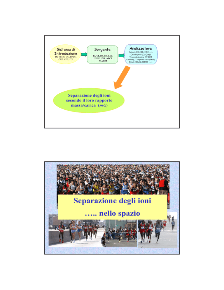
Separazione degli ioni
secondo il loro rapporto
massa/carica (m/z)
Separazione degli ioni
….. nello spazio
Separazione degli ioni
….. nello spazio
Settori: elettrostatico e magnetico
Quadrupolo
Tempo di volo
PRINCIPIO DI FUNZIONAMENTO
DI UN SETTORE MAGNETICO
m0
m0v0
m0v1
m1v0
m1v1
m1
v0
v0 v1
v1
e
sp
di
rs
ion
as
im
d
e
sa
SETTORE ELETTROSTATICO
v1 (m0,m1)
sp
e rs
ion
ed
ie
ne
rg
ia
(m0,m1)v0
di
m0v0
m0v1
m1v0
m1v1
DOPPIO FUOCO
Focalizzazione di un fascio ionico
• divergente
e
• non omogeneo in energia
1974
EBE
EBEBE
1985-1993
Proprietà degli analizzatori:
RISOLUZIONE
∆m
R=
m
___
∆m
Mass spectra recorded at different resolutions: mass spectrum of a mixture of three isobaric species
[C19H7N]+, [C20H9]+, [C13H19N3O2]+ obtained at low resolution (black line) and at resolving power 50,000
(grey line). It is noteworthy that at low resolution the three peaks are completely unresolved.
R=
m
___
∆m
Resolution at 10% valley (left) and at full width at half maximum (FWHM, right).
Summary of some PCDDs mass spectral interferences of environmental origin
∆m = 0.08
PCDDs=polychlorinated dibenzo-p-dioxins
Performances of analyzers:
Mass accuracy
386
386.3
386.35
386.354
386.3549
[C27H46O]+•
MASS ACCURACY
Sectors (BE, EB, EBE,….)
TOF, ORBITRAP, FTICR
Stoichiometry
Exact mass
The calculated mass of an ion or molecule containing a single isotope of each
atom
Accurate mass
An experimentally determined mass of an ion that is used to determine an
elemental formula
Mass Spec Terms Project: http://mass-spec.lsu.edu/msterms/index.php/Category:Mass_spectrometry_terms
VG 70-250S
m/z 900-200
10 sec/dec
Res=8.000 (10% valley)
C34H28N6O4FeS4P2F2
X
X = Reference (PFK)
X
X
X
C 0÷100
H 1÷100
N 0÷8
Fe 0÷1
S 0÷6
F 0÷4
P 0÷4
O 0÷6
X
X
Analizzatori: il quadrupolo
Four rods arranged an equal distance from each other in a parallel manner
rf / -dc
rf 180° out of phase / +dc
Il movimento degli ioni all’interno del quadrupolo dipende da:
1. Il loro rapporto m/z
2. Le dimensioni del quadrupolo
3. Intensità potenziale dc (U)
4. Intensità potenziale rf (V)
5. La frequenza del potenziale rf
http://people.whitman.edu/~dunnivfm/C_MS_Ebook/CH5/5_5_2.html
Hyperbolic rods
Round rods can only approximate the field generated by
hyperbolic rods - most ideal when Rrod/R0 = 1.16.
Manufacturing such a kind of rods is non-trivial
Hyperbolic Rods Quadrupoles
1946
William Stephens at the Univ. of Pennsylvania proposed the concept of
time of flight
Ion source
drift region
In an ideal case, all ions leave the source with the same kinetic
energy:
where V = accelerating voltage, v = ion velocity.
As
where D = drift length and t = the flight time
MW = 1000 Dalton; z=+1; D=1.5m; V=15 kV
t=
1000Da × 1.672621 × 10-27 kg Da-1
2 × 15000 V × 1.602 ×
10-19
× 1.5 m =
C
= 2 .792 × 10-5 s ≈ 28 µs
MW = 10000 Dalton V=15 kV
t ≈ 88 µs
MW = 10000 Dalton V=30 kV
t ≈ 63 µs
MW = 100000 Dalton V=30 kV
t ≈ 20 µs
reflector
+kV
Reflectron
kV
+kV
reflectron
Spiral TOF
The spiral path is composed of 4
layered toroidal electrodes each
incorporating 9 Matsuda plates inside
its cylindrical electrode.
Ions are accelerated to 20 kV in the
ion source, and then pass through
each layer of the 4 layered toroidal
electrodes, reaching the detector.
Ion path = 17m
Separazione degli ioni nello spazio
Analizzatore
Forza
Separazione in base a
Range
m/z
Risoluzione
Massa
accurata
Doppio fuoco (EB, BE)
Campo
magnetico +
campo elettrico
Momento degli ioni +
energia cinetica
10.000
10.000
< 1ppm
Quadrupolo
Campo elettrico
e radiofrequenza
Stabilità/instabilità
2.0004.000
Unitaria
(0.2 u FWHM)
No
(>20ppm)
Velocità
>100.000
>10.000
2-5 ppm
Time of flight
Separazione degli ioni
….. nel tempo
Separazione degli ioni
….. nel tempo
3D
Trappola ionica
2D
Cella a
risonanza
ciclotronica
Orbitrap
The Nobel Prize in Physics 1989
The Royal Swedish Academy of Sciences has awarded this year's Nobel
Prize in Physics for contributions of importance for the development of
atomic precision spectroscopy
Hans Dehmelt
University of
Washington
Seattle, USA
Wolfgang Paul
Universität Bonn
Federal Republic of
Germany
for the development of the
ion trap technique
Norman F. Ramsey
Harvard University
Cambridge, USA
for the invention of the
separated oscillatory
fields method and its
use in the hydrogen
maser and other atomic
clocks
La trappola ionica
Il movimento degli ioni all’interno
della trappola dipende da:
1. Il loro rapporto m/z
2. Le dimensioni della trappola (r)
3. Il potenziale dc (U)
(elettr. anello)
4. Il potenziale rf (V)
(elettr. anello)
5. La frequenza Ω del potenziale
(elettr. anello)
au =
8eU
mr02 Ω 2
qu =
4eV
mr02 Ω 2
Equazione di Mathieu
Analizzatori:
La trappola ionica
rf Amplitude
Electron gate
AM
AC Amplitude
Time
A
τ
B
C
Separazione degli ioni nel tempo
L’elio, presente all’interno della trappola
ionica, aiuta a confinare gli ioni al
centro
Trappola ionica lineare
(2D)
Drive RF &
auxiliary AC
m
37 m
m
12 m
m
12 m
30×0.25mm
Linear Ion Trap
760 torr
ESI source
1.0 torr
1.6 × 10⁻³ torr
2.0 × 10⁻⁵ torr
Heated
capillary
(350°C,20V)
Square quadrupole
(400 Vpp RF,
-6.5 V offset)
Octopole
(400 Vpp RF,
-8.5 V offset)
Front lens
(-21 V)
Back lens
(22 V)
Analizzatori ibridi ….. QqIT
Hybrid Instrument with Q3 Linear Ion Trap
N2 CAD Gas
Skimmer
q0
Orifice
Q1
IQ1
q2
Q3
IQ3
IQ2
LINAC
Exit
linear ion trap
3x10⁻⁵ Torr
Patented Linear Accelerator™ Trap
improved extraction efficiency to yield up
to a 100 x gain in sensitivity in ion trap
scan modes.
20,000 Da/s scan speeds
Improved excitation efficiencies and
reduced ion cooling
high-pressure collision cell accelerates
ions through the collision cell,
increases speed of analysis and
eliminates cross-talk with shorter
transit times across the collision cell
L’espulsione ASSIALE degli ioni permette di accoppiare
la trappola ionica lineare ad altri analizzatori
Electrostatic Traps
“...Static charges can not be stable in electrostatic fields...”
fields...”
Linear traps
Segmented-ring traps
Orbital traps
Kingdon, 1923
The Orbitrap: a new mass spectrometer
Qizhi Hu,a Robert J. Noll,a Hongyan Li,a Alexander Makarov,b Mark
Hardmanc and R. Graham Cooksa∗
a
Purdue University, Chemistry Department, West Lafayette, IN 47907, USA
b
Thermo Electron (Bremen), Hanna-Kunath-Str. 11, Bremen 28199, Germany
c
Thermo Electron (San Jose) 355 River Oaks Parkway, San Jose, CA 95134 USA
JOURNAL OF MASS SPECTROMETRY
J. Mass Spectrom. 2005; 40: 430–443
Standard
High-field
Orbitrap mass
analyzers
Trajectories in the orbitrap
• Characteristic frequencies:
– Frequency of rotation ωφ
– Frequency of radial oscillations ωr
– Frequency of axial oscillations ωz
r
z
ωϕ =
2
ωz
Rm
−1
2 R
2
ωr = ω z
φ
ωz =
U (r , z ) =
{
}
k 2
⋅ z − r 2 / 2 + Rm2 ⋅ ln( r / Rm )
2
Rm
−2
R
k
m/ z
ω=
k
m/ z
1. Frequencies are determined using a Fourier Transformation
2. For higher sensitivity AND resolution, transients should not decay too fast
Ultra-high vacuum
Ultra-high precision
Orbitrap, FT-ICR
LTQ Orbitrap™Hybrid Mass Spectrometer
2005 - 2006
API Ion source
Linear Ion Trap
Differential pumping
C-Trap
Orbitrap
Differential pumping
Inventor: Dr. Alexander Makarov, Thermo Electron (Bremen)
LTQ Orbitrap Operation Principle
1. Ions are stored in the Linear Trap
2. …. are axially ejected
3. …. and trapped in the C-trap
4. …. they are squeezed into a small cloud and injected into the Orbitrap
5. …. where they are electrostatically trapped, while rotating around the central electrode
and performing axial oscillation
The oscillating ions induce an image current into the two
outer halves of the orbitrap, which can be detected using
a differential amplifier
Ions of only one mass generate a sine
wave signal
Frequencies and Masses
The axial oscillation frequency follows the formula ω =
ω = oscillation frequency
Where
k = instrumental constant
m/z = …. well, we have seen this before
Many ions in the Orbitrap generate a complex
signal whose frequencies are determined using a
Fourier Transformation
k
m/ z
Orbitrap Exactive
Orbitrap Q Exactive
Orbitrap Velos
Orbitrap Elite
Orbitrap Fusion – Minneapolis 2013
2D-IT
Orbitrap
Relative Abundance
Cytochrome C Zoom on the 8+
100
95
90
85
80
75
70
65
60
55
50
45
40
35
30
25
20
15
10
5
0
1544.5
1545.79939
1545.92433
1545.67426
1546.04924
1545.54955
1546.17434
1545.42465
1546.29941
1546.42454
1545.29905
1546.54971
1545.17502
1545.0
1546.67458
1545.5
1546.0
m/z
1546.5
1547.0
1547.5
Fourier Transform Ion Cyclotron Resonance Mass Spectrometry
http://www.youtube.com/watch?v=7EHngA4S3Ws
Movimento Ciclotronico
Per mantenere lo ione in un’orbita circolare stabile occorre che:
Ne consegue che la frequenza angolare ω di uno ione con massa m e
carica q è data da:
v/r = q B/m
Frequenza ciclotronica ω
ω = q B/m
(radianti/sec)
ω = (q B/m)/2π
(Hz)
Da notare che la frequenza ciclotronica NON dipende dalla velocità dello ione.
Perciò ioni di una stessa massa avranno tutti la stessa frequenza ciclotronica
indipendentemente dal tempo in cui entrano nella cella o dalla velocità con
cui vi entrano.
Ad esempio, la frequenza ciclotronica di uno ione monocaricato, con m/z
1000 e un campo magnetico di 7.0 Tesla, è di 107.45 kHz, ovvero compie
circa 100.000 orbite al secondo.
Se il suo stato di carica è +4 il numero di orbite al secondo diventa circa
400.000.
La cella è situata all’interno di una regione di campo omogeneo di un grande magnete
superconduttore. Gli ioni si muovono in orbite circolari alle loro frequenze ciclotroniche.
Se all’interno della cella vi sono ioni con diverso valore di m/z, essi gireranno su orbite con
un raggio molto simile ma avranno frequenze diverse.
Normalmente il raggio di un’orbita di uno ione è di circa 0.1 mm.
Se un impulso RF, sufficientemente largo (8MHz÷100kHz) da coprire l’intervallo delle
diverse frequenze ciclotroniche degli ioni che si vogliono osservare, viene inviato
all’interno della cella, gli ioni acquisteranno energia dal campo RF e si muoveranno su
orbite più larghe.
Così il segnale complessivo che esce dalla cella è un segnale composito costituito dalla
sovrapposizione delle frequenze ciclotroniche di tutti gli ioni presenti all’interno.
Inoltre questo segnale diminuisce lentamente mentre gli ioni rilassano e ritornano alle loro
orbite circolari stabili al centro della cella.
Usando la trasformata di Fourier è possibile deconvolvere il segnale complessivo e
identificare le singole frequenze.
A new ultra-high resolution FT-ICR cell with dynamic harmonization
extreme mass resolution greater than 10 million
Nikolaev EN, Boldin IA, Jertz R, Baykut G., J Am Soc Mass Spectrom. 2011, 22:1125-33
Qq-FTICR
IT-FTICR
ESI (+) of Ubiquitin
1,040,000 Resolution at m/z 779
0.09u
0.09u


