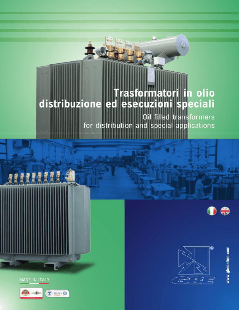
Trasformatori in olio
distribuzione ed esecuzioni speciali
MADE IN ITALY
www.gbeonline.com
Oil filled transformers
for distribution and special applications
2
A dynamic and efficient team
Una Realtà Dinamica ed efficiente
ENG
In a continuously expanding and developing world
where it is required to be competitive and dynamic
in every market, the company shall give evidence of
its skills providing constantly state of art products
that fulfils the markets’ request.
Being in the business as we put it here in GBE
does not lie as much in waiting for replies from
the market, but rather in proposing themselves,
understanding the demands, evaluating the needs
and at the customers’ side offering more than
required by constantly calling themselves into
question so to increase and improve.
GBE desire to show how not only the Italian Design
but also the Italian Technology could be appreciated
worldwide as long as the demand is seriously dealt
with commitment and maximum availability to work
as a great one-team.
Mission
In un mondo in continua espansione e sviluppo
dove in ogni mercato si deve essere competitivi e
dinamici, l’azienda deve dar prova e dimostrazione
delle proprie capacità proponendo un prodotto
sempre nuovo e che soddisfi pienamente le richieste
del mercato.
Fare impresa così come lo intendiamo in GBE, non
significa tanto attendere risposte dal mercato, quanto
proporsi, capire le esigenze, valutare le necessità e,
sempre dalla parte del cliente, offrire più di quanto
richiesto, mettendosi continuamente in discussione
per poter crescere e migliorare.
GBE desidera dimostrare come non solo il design ma
anche la tecnologia italiana possa essere apprezzata
in tutto il mondo, qualora la richiesta sia affrontata
con serietà, impegno e massima disponibilità di un
team unito.
GBE S.p.A. is specialized in manufacturing of oil
filled transformers from 50 kVA up to 50 MVA,
145 kV (BIL 650 kV). Furthermore we offer oil filled
reactors from few kVAR up to 10 MVAR.
Our experience in the field has enabled us to solve a
wide range of requirements even for special units, i.e.
converter transformers with 6-12-18-24-36 pulse,
earthling transformers with and without auxiliaries,
transformers for solar plants with 1-2-3 secondary
windings, HV/HV transformers, multi voltage
transformers, transformers with different type of oil:
Silicon type, MIDEL, FR3. Shunt reactors, current
limiting, damping, tuning (filter), arc-suppression,
smoothing reactors, LV/MV/HV reactors up to 52 kV.
GBE S.p.A. are present in the national and
international market and count on a 25-year technical
experience in the field. The recently built new works
are equipped with high-tech producing plants, the
most sophisticated automation job order systems
via real time production management.
ENG
ITA
ITA
La GBE S.p.A. è specializzata nella produzione di
trasformatori in olio da 50 kVA fino a 50 MVA, 145
kVA (BIL 650 kV). Inoltre produce reattanze in olio
da alcuni kVAR fino a 10 MVAR.
L'esperienza acquisita ci ha permesso finora
di risolvere le più svariate richieste anche per
unità speciali quali: trasformatori per impianti di
conversione a 6-12-18-24-36 pulse, trasformatori di
messa a terra con e senza ausiliare, trasformatori
per impianti solari con 1-2-3 secondari, trasformatori
MT/MT, trasformatori multitensione, Trasformatori
con olio siliconico; MIDEL o FR3. Reattori in olio di
corto circuito, limitatrici, spianatrici, filtri, reattori di
bassa, media e alta tensione fino a 52 kV.
GBE opera direttamente sul mercato nazionale ed
estero e si avvale di 25 anni di esperienza tecnica
nel settore. Lo stabilimento di recente costruzione
è munito di tutte le attrezzature e macchinari più
sofisticati, con processi produttivi automatizzati ed
una gestione della produzione in tempo reale tramite
codifica delle commesse e bar-code per i materiali.
3
Magnetic core
ENG
ITA
Nucleo magnetico
4
Il nucleo dei trasformatori GBE è costruito con
lamierino magnetico a grani orientati ad alta
permeabilità magnetica e a perdite specifiche isolati
in ambo i lati da un sottile spessore di materiale
inorganico (Carlyte).
Il taglio e la composizione è del tipo a 45° a giunti
intercalati con metodo “Step-Lap” in modo da ridurre
le perdite a vuoto, la corrente a vuoto e la rumorosità
del trasformatore. Il numero di gradini e il valore di
induzione sono ottimizzati in funzione della potenza
del trasformatore. Il serraggio è ottenuto da profili
in acciaio zincato opportunamente dimensionati in
grado di garantire robustezza e staticità adeguate
per tutte le sollecitazioni derivanti dalle operazioni
di trasporto e scarico, dagli sforzi elettrodinamici e
dalle installazioni più difficili.
GBE transformers cores are obtained from cold rolled
grain oriented (CRGO) magnetic steel sheets with
highly magnetic permeability and insulated on both
sides with a thin layer of inorganic material (Carlyte).
The sheet cut and the composition at 45° with “Step
Lap” intercalated joints guarantee reduced no-load
losses, reduced idling current and low noise level.
The number of steps and the magnetic induction are
optimized for the power of the transformer. The top
and bottom clamps are made by galvanized steel
designed as to guarantee the necessary strength
for all movements during transport and unloading,
electro dynamic stresses and the most difficult
installations.
Oil filled transformers
GBE S.p.A. produce oil filled transformers for
different applications, particularly for distribution
and special apply with the power up to 50 MVA, also
with unload tap changer. The transformer windings
are concentric and coaxial to the core limbs. The
windings are made of copper or aluminum with
insulation material in class A or F. Channels in the
windings guarantee oil circulation and windings
optimal cooling.
All transformers up to 3150 kVA are equipped with
corrugated tank wall panels. Higher power units use
special developed radiators made with cold rolled
and laminated steel. All transformers up to 3150 kVA
can be filled without conservator.
The outside walls are protected with water resistant
paint RAL 7031 or RAL 7033 with painting thickness
of minimum 100 micron. Furthermore GBE S.p.A.
offer customized tanks in request.
Trasformatori in olio
ENG
ITA
GBE S.p.A. produce trasformatori in olio per tutte
le applicazioni, in particolare trasformatori per la
distribuzione e speciali con potenza fino a 50 MVA,
anche con commutatore sotto carico.Gli avvolgimenti
dei trasformatori sono coassiali alle colonne del
nucleo e di tipo concentrico. Possono essere realizzati
in rame o alluminio con isolamento in classe A o
F. Gli avvolgimenti possono presentare dei canali
per la circolazione del olio e quindi raffreddamento
degli stessi. Questi avvolgimenti sono a sezione
ovale o circolare e del tipo concentrico, coassiali alle
colonne del nucleo. La cassa dei trasformatori fino
a 3150 kVA e del tipo a onde elastiche. Per potenze
superiori sono previsti radiatori in lamiera stampata
e laminata a freddo. Se previsto i trasformatori sono
dotati di normale conservatore per l’espansione
dell’olio.
La cassa é protetta dalla vernice idrosolubile RAL
7031 o RAL 7033 con spessore di verniciatura
100-120 micron. Inoltre la GBE S.p.A offre casse
personalizzate su richiesta.
Informazioni generali
Tutta la produzione è realizzata in conformità alle
norme di riferimento europeo CEI, IEC, CENELEC,
DIN, BRITISH STANDARD, UNI EN, ISO ed altre.
Diverse sono le omologazioni e le certificazioni di
prodotto ottenute fino ad ora: RINA, DNV, Lloyd's
Register e altri. La GBE è certificata ISO 9001:2008
e ISO 14001.
ENG
ITA
General information
The whole GBE production is manufactured
according to European Standards CEI, IEC, CENELEC,
DIN, BRITISH STANDARD, UNI EN, ISO and more.
Various are GBE recognitions and certifications
such as RINA, DNV, LLOYD'S REGISTER and other
naval and marine recognitions. GBE S.p.A. is ISO
9001:2008 and ISO 14001 certified.
5
ENG
ITA
Technical characteristics
Caratteristiche tecniche
6
Accessori del trasformatore
Transformer Accessories
1 Morsetti di Terra
2 Isolatori di Bassa Tensione
3 Commutatore regolazione
4 Tubo riempimento olio con valvola antiscoppio
5 Marshaling Box (su richiesta)
6 Tappo riempimento
7 Conservatore (se non è ermetico)
8 Relè Buchholz
9 Termometro a due contatti elettrici (su richiesta)
10 Golfari di sollevamento
11 Pozzetto termometrico
12Carrello
13 Avvolgimento di media tensione
14 Ruote orientabili ortogonalmente
15Nucleo
16 Valvola di scarico
17 Avvolgimenti di Bassa Tensione
18 Tappi di pressaggio
19Serrapacchi
20 Indicatore del livello olio (se non ermetico)
21 Isolatori di Media Tensione
22 Silicagel (se non è ermetico)
23 Cassa a onde
24 Attacchi Elastimold (su richiesta)
25 Massa sulla cassa
26 Targa con dati tecnici
27 Golfari di traslazione
1 Earthing terminals
2 Low Voltage Bushings
3 Off load tap changer
4 Filling pipe with antibrust valve
5 Marshaling Box
6 Filling tap
7 Conservator (if not hermetic)
8 Rele’ Buchholz
9 Thermometer with two electric contacts (upon request)
10 Lifting eyebolts
11 Thermometer pocket
12Truck
13 Medium Voltage Windings
14 Swivelling rollers
15 Magnetic Core
16 Oil discharge and extraction valve
17 Low Voltage Windings
18 Pressing Plugs
19Clamps
20 Oil level indicator (if not hermetic)
21 Medium Voltage Bushings
22 Silica gel connection (if not hermetic)
23 Tank with waves
24 Elastimold (upon request)
25 Earthing point on tank
26 Name plate
27 Movement eyebolts
Accessori di Corredo su richiesta
Further Accessories available upon request
•
•
•
•
•
•
•
•
•
DGPT2 o RIS (se ermetico)
•
Barre passanti per la Bassa Tensione
•
Valvola antiscopio con contatti
•
Immagine termica
•
Cable box per la bassa e media tensione
•
Oil level indicator with contacts (se non ermetico)
•
Sonde PT100 per il controllo della temperature di olio (PTO) •
Scaricatori a corno
•
Altri (vedi costruttore)
•
DGPT2 or RIS (if airtight)
LV extension bars
Antibrust valve with contacts
Thermal image
Cable box (HV / LV)
Oil level indicator with contacts (if not hermetic)
PT100 sensors for oil temperature control (PTO)
Horn arrestor
Others (see Manufacturer)
High voltage & low voltage windings
The primary and secondary windings are made with
electrolytic aluminum or copper, with insulation in
pure cellulose paper or in double enamel for wires of
small diameter. These windings are oval or circular
section and are a concentric type, coaxial to the core
columns. The high voltage winding is made with a
wire or a metal strip, helically wound with more
layers or with continuous disc in relationship to the
working voltage and the transformer's power. The
low voltage windings are made with foil or strip and
are equipped with terminal bars welded along the
whole coil length in order to guarantee the correct
sturdiness and electro-mechanical stress. Each
winding layer of low and medium voltage is insulated
with pure cellulose paper, the oil's circulation and
necessary cooling are assured by wide channels
placed between the windings layers. Insulation
between high and low voltage and between the latter
and the core is made with compressed cardboard
cylinders with a well-sized thickness.
Avvolgimenti di alta e bassa tensione
ENG
ITA
Gli avvolgimenti primari e secondari dei trasformatori
in olio sono costruiti in alluminio e/o rame
elettrolitico con isolamento dei conduttori in carta
di pura cellulosa o per fili di piccolo diametro, in
smalto doppio. Questi avvolgimenti sono a sezione
ovale o circolare e del tipo concentrico, coassiali
alle colonne del nucleo. L’avvolgimento di alta
tensione è realizzato in filo o piattina, avvolto ad
elica in più strati o a disco continuo in relazione alle
tensioni d’esercizio e alla potenza del trasformatore.
Avvolgimento di bassa tensione è realizzato in lastra
e piattina e presenta i terminali eseguiti in piatto
saldato in tutta la lunghezza dell'avvolgimento che ne
garantisce la robustezza e resistenza alle sollecitazioni
elettrodinamiche. Ogni strato degli avvolgimenti di
alta e bassa tensione è isolato con carta di pura
cellulosa. Ampi canali, posti tra gli strati degli
avvolgimenti, assicurano la circolazione dell’olio ed
il necessario raffreddamento. L’isolamento tra alta e
bassa tensione e tra questa ed il nucleo è effettuato
con cilindri di cartogeno precompresso di spessore
adeguato.
7
Commutatori per la regolazione
e per variazione della tensione primaria
La regolazione e la variazione della tensione primaria
è effettuata con commutatori lineari immersi nell’olio
e manovrabili a trasformatore disinserito dalla rete
mediante manopole poste sul coperchio. Per evitare
un errato posizionamento dei commutatori sono
previsti dei fori in corrispondenza di ogni tacca di
indicazione delle varie posizioni che consentono un
sicuro alloggiamento della manopola.
Se richiesto il trasformatore può essere dotato di
commutatore a carico che consente la variazione
con trasformatore in funzionamento delle tensioni
di regolazione.
GBE S.p.A. può realizzare trasformatori con tutte le
marche di commutatori presenti sul mercato e fino
a basse potenze.
8
ENG
ITA
Tap changers for adjustement or variation of primary voltage
The adjustment or variation of primary voltage is
done with linear tap changers in an oil bath and
maneuverable with the transformer disconnected
from the network by using knobs placed on the
cover. To avoid an incorrect positioning of the tapchangers, are foreseen some holes in correspondence
with each indication notch of the various positions
that allow a secure housing of the knob; in addition,
it is possible to apply a padlock to avoid accidental
or unauthorized maneuvers.
If required, the transformer may also be equipped
with on-load tap changer, which regulates the voltage
variation with working (energized) transformer.
GBE S.p.A. offer transformers equipped with any
make of on-load tap changer in the market also for
small power range.
The insulators
Isolatori
Insulating liquid
ENG
The filling of the transformers is obtained with
mineral oil, without PBC, dried and degassed,
with electrical and chemical specifications, which
conform to the CEI and IEC standards; the filling is
done under-vacuum for the best oil electrical rigidity
withstand. If required the tank can be filled with
silicon type dialectric oil, MIDEL or FR3.
Liquido isolante
Il riempimento del trasformatore è ottenuto con
olio minerale dielettrico esente da PCB, essiccato e
degasato, con caratteristiche chimiche ed elettriche
conformi alle norme CEI in vigore: il riempimento
è effettuato sotto vuoto per la massima tenuta
elettrica della rigidità elettrica dell’olio. A richiesta il
riempimento può essere effettuato con olio dielettrico
di tipo siliconico, MIDEL o FR3.
The high and low voltage bushings are oil filled
type in enameled brown porcelain according IEC
standards. The insulators are fixed on the conver
with special frames and and may be substituted
without removing the core and coil assembly. High
voltage bushings may be equipped on request with
spark gap rods. The high voltage bushings are
provided with spark grip rods. Cast resin insulators
suitable for Elastimold type connectors can be
delivered upon request.
For the whole range of GBE oil immersed products
we have studied, developed and designed new
gaskets for outdoor installation bushings that are:
from -60°C, -40°C, -25°C up to 120°C or 150°C.
ENG
ITA
ITA
Gli isolatori passanti di alta e bassa tensione sono del
tipo per esterno in porcellana smaltata color bruno
riempiti d’olio e conformi alla normativa IEC. Gli
isolatori sono fissati sul coperchio mediante appositi
telai e sono sostituibili senza estrarre il frutto dalla
cassa. Gli isolatori di alta tensione su richiesta
possono essere muniti di aste spinterometriche.
Gli isolatori di alta tensione sono muniti di aste
spinterometriche. Gli isolatori possono essere anche
in resina per attacco Elastimold oppure passanti.
Per tutta la gamma dei prodotti GBE in olio sono
state studiate, progettate e sviluppate delle nuove
guarnizioni per isolatori per applicazione esterna: da
-60°C, -40°C, -25°C fino a 120°C oppure 150°C.
9
Standard accessories
ENG
ITA
Accessori d’uso
10
Tutti i trasformatori sono dotati dei seguenti
accessori standard:
• Conservatore dell’olio sopra il coperchio (per
trasformatori non ermetici)
• Indicatore di livello montato sul conservatore
(per trasformatori non ermetici)
• Commutatore a vuoto sopra il coperchio per
regolazione della tensione primaria del ± 2x2,5%
• n°3 isolatori in porcellana lato MT (DIN 42 531)
• n°3 isolatori in porcellana lato BT + n°1 isolatore
in porcellana per il neutro (DIN 42530)
• Valvola di riempimento olio
• Valvola di scarico olio (DIN 42 551)
• n°4 ruote di scorrimento orientabili
ortogonalmente (DIN 42 561)
• n°1 targa caratteristiche IEC 60076
• Golfari di sollevamento
• n°2 morsetti di terra
• Pozzetto/i termometrico/i (DIN 42 554)
All our transformers are equipped with following
standard accessories:
•Oil conservator mounted on the tank top cover
(for non hermetically sealed transformers)
•Oil level indicator on the conservator
(for non hermetically sealed transformers)
•MV regulation tappings ± 2x2,5% wired to
off-circuit tap changing switch with external
operating handle
•MV screwed, fully insulated porcelain bushings, 3
off, (DIN 42 531) requirements
•LV Porcelain bushings, 3 off line terminals plus
Neutral bushing, (DIN 42530) requirements
•Oil filler cap
•Oil drain valve (DIN 42 551) requirements
•n°4 bi-directional floor rollers (DIN 42 561)
requirements
•n°1 rating and name plate (IEC 60076)
requirements
•Lifting lugs/eyebolts
•n°2 earthing terminals
•Thermometer pocket in accordance (DIN 42 554)
The tank
ITA
ENG
La cassa dei trasformatori può essere del tipo a
onde elastiche oppure con radiatori in lamiera
stampata e laminata a freddo. I radiatori sono
provati singolarmente prima del loro montaggio.
Se previsto i trasformatori sono dotati di normale
conservatore per l’espansione dell’olio a caldo. Per
trasformatori fino a 4000 KVA è possibile la soluzione
a riempimento integrale senza conservatore. Le parti
interne delle casse sono protette, previa sabbiatura,
con speciali vernici insolubili all’olio caldo. Le pareti
esterne subiscono un ciclo protettivo con vernice
idrosolubile, RAL 7031 o RAL 7033 con spessore di
verniciatura 100-120 micron, e sono adatte alle più
severe condizioni ambientali.
Cassa
The transformer tank is available in two versions:
corrugated (finned) tank or with radiators, made
with cold rolled and laminated steel. All radiators are
singularly tested before their assembling. If required
the transformer may be supplied with a traditional
expansion conservator. All transformers up to 4000
KV can be filled without conservator. The inside
walls of tanks are protected, prior to sand blasting,
with special paint insoluble to hot oil. The outside
walls are protected with water resistant paint RAL
7031 or RAL 7033 with painting thickness of 100120 micron, suitable to the strictest environmental
conditions.
11
Accessories upon request
ENG
ITA
Accessori a richiesta
12
Ove richiesto, è possibile equipaggiare i
trasformatori dei seguenti accessori:
• Relè buchholz di protezione a 2 contatti (per
trasformatori non ermetici)
• Essiccatore d’aria al silicagel completo di carica
sali (per trasformatori non ermetici)
• Presenza contatti per indicatore di livello olio (per
trasformatori non ermetici)
•Valvola di sovrapressione (per trasformatori
ermetici)
• Sistema di protezione integrato DGPT2 o RIS
(per trasformatori ermetici)
• Termometro a quadrante a 2 contatti elettrici
• Cassonetto di protezione IP55 per isolatori BT
• Cassonetto di protezione IP55 per isolatori MT
• Set antivibranti
• Relè di pressione a 2 contatti
• Schermo elettrostatico tra primario e secondario
• Slitte per appoggio su palo
On request following additional accessories can be
delivered:
•Gas and oil operated Buchholz relay with 2
electrical contacts
• Dehydrating breather (for non hermetically sealed
transformers)
• Oil level indicator contacts on the conservator
(for non hermetically sealed transformers)
• Pressure relief valve (hermetically sealed
transformers)
• Protection system DGPT2 or RIS (for hermetically
sealed transformers)
• Thermometer with 2 electrical contacts
• Protection housing IP 55 for LV bushings
• Protection housing IP 55 for MV bushings
• Antivibration pads for wheels
• Pressure relay with 2 electrical contacts
• Electrostatic screen between primary and
secondary voltage
• Skids for pole mounted transformers
13
14
Finished products
Prodotti finiti
Tutta la produzione GBE è progettata e costruita in
conformità alle seguenti norme:
All our products are designed and manufactured
according the following rules:
•
•
•
•
•
•
•
•
•
•
•
•
IEC 60076;
EN 50464;
IEC 61378-1
EN 50216
ISO 9001:2008
ISO 14001:2004
IEC 60076;
EN 50464;
IEC 61378-1
EN 50216
ISO 9001:2008
ISO 14001:2004
Test reports & witnessed tests
Quality of GBE products
Quality of GBE products
Qualità del prodotto GBE
Qualità del prodotto GBE
All transformers are tested in our test-room
according IEC 60076 norms. All transformers are
delivered with maintenance manual, test report,
technical drawing and all necessary certifications.
the offer to the after sale service.
GBE S.p.A. has test room with very high level
equipment. We are able to make all acceptance
tesst, without any exception. Our test room is
equiped with special converter 400 A up to 12000V
and permits to change the frequency up to 400 Hz.
Furthermore there is a impluse test device, which
guarantees impuls test range up to 1.200.000 V.
All our products are manufactured according to ISO
9001:2008 and ISO 14001:2004.
Prove e collaudo
ENG
ITA
Tutti i trasformatori sono sottoposti presso la
nostra sala prove ai collaudi secondo le norme IEC
60076. Sono inoltre corredati di manuale d’uso e
manutenzione, bollettino di collaudo, certificato di
conformità e disegni d’ingombro.
GBE S.p.A. dispone di una sala prove altamente
avanzata. Siamo in grado di fare tutte le prove
di accettazione, nessuna esclusa. La sala prove
dispone di un convertitore 400 A fino a 12000 V
con possibilità di variare la frequenza fino a 400
Hz. Inoltre siamo in possesso di uno strumento la
prova d’impulso fino a 1.200.000 V.
La nostra produzione è certificata secondo le norme
ISO 9001:2008 e la ISO 14001:2004.
15
stage.
Livello Isolamento MT / Rated Voltage HV
Norme
Livello Isolamento BT / Rated Voltage
LV
Uk 4%
Uk 6%
TS3R07-TS3R12 (CoBk)
50
100
160
200
250
315
400
500
630
4
4
4
4
4
4
4
4
4
300
440
610
715
820
960
1150
1300
1500
1250
1700
2300
2700
3000
3600
4300
5300
6400
50
100
160
200
250
315
400
500
630
6
6
6
6
6
6
6
6
6
380
440
610
700
820
950
1150
1300
1500
1400
1800
2400
2800
3100
3700
4400
5400
6500
800
6
1800
1000
6
2100
6
1600
A
B
C
LwA Isolamento
LpA
Classe
BT / Insulation Class LV
(mm)
(mm)
(mm)
(dB(A)) (dB(A))
D
FI 3 kVKg
(mm)
1600
2000
2700
3100
3500
4200
4900
6100
7300
1,92
1,68
1,6
1,5
1,42
1,3
1,18
0,96
0,85
8000
9000
8800
10000
2500
10700
6
2800
2000
6
2500
Regolazione MT / Tappings HV
48
50
53
54
55
57
58
58
59
1040
1040
1120
1230
1270
1300
1300
1380
1410
670
670
670
670
670
820
820
820
820
1100
1150
1200
1300
1300
1400
1500
1550
1650
47
59
62
64
65
67
68
69
70
39
50
53
55
55
57
58
59
59
1040
1120
1120
1230
1270
1300
1330
1380
1410
670
670
670
670
670
820
820
820
820
0,72
71
60
1460
0,64
73
62
1510
12000
0,56
75
63
12700
14500
0,52
76
3600
16000
18000
0,48
6
4300
18000
21000
3150
6
5300
22900
4000
7÷8
pcc
(75°C)
7÷8
6800
Uk
25600
po
(W)
(W)
7500
(75°C)
%
± 4% or ± 2x2,5%
520
520
520
520
520
670
670
670
670
400
520
750
870
1010
1150
1340
1590
1820
900
1100
1150
1200
1300
1300
1400
1500
1550
520
520
520
520
520
670
670
670
670
380
500
720
840
970
1100
1290
1530
1760
1000
1650
820
2080
1000
1750
820
2480
1620
1000
1850
820
2870
64
1640
1000
2150
820
3350
78
66
1710
1300
2150
1070
3950
0,45
81
68
1790
1300
2250
1070
4700
26000
0,4
83
70
2060
1300
2450
1070
5640
28780
0,32
84
70
2500
p
2680
(mm)
1070
J
1250
(mm)
7700
G
9600
(mm)
520 900
520 1100
520 1150
520 1200
670 1300
670 1300
670 1400
670 1500
670 1550
670 1700
820 1750
820 1950
820 2200
1070 2250
1070
2300
265
520 265 520
265 520
265
520 265
520 265
670 265
670 265
670 265
670 265
820 265 820
265 820
265 820 265
1070
265 1070
1070
1070
1250
90
400
90
530
90
760
120
880
120
1020
120
1160
120
1360
130
1610
130
1850
130
2190
150
2610
150
3020
180
3530
180
4160
220
4950
5940
8100
10100
2150
1300
lwA
Total
A
b
C
D
M
oil
28400
31950
0,29
85
71
2260
1500
dB(A)
(kg)
(kg)
(mm)
(mm)
(mm)
(mm)
(mm)
PERDITE
STANDARD
24 kV10357201365
/ STANDARD LOSSES
24 kV265 90
100320
2150
4 59CLASSE
580 150
980CLASS
125 520
160 460
3100
4
62
750 180 1095
730
1445
1060
125
520
265
FI 50 kV90BIL
Classe Isolamento MT / Insulation Class HV
Livello
Isolamento MT / Rated Voltage HV
24 kV
200550 3640 4 64 870 240 116581514901105125 520 265
95 kV90
250 650 4200 4
65 1010 230 1225 845 1490 1105 125 520 265 120
Livello Isolamento BT / Rated Voltage LV
Classe Isolamento BT / Insulation Class LV
FI 3 kV
1,1 kV
315 770 5000 4
67 1170 260 1255 870 1530 1145 125 670 265 120
400 Frequenza
930 6000
4
68 133050÷60
300
1675 MT 1290
125
670 265± 2 x 2,5%
120
/ Frequency
Regolazione
/ Tappings
HV
Hz 1255 870
500 1100 7200 4
69 1500 330 1320 870 1675 1290 125 670 265 120
Pcc 380 I 1360 870 1785 A1400 B125 Uk 630 1300 8400
4Po
70Pcc
1780
670
265
130
C D LwA
LpA
0
Kg
GBE (75°C) CEI-EN (120°C)
630 KVA
1200 (120°C)
8700 6
70 1770 430 % 1455
885 (dB(A))
1715 (mm)
1330 (mm)
125 (mm)
670 (mm)
265 130
(W)
(dB(A))
(W)
(W)
%
800 1400 10500 6 71 2030 480 1730 885 1785 1400 125 670 265 130
50 13000
4
1570
520 430
1000 1700
300
6
731400
2400
5502,74
1810 58 1110 491870 1040
1485 670
150 1100
820 265
150
4
1600
1750
520 570
1250 100
2100 16000
400
6
74
2760
6202,15
1850 59 1110 501950 1040
1565 670
150 1150
820 265
150
160 20000
4
2200
2500
520 820
1600 2600
580
6
76
3350
7901,97
2020 62 1110 532015 1070
1630 670
150 1200
820 265
180
200 26000
4
2600
2980
520 950
2000 3100
690
6
78
4120
9501,92
2170 64 1380 542190 1250
1805 670
200 1300
1070 265
180
250 32000
4
3450
520 1100
2500 3500
800
6
813000
4910
11401,73
2285 65 1380 552305 1250
1920 670
200 1300
1070 265
220
315
4
950
3700
4170
1,72
67
57
1250
820
1400
670
1250
400
4
1100
4400
4900
1,51
68
58
1330
820
1500
670
1470
pcc
Uk
lwA
p
J
G
po
500
4
1350
4900 Total
5550 oil 1,16 A 69 b
58 C 1330D
820M
1550
670
1740
(75°C)
KvA
(75°C)
dB(A)
(kg)
(kg)
(mm) 820
(mm) 1650
(mm)
(mm)
(mm)
(W)
(W)
630
4
1600
6100
6900
1,08 (mm) 70 (mm) 59(mm) 1360
670
2000
%
Uk 4%
TE3024 - TE3012 - EoDk (ex BA')
2 x 2,5%
FI±28÷50
kV
BIL 75÷125 kV
57
59
62
64
65
67
68
69
70
5000
FI 3 KV
Regolazione MT / Tappings HV
Classe Isolamento MT / Insulation Class HV
2,43
1,91
1,75
1,71
1,54
1,53
1,34
1,17
0,96
100 160 200 250 315 400 500 630 630 800 1000 1250 1600 2000 2500 210 50
300 100
370 160
425 200
520 250
610 315
720 400
860 500
800 630
930 800
1100 1000
1350 1250
1700 1600
2100 2000
2500 2500
3150
16
50÷60 Hz
12÷24 kV
Pcc
I0
kV
CEI-EN1,1
(120°C)
%
(W)
50÷60 hz
1420
2000
2700
3050
3500
4100
4900
5950
7300
X=300÷600 mm1250
28 kV BIL
75 kV
/ standards
CEI EN BT
50464
Classe –Isolamento
/ Insulation Class LV
1,1 kV CEI EN 60076
Pcc
Uk
Po
Livello Isolamento
BT
/ Rated Voltage
LV
GBE (75°C)
KVA
(120°C)
(W)
(W)
%
Frequenza / Frequency
KvA
Classe Isolamento MT / Insulation Class HV
12 kV
Frequenza / Frequency
Livello Isolamento MT / Rated Voltage HV
Uk 6%
Characteristic are
indicative. GBE
will confirm actual
data at offer/order
PERDITE STANDARD CLASSE 12 kV / STANDARD LOSSES CLASS 12 kV
TZ3024 - TZ3012 - CoDk (ex bC’)
TS3R17-TS3R24 (CoBk)
Technical data sheet series EoDk (ex BA')- CoDk (ex BC')
Standard line with losses according to EN 50541 - 1/2011
Scheda
serie
EoDk (ex BA')
CoDk (ex- BC')
Serietecnica
perdite
standard
EN -50541
1/2011
Dati e
caratteristiche sono
indicativi e non
impegnativi. La
GBE si riserva di
comunicare i dati
effettivi in fase di
offerta.
Norme / Standards IEC 60076 – CEI EN 60076 – DIN EN 60076 – EN50541-1
4000
5000
2150
6 3100 6
3640 6
4200
6 5000
6 6000
6 7200
6 8400
6 8700
6 10500
6
13000 6
16000 6
20000 6
26000
6
32000
6
6
7÷8
7÷8
4
360
4
460
4
650
4
770
4
880
4
1050
4
1200
4
1450
6
1650
6
2000
6
2300
6
2800
6
3100
6
4000
6
5000
6000
7000
8100
49
1600
52 1800
54 2600
55
3000
57
3300
58
4100
59
4800
60
5800
606800
618300
63 9600
64 11500
66
14000
68
16000
71
20000
23500
26600
29400
590
1750
750 2050
880 2900
1020
3350
1190
3800
1340
4650
1520
5500
1790
6550
1780
7600
2050
9400
2420 11000
2790
13000
3380 16000
4170
18000
4960
23000
28000
29930
33100
140 2,4
180 2,1
240 2
2301,87
2601,78
3001,65
3301,48
380 1,2
4201,06
480 0,9
550 0,8
620 0,7
790 0,65
940 1140 0,6
0,56
0,5
0,4
0,36
1035
1095
1165
1225
1255
1255
1320
1360
1455
1730
1810
1850
2020
2170
2285
58
59
62
64
65
67
68
69
70
72
73
75
76
78
81
83
86
88
720 501365
730 1445
50
815 1490
53
845 551490
870 551530
870 571675
870 581675
870 591785
885 591715
885 611785
1110 1870
62
1110 1950
63
1110 2015
1380 632190
1380 652305
68
70
72
74
1040980 1060 1070
1105 1250
1250
1105 1250
1145 1330
1290 1330
1290 1360
1400 1410
1330 1570
1400 1485 1570
1565 1740
1630 1740
1805 1860
1920 2010
2100
2260
2380
125
670
125
670
125
670
125
670
125
670
125
820
125
820
125
820
125
820
125
1000
150
1000
150
1000
150
1000
200
1300
200
1300
1300
2450
1300
2500
1500
2680
Livello Isolamento MT / Rated Voltage HV
Livello Isolamento BT / Rated VoltageNorme
LV
Frequenza / Frequency
Livello Isolamento MT / Rated Voltage HV
TD3R07-TD3R12 (BoBk)
Uk 4%
Uk
Po VoltagePcc
Livello KVA
Isolamento
BT / Rated
LV
GBE (75°C)
(120°C)
(W)
(W)
%
Frequenza / Frequency
50
100
160
200
250
315
400
500
630
Uk 6%
50
100
160
200
250
315
400
X=300÷600500
mm
630
4
4
4
4
4
4
4
4
4
230
330
450
540
610
750
880
1020
1150
1250
1700
2300
2700
3000
3600
4300
5300
6400
6
6
6
6
6
6
6
6
6
290
330
450
540
610
730
880
1000
1150
1400
1800
2400
2800
3100
3700
4400
5400
6500
6 pcc 1300Uk 8000
lwA
(75°C)
(75°C) dB(A)
(W) 6 (W) 1500 % 8800
1250
6
1800
10700
100 320 1750 4
59 1600
6
2200
12700
160 460 2350 4
62 2000
6
2600
16000
200 550 2800 4
64 2502500
650 6 3250 3200
4 18000
65 3153150
770 6 3900 3800
4 22900
67 4004000
930 7÷8 4600 5240
4 25600
68 5005000
1100 7÷8 5500 5780
4 28400
69 630 1300 6500 4
70 630 1200 6750 6
70 800 1400 8400 6
71 Livello
Isolamento
Rated Voltage
1000
1700 MT
/10500
6 HV 73 1250 2100 13500 6 74 Livello
Isolamento
Rated Voltage
1600
2600 BT
/ 17000
6 LV 76 2000Frequenza
3100 / Frequency
21000 6 78 2500 3500 26500 6 81 3150 4500 Uk 33000 Po 6 Pcc84 KVA
4000*
5300(120°C)
38000 (W)
7 GBE (75°C)
86 (W)
%
5000* 6000 43000 7 88 6300*50 6800 4 47000 270
8 1400
90 100
4
360
1600
160 po 4 pcc 490 Uk 2200
lwA
(75°C)
KvA200
(75°C) dB(A)
(W) 4 (W) 590 % 2600
250
4
660
3000
100 315
210 4 1750 830 4 3700
49 160 400
300 4 2350 970 4 4400
52 200 500
370 4 2800 1150
4 4900
54 250 630
425 4 3250 1270
4 6100
55 315 50
520 6 3900 250 4 1600
57 400 610 4600 4
58 100
6
340
1800
500 160
720 6 5500 480 4 2600
59 630 200
860 6 6500 570 4 3000
60 630 250
800 6 6750 650 6 3300
60 800 315
930 6 8400 800 6 4100
61 1000400
1100 6 10500 940
6 4800
63 1250500
1350 6 135001100
6 5800
64 1600630
1700 6 170001250
6 6800
66 2000800
2100 6 210001500
6 8300
68 2500 2500 26500 6 71 1000
6
1800
9600
3150 3000 33000 6 73 1250
6
2100
11500
4000* 3500 38000 7 75 1600
5000*
3900 6 430002400
7 14000
76 2000
6300*
4300 6 470003000
8 16000
77 2500
6
3600
20000
800 po
TC3024 - TC3012 - EoCk (ex AA’)
KvA1000
28 kV BIL
75 kV
Classe Isolamento MT / Insulation Class HV
12 kV
/ standards
CEI ENClasse
60076
– CEI BT
EN/ 50464
Isolamento
Insulation Class LV
1,1 kV
50÷60 Hz
12÷24 kV
Pcc
I
1,1 kV 0
CEI-EN (120°C)
%
(W)
50÷60 hz
FI 3 kV
± 2FIx 28÷50
2,5% kV
BIL 75÷125 kV
Regolazione MT / Tappings HV
Classe Isolamento MT / Insulation Class HV
A
B
C
LwAClasse LpA
Isolamento BT / Insulation Class LV
(mm)
(mm)
(mm)
(dB(A)) (dB(A))
1420
2000
2700
3050
3500
4100
4900
5950
7300
2,25
1,77
1,62
1,58
1,42
1,42
1,24
0,95
0,89
50
51
54
56
57
59
60
61
62
1600
2000
2700
3100
3500
4200
4900
6100
7300
1,78
1,56
1,48
1,39
1,32
1,22
1,1
0,89
0,79
50
51
54
56
57
59
60
61
62
Regolazione MT / Tappings HV
D
(mm)
FI 3KgkV
± 4% or ± 2x2,5%
41
42
45
46
47
49
50
50
51
1040
1040
1120
1230
1270
1300
1300
1380
1410
670
670
670
670
670
820
820
820
820
1100
1150
1200
1300
1300
1400
1500
1550
1650
520
520
520
520
520
670
670
670
670
410
530
770
890
1030
1170
1370
1620
1860
42
42
45
47
47
49
50
51
51
1040
1120
1120
1230
1270
1300
1330
1380
1410
670
670
670
670
670
820
820
820
820
900
1100
1150
1200
1300
1300
1400
1500
1550
520
520
520
520
520
670
670
670
670
390
510
730
860
990
1120
1320
1560
1800
9000
Total
0,67
65
A
b54
C1460
D1000 M 1650 p 820 J 2120 G
oil
0,59
67
56
1510
1000 (mm)
1750 (mm) 820 (mm) 2530
(kg)
(mm)
(mm)
(mm)
(mm)
(mm)
12000
0,52
69
57
1620
1000
1850
820
2930
590 140 1005 700 1365 980 125 520
265 90
14500
0,48
71
59
1640
1000
2150
820
3420
760 170 1065 710 1445 1060 125 520 265 90
18000
0,44
73
61
1710
1300
2150
1070
4030
890
230 1130 790 1490 1105 125 520 265 90
21000
75 820
62 1490
1790
1300
1030 0,41
220 1190
1105
1252250
520 1070
265 4790120
26000
77 845
64 1530
2060
1300
1200 0,37
250 1220
1145
1252450
670 1070
265 5750120
28780
80 845
66 1675
2150
1300
1360 0,3
290 1220
1290
1252500
670 1070
265 7850120
1530 0,27
320 1280
1290
1252680
670 1250
265 9790120
31950
82 845
68 1675
2260
1500
1810 370 1320 845 1785 1400 125 670 265 130
1800 410 1415 860 1715 1330 125 670 265 130
2070 460 1680 860 1785 1400 125 670 FI 50
265kV
BIL130
Classe
MT / Insulation
24 kV 540 2450
1755
Isolamento
1080 1870
1485 Class
150 HV
820 265
150
95 kV
2820 610 1795 1080 1950 1565 150 820 265 150
Classe
BT / Insulation
FI
1,1 kV
3420
770 1960
Isolamento
1080 2015
1630 Class
150 LV
820 2653 kV 180
4210 Hz 920 2105 Regolazione
1340 2190
1805 HV200 1070 ± 2265
180
MT / Tappings
50÷60
x 2,5%
5010 1110 2220 1340 2305 1920 200 1070 265 220
Pcc
6280 1380
I0 2495
LwA 1410
LpA 2390A 2105B 200 C 1070 D 265 Kg 265
CEI-EN7410
(120°C) 1700
2680 1495
2390
2105
200(mm)
1070(mm)
265 265
(mm)
(mm)
% (dB(A))
(dB(A))
(W)
9030 2190 2885 1565 2470 2085 200 1070 265 265
1570
50 1625
41 2585
1040
670 2001100
11020 2,50
2640 3090
2200
1070 520
265 460 265
1750
1,94
51
42
1040
670
1150
520
610
2500
54
Total 1,78
A
b45
C1250
D670
M1200 p 520 J 870 G
oil
2980
1,73
56
46
1250 (mm)
670 (mm)
1300 (mm) 520 (mm) 1010(mm)
(kg)
(kg)
(mm)
(mm)
(mm)
3450
1,56
57
47
1250
670
1300
520
1170
4170
59 700
49 1365
1330
600 1,54
140 1005
980820
1251400
520 670 265 1330 90
4900
60 710
50 1445
1330
820
770 1,36
170 1065
1060
1251500
520 670 265 1570 90
5550
61 790
50 1490
1360
820
900 1,05
230 1130
1105
1251550
520 670 265 1850 90
6900
62 820
51 1490
1410
820
1040 0,97
220 1190
1105
1251650
520 670 265 2130120
1210 2,16
250 1220
1145
670 520 265 430 120
1750
50 845
42 1530
1040
670 125 900
1370 290 1220 845 1675 1290 125 670 265 120
2050
1,89
51
42
1070
670
1100
520
560
1550 1,8
320 1280
1290
1251150
670 520 265 810 120
2900
54 845
45 1675
1250
670
1830 1,68
370 1320
1400
1251200
670 520 265 940 130
3350
56 845
47 1785
1250
670
1820 1,6
410 1415
1330
1251300
670 520 265 1090130
3800
57 860
47 1715
1250
670
2090 1,48
460 1680
1400
1251300
670 670 265 1240130
4650
59 860
49 1785
1330
820
2470 1,33
530 1755
1485
1501400
820 670 265 1450150
5500
60 1080
50 1870
1330
820
2850 1,08
600 1795
1565
1501500
820 670 265 1710150
6550
61 1080
51 1950
1360
820
3450 0,95
760 1960
1630
1501550
820 670 265 1970180
7600
62 1080
51 2015
1410
820
4250 0,81
910 2105
1805
2001700
1070 820
265 2330180
9400
64 1340
53 2190
1570
1000
5060 1100 2220 1340 2305 1920 200 1070 265 220
11000
0,72
65
54
1570
1000
1750
820
2780
6340 1370 2495 1410 2390 2105 200 1070 265 265
13000
0,63
67
55
1740
1000
1950
820
3220
7480 1680 2680 1495 2390 2105 200 1070 265 265
16000
68 1565
55 2470
1740
1000
9120 0,59
2170 2885
2085
2002200
1070 820
265 3760265
18000
70 1625
57 2585
1860
1300
11130 0,54
2610 3090
2200
2002250
10701070
265 4430265
23000
0,5
71
58
2010
1300
2300
1070
5270
10000
(kg)
Uk 6%
TD3R17-TD3R24 (BoBk)
TD3024 - TD3012 - CoCk (ex AC’)
Uk 4%
PERDITE RIDOTTE CLASSE 24 kV / REDUCED / LOSSES CLASS 24 kV
* solo
versione6 con conservatore/NOT
provided
on
hermetically
sealed
transformers
3150
4300
23500
28000
0,45
74
61
2100
1300
2450
1070
4000
7÷8
5800
26600
29930
0,36
81
67
2260
1300
2500
1070
8630
5000
7÷8
7100
29400
33100
0,32
83
69
2380
1500
2680
1250
10760
Technical
dataline
sheet
(ex AA')CoCk
(ex AC')
Reduced
withseries
lossesEock
according
to EN
50541
- 1/2011
PERDITE RIDOTTE CLASSE 12 kV / REDUCED LOSSES CLASS 12 kV
Scheda
tecnica
serie Eock
(ex AA')
CoCk (ex -AC')
Serie
perdite
ridotte
EN- 50541
1/2011
Norme / Standards IEC 60076 – CEI EN 60076 – DIN EN 60076 – EN 50541-1
Dati e
caratteristiche sono
indicativi e non
impegnativi. La
GBE si riserva di
comunicare i dati
effettivi in fase di
offerta.
Characteristic are
indicative. GBE
will confirm actual
data at offer/order
stage.
6330
17
stage.
Livello Isolamento MT / Rated Voltage HV
Norme
Livello Isolamento BT / Rated Voltage
LV
Uk 4%
Uk 6%
TS3R07-TS3R12 (CoBk)
4
4
4
4
4
4
4
4
4
300
440
610
715
820
960
1150
1300
1500
1250
1700
2300
2700
3000
3600
4300
5300
6400
50
100
160
200
250
315
400
500
630
6
6
6
6
6
6
6
6
6
380
440
610
700
820
950
1150
1300
1500
1400
1800
2400
2800
3100
3700
4400
5400
6500
TR3024 - TR3012 - CoDk (ex CC’)
2 x 2,5%
FI ±28÷50
kV
BIL 75÷125 kV
A
B
C
LwA Isolamento
LpA
Classe
BT / Insulation Class LV
(mm)
(mm)
(mm)
(dB(A)) (dB(A))
D
FI 3 kV Kg
(mm)
1420
2000
2700
3050
3500
4100
4900
5950
7300
2,43
1,91
1,75
1,71
1,54
1,53
1,34
1,17
0,96
57
59
62
64
65
67
68
69
70
1600
2000
2700
3100
3500
4200
4900
6100
7300
1,92
1,68
1,6
1,5
1,42
1,3
1,18
0,96
0,85
Regolazione MT / Tappings HV
48
50
53
54
55
57
58
58
59
1040
1040
1120
1230
1270
1300
1300
1380
1410
670
670
670
670
670
820
820
820
820
1100
1150
1200
1300
1300
1400
1500
1550
1650
47
59
62
64
65
67
68
69
70
39
50
53
55
55
57
58
59
59
1040
1120
1120
1230
1270
1300
1330
1380
1410
670
670
670
670
670
820
820
820
820
± 4% or ± 2x2,5%
520
520
520
520
520
670
670
670
670
400
520
750
870
1010
1150
1340
1590
1820
900
1100
1150
1200
1300
1300
1400
1500
1550
520
520
520
520
520
670
670
670
670
380
500
720
840
970
1100
1290
1530
1760
800
6
1800
8000
9000
0,72
71
60
1460
1000
1650
820
2080
6
2100
8800
10000
0,64
73
62
1510
1000
1750
820
2480
1250
6
2500
10700
12000
0,56
75
63
1620
1000
1850
820
2870
1600
po
pcc
6
2800
Uk
820
J
1070
(mm)
3350
G
3950
(mm)
4700
90
5640
90
7700
90
9600
120
Uk 4%
100 160 200 250 315 400 500 630 630 800 1000 1250 1600 2000 2500 FI 3 KV
Regolazione MT / Tappings HV
Classe Isolamento MT / Insulation Class HV
1000
145 50
210 100
260 160
300 200
360 250
430 315
510 400
500
600 560 630
650 800
770 1000
950 1250
1200 1600
1450 2000
1750 2500
3150
18
50÷60 Hz
12÷24 kV
Pcc
I0
1,1(120°C)
kV
CEI-EN
%
(W)
50÷60 hz
12700 Total
14500 oil 0,52 A 76 b
64 C 1640D
1000M
2150
lwA
p
(75°C)
KvA 2000
(75°C)
6
3600 dB(A)
16000 (kg)
18000 (kg)0,48 (mm) 78 (mm) 66(mm) 1710
1300
2150
(mm)
(mm)
(mm)
(W)
(W)
%
2500
6
4300
18000
21000
0,45
81
68
1790
1300
2250
100 210 1475 4
49 700 170 1065 710 1445 1060 125 520 3150
6
5300
22900
26000
0,4
83
70
2060
1300
2450
160 300 2000 4
52 890 200 1130 725 1490 1105 125 520 7÷8
25600
28780
200 4000
370 2350 6800
4
54
1050
240 0,32
1190 84 735 701590 2150
1205 1300
125 2500
520 7÷8
28400
31950
250 5000
425 2750 7500
4
55
1180
270 0,29
1220 85 740 711635 2260
1250 1500
125 2680
520 315 520 3250 4
57 1350 290 1280 845 1635 1250 125 670 PERDITE
STANDARD
CLASSE
24 kV1320
/ STANDARD
LOSSES CLASS670
24
400 610 3850 4
58 1530 330 845 1715 1330 125 500 720 4600 4
59 1830 400 1415 895 1715 1330 125 670 Classe Isolamento MT / Insulation Class HV
Livello Isolamento MT / Rated Voltage HV
24 kV
630 860 5400 4
60 2060 440 1415 925 1870 1485 125 670 630 800 5600 6
60 2140 450 1485 920 1830 1445 125 670 Livello Isolamento BT / Rated Voltage LV
Classe Isolamento BT / Insulation Class LV
1,1 kV
800 930 7000 6
61 2420 540 1550 915 1830 1445 125 670 1000 1100
9000
6
63 273050÷60
580
1950 MT 1565
150
820 Frequenza
/ Frequency
Regolazione
/ Tappings
HV
Hz 1550 1080
1250 1350 11000 6 64 2920 630 1815 1080 2015 1630 150 820 Uk 6Po
1600 1700 14000
66Pcc
3520Pcc
770 I 1905 LwA
1080 LpA2105 A1720 B150 820
C 0
GBE (75°C) CEI-EN (120°C)
KVA
(120°C)
2000 2100 18000 (W)
6
68(W)
4170
890
1995
1340
2190
1805
200
1070
(mm)
(mm)
(mm)
%
(dB(A))
(dB(A))
(W)
%
2500 2500 22000 6 71 4990 1040 2160 1340 2305 1920 200 1070 50
4
300
1400
1570
2,74
58
49
1040
670
1100
100
4
400
1600
1750
2,15
59
50
1040
670
1150
160
4
580
2200
2500
1,97
62
53
1070
670
1200
200
4
690
2600
2980
1,92
64
54
1250
670
1300
250
4
800
3000
3450
1,73
65
55
1250
670
1300
315
4
950
3700
4170
1,72
67
57
1250
820
1400
400
4
1100
4400
4900
1,51
68
58
1330
820
1500
pcc
Uk
lwA
p
po
500
4
1350
4900 Total
5550 oil 1,16 A 69 b
58 C 1330D
820M
1550
(75°C)
(75°C)
KvA
dB(A)
(kg)
(kg)
(mm) 820
(mm) 1650
(mm)
(W)
630
4
1600
6100
6900
1,08 (mm) 70 (mm) 59(mm) 1360
(W)
%
28 kV BIL
75 kV
/ standards
CEI EN 50464
Classe–Isolamento
BT / Insulation Class LV
1,1 kVCEI EN 60076
50
100
160
200
250
315
400
500
630
X=300÷600 mm
Classe Isolamento MT / Insulation Class HV
12 kV
Frequenza / Frequency
Livello Isolamento MT / Rated Voltage HV
Pcc
Uk
Po
GBE (75°C)
Livello Isolamento
BT
/ Rated Voltage LV
KVA
(120°C)
(W)
(W)
%
Frequenza / Frequency
Uk 6%
Characteristic are
indicative. GBE
will confirm actual
data at offer/order
PERDITE STANDARD CLASSE 12 kV / STANDARD LOSSES CLASS 12 kV
TU3024 - TU3012 - Aobk (ex CC’R)
TS3R17-TS3R24 (CoBk)
Technical data sheet series Codk (ex CC') - AoBk (ex CC'R)
Standard line with losses according to EN 50541 - 1/2011
Scheda
seriestandard
Codk (ex CC')
(ex CC'R)
Serietecnica
perdite
EN- AoBk
50541
- 1/2011
Dati e
caratteristiche sono
indicativi e non
impegnativi. La
GBE si riserva di
comunicare i dati
effettivi in fase di
offerta.
Norme / Standards IEC 60076 – CEI EN 60076 – DIN EN 60076 – EN50541-1
4000
5000
1475
6 2000
6 2350
6 2750
6 3250
6
3850
6 4600
6 6 5400
5600
6 7000
6 9000 6
11000 6
14000 6
18000
6
22000
6
6
7÷8
7÷8
4
360
4
460
4
650
4
770
4
880
4
1050
4
1200
1450
4
6
1650
6
2000
6
2300
6
2800
6
3100
6
4000
6
5000
6000
7000
8100
41
1600
44
1800
46
2600
47
3000
49
3300
50
4100
51
4800
5800
52
52
6800
53
8300
55 9600
56 11500
58 14000
60
16000
63
20000
23500
26600
29400
710
1750
900
2050
1060
2900
1190
3350
1360
3800
1550
4650
1850
5500
6550
2080
2160
7600
2440
9400
2760 11000
2950 13000
3560 16000
4210
18000
5040
23000
28000
29930
33100
170 2,4
200 2,1
240 2
2601,87
2801,78
3201,65
3901,48
430 1,2
4401,06
530 0,9
570 0,8
620 0,7
750 0,65
870 1020 0,6
0,56
0,5
0,4
0,36
1065
1130
1190
1220
1280
1320
1415
1415
1485
1550
1550
1815
1905
1995
2160
58
59
62
64
65
67
68
69
70
72
73
75
76
78
81
83
86
88
710 501445
725 501490
735 531590
740 551635
845 551635
845 571715
895 581715
925 591870
920 591830
915 611830
1080 1950
62
1080 2015
63
1080 2105
1340 632190
1340 652305
68
70
72
74
1040
1060
1070
1105
1250
1205
1250
1250
1250
1250
1330
1330
1330
1330
1360
1485
1410
1445
1570
1445
1565
1570
1630
1740
1720
1740
1805
1860
1920
2010
2100
2260
2380
125
670
125
670
125
670
125
670
125
670
125
820
125
820
820
125
125
820
125
1000
150
1000
150
1000
150
1000
200
1300
200
1300
520 900
520 1100
520 1150
520 1200
670 1300
670 1300
670 1400
1500
670 670 1550
670 1700
820 1750
820 1950
820 2200
1070 2250
1070 2300
1300
2450
1300
2500
1500
2680
1070
265 1070
265 1070
265 1250
265 265 120
kV265
120
265
FI 50 kV120
BIL
265 95 kV
130
265 130
FI 3 kV
265 130
265± 2 x 2,5%
150
265 150
265
180
D Kg
265 180
(mm)
265 220
520
430
520
570
520
820
520
950
520
1100
670
1250
670
1470
J
G
670
1740
(mm)
(mm)
670
2000
265
520
265
520 265
520 265
520 265
520 265
670 265
670 670 265
265
670 265
820 265 820
265 820
265 820 265
1070
265 1070
1070
1070
1250
90
400
90
530
90
760
120
880
120
1020
120
1160
120
1360
1610
130
130
1850
130
2190
150
2610
150
3020
180
3530
180
4160
220
4950
5940
8100
10100
Livello Isolamento MT / Rated Voltage HV
Livello Isolamento BT / Rated Voltage Norme
LV
Frequenza / Frequency
Livello Isolamento MT / Rated Voltage HV
Uk
Po VoltagePccLV
LivelloKVA
Isolamento
BT / Rated
GBE (75°C)
(120°C)
(W)
(W)
%
Frequenza / Frequency
230
330
450
540
610
750
880
1020
1150
1250
1700
2300
2700
3000
3600
4300
5300
6400
50
100
160
200
250
315
400
500
X=300÷600 630
mm
800
6
6
6
6
6
6
6
6
6
290
330
450
540
610
730
880
1000
1150
1400
1800
2400
2800
3100
3700
4400
5400
6500
6
1300
1000
6
1500
1250
6
1800
Uk 4%
4
4
4
4
4
4
4
4
4
Uk 6%
TD3R07-TD3R12 (BoBk)
50
100
160
200
250
315
400
500
630
Classe Isolamento MT / Insulation Class HV
12 kV
28 kV BIL
75 kV
/ standards
CEI EN
60076
– CEI BT
EN/ Insulation
50464 Class LV
Classe
Isolamento
1,1 kV
50÷60 Hz
36 kV
Pcc
I
CEI-EN (120°C)1,1 kV0
%
(W)
50÷60 hz
Regolazione MT / Tappings HV
Classe Isolamento MT / Insulation Class HV
A
B
C
LwAClasseLpA
Isolamento BT / Insulation Class LV
(mm)
(mm)
(mm)
(dB(A)) (dB(A))
Regolazione MT / Tappings HV
FI 3 kV
28÷50 kV
± 2 FI
x 2,5%
BIL 75÷125 kV
D
(mm)
FI Kg
3 kV
± 4% or ± 2x2,5%
1420
2000
2700
3050
3500
4100
4900
5950
7300
2,25
1,77
1,62
1,58
1,42
1,42
1,24
0,95
0,89
50
51
54
56
57
59
60
61
62
41
42
45
46
47
49
50
50
51
1040
1040
1120
1230
1270
1300
1300
1380
1410
670
670
670
670
670
820
820
820
820
1100
1150
1200
1300
1300
1400
1500
1550
1650
520
520
520
520
520
670
670
670
670
410
530
770
890
1030
1170
1370
1620
1860
1600
2000
2700
3100
3500
4200
4900
6100
7300
1,78
1,56
1,48
1,39
1,32
1,22
1,1
0,89
0,79
50
51
54
56
57
59
60
61
62
42
42
45
47
47
49
50
51
51
1040
1120
1120
1230
1270
1300
1330
1380
1410
670
670
670
670
670
820
820
820
820
900
1100
1150
1200
1300
1300
1400
1500
1550
520
520
520
520
520
670
670
670
670
390
510
730
860
990
1120
1320
1560
1800
8000
9000
0,67
65
54
1460
1000
1650
820
2120
8800
10000
0,59
67
56
1510
1000
1750
820
2530
10700
12000
0,52
69
57
1620
1000
1850
820
0,48
oil
(kg)
0,44
71
A
(mm)
73
2930
b59
C1640
D1000
M 2150 p 820 J 3420 G
(mm)
(mm)
61
1710 (mm)
1300 (mm)
2150 (mm)1070(mm) 4030(mm)
2500
6
3200
18000
21000
0,41
75
62
1790
1300
2250 520
1070 365
4790 90
100380 1950 4 56 680 180 108572015201035125
3150
6
3800
22900
26000
0,37
77
64
2060
1300
2450
1070
5750 90
160520 2550 4 59 860 220 115073016101125125 520 365
4000
7÷8 2800
5240 4
25600
0,3
80
66
2150
1300
2500 520
1070 365
7850 90
200650
6128780
1010300
122581516551170125
250780
6231950
1170290
129084516551170125
5000
7÷8 3500
5780 4
28400
0,27
82
68
2260
1500
2680 520
1250 365
9790 120
315950 3900 4 64 1360330 132087017001215125 670 365 120
RIDOTTE
CLASSE
24 kV / REDUCED
/ LOSSES CLASS 24 670
kV 365 120
400PERDITE
1120 4900
4 65
1500370
129591518701385125
5001290 5500 4 66 1730420 138587018651380125 670 365 120
FI 50 kV BIL
Classe Isolamento MT / Insulation Class HV 670 365 130
Livello
Isolamento
MT / 6500
Rated Voltage
HV 67 2100500
24 kV
630
1450
4
142086519951510125
95 kV
8001700 8400 6 68 2340600 181588519851500125 670 365 130
Livello
Isolamento
BT / 10500
Rated Voltage
LV 68 2760
Classe Isolamento BT / Insulation
Class
LV 820 FI
3 kV 150
1,1 kV 670 185510802135
1000
2000
6
1650
150
365
12502400 13500 6 70 3180 720 187510802135 1650 150 820 365 150
Frequenza / Frequency
Regolazione MT / Tappings HV
50÷60 Hz
± 2 x 2,5%
16002800 17000 6 71 3830 920 212011102200 1715 150 820 365 180
20003400
6Pcc73 Pcc
46901090 222513402310 1825 200 1070 365 180
Uk 21000
I0
A
B
C
D
Po
LwA
LpA
Kg 220
2500
76
240013802445
1960 200 1070 365
CEI-EN55801320
(120°C)
GBE (75°C)
KVA 4100
(120°C)26500 6
(mm)
(mm)
(mm)
(mm)
(W) 7(W)78 (W)
%
(dB(A))
(dB(A))
% 33000
31505100
65901480
262014502530
2045 200 1070 365 265
4000*
77701820
281015402530
50 6000
4 38000
270 71400801570
2,50
50
41
1040 2045
670 200
1100 1070
520 365
460 265
5000*
6600 43000 8 81 94802350 303016102620 2135 200 1070 365 265
100
4
360
1600
1750
1,94
51
42
1040
670
1150
520
610
6300*
7300 47000 8 82 115602830 324016702740 2255 200 1070 365 265
160
4
490
2200
2500
1,78
54
45
1250
670
1200
520
870
200
4
590
2600
2980
1,73
56
46
1250
670
1300
520
1010
250 po 4 pcc 660 Uk 3000
57
lwA 3450
Total 1,56
A
b47
C1250
D 670
M1300 p 520 J 1170 G
oil
(75°C)
KvA315
(75°C) dB(A) 4170
1,54
59
49
1330 (mm)
820 (mm)
1400 (mm) 670 (mm) 1330(mm)
(kg)
(kg)
(mm)
(mm)
(mm)
(W) 4 (W) 830 % 3700
400
4
970
4400
4900
1,36
60
50
1330
820
1500
670
1570
500
4 1950
1150 4
4900
61
50
1360
820
1550 520
670 365
1850 90
100270
545550
6901,05
180 108572015201035125
160390
576900
8800,97
220 115073016101125125
630
4 2550
1270 4
6100
62
51
1410
820
1650 520
670 365
2130 90
200470 3050 4 59 1030290 122581516551170125 520 365 90
50
6
250
1600
1750
2,16
50
42
1040
670
900
520
430 120
250550 3500 4 60 1190280 129084516551170125 520 365
100
6
340
1800
2050
1,89
51
42
1070
670
1100
520
560 120
315670 4200 4 62 1390320 132087017001215125 670 365
160
6 4900
480 4
2600
1,8
54
45
1250
670
1150 670
520 365
810 120
400790
632900
1530360
129591518701385125
200
6 5700
570 4
3000
1,68
56
47
1250
670
1200 670
520 365
940 120
500950
643350
1770410
138587018651380125
250 1100
6 6500
650 4
3300
1,6
57
47
1250
670
1300 670
520 365
1090 130
630
653800
2140490
142086519951510125
315 1300
6 8400
800 6
4100
1,48
59
49
1330
820
1300 670
670 365
1240 130
800
664650
2390590
181588519851500125
400
6
940
4800
5500
1,33
60
50
1330
820
1400
670
1450
10001450 10500 6 67 2820 660 185510802135 1650 150 820 365 150
500
6
1100
5800
6550
1,08
61
51
1360
820
1500
670
1710
12501750 13500 6 68 3240 710 187510802135 1650 150 820 365 150
630 2200
6 17000
1250 66800
62
51
1410 1715
820 150
1550 820
670 365
1970 180
1600
697600
39100,95
900 212011102200
800
6
1500
8300
9400
0,81
64
53
1570
1000
1700
820
2330180
20002700 21000 6 71 47901070 222513402310 1825 200 1070 365
1000 3200
6 26500
1800 69600
0,72
65
54
1570 1960
1000 200
1750 1070
820 365
2780220
2500
7311000
56901290
240013802445
3150
7513000
67201450
262014502530
1250 3900
6 33000
2100 7
11500
0,63
67
55
1740 2045
1000 200
1950 1070
820 365
3220265
4000*
4600
38000
7
77
79301780
281015402530
2045
200
1070
365
1600
6
2400
14000
16000
0,59
68
55
1740
1000
2200
820
3760265
5000*
5100 43000 8 78 96702300 303016102620 2135 200 1070 365 265
2000
6
3000
16000
18000
0,54
70
57
1860
1300
2250
1070
4430
6300*
5600 47000 8 79 118002770 324016702740 2255 200 1070 365 265
2500
6
3600
20000
23000
0,5
71
58
2010
1300
2300
1070
5270
* solo
versione6 con conservatore/NOT
provided
on
hermetically
sealed
transformers
3150
4300
23500
28000
0,45
74
61
2100
1300
2450
1070
6330
4000
7÷8
5800
26600
29930
0,36
81
67
2260
1300
2500
1070
8630
5000
7÷8
7100
29400
33100
0,32
83
69
2380
1500
2680
1250
10760
Uk 6%
TD3R17-TD3R24 (BoBk)
TU3O36 - AoBk
Uk 4%
TR3O36 - CoBk
1600 po 6 pcc 2200Uk 12700
lwA 14500
Total
(75°C)
KvA
(75°C) dB(A)
(kg)
2000 (W) 6 (W) 2600 % 16000
18000
dataaccording
sheet series
CoBk
– AoBk
Reduced lineTechnical
with losses
to EN
50541
- 1/2011
PERDITE RIDOTTE CLASSE 12 kV / REDUCED LOSSES CLASS 12 kV
Schedaridotte
tecnica serie
CoBk – AoBk
Serie perdite
EN 50541
- 1/2011
Norme / Standards IEC 60076 – CEI EN 60076 – DIN EN 60076 – EN 50541-1
Dati e
caratteristiche sono
indicativi e non
impegnativi. La
GBE si riserva di
comunicare i dati
effettivi in fase di
offerta.
Characteristic are
indicative. GBE
will confirm actual
data at offer/order
stage.
19
OTAMB2012 Rev.00
GBE S.p.A. - Via Teonghio n. 44
36040 Orgiano - VICENZA - ITALY
Tel. +39 0444 774334
Fax +39 0444 775294
[email protected]
www.gbeonline.com
20
Trasformatori in olio
distribuzione ed esecuzioni speciali
Oil filled transformers
for distribution and special applications

