31100038
I
Relè di protezione monofase “True rms” di min.-max. tensione
GB True rms single phase min.-max. voltage protection relay
I164 I GB F E 02 14
LOVATO ELECTRIC S.P.A.
24020 GORLE (BERGAMO) ITALIA
VIA DON E. MAZZA, 12
TEL. 035 4282111
TELEFAX (Nazionale): 035 4282200
TELEFAX (International): +39 035 4282400
E-mail [email protected]
Web www.LovatoElectric.com
F
Relais de protection monophase «True rms» de tension mini et maxi
E
Relé de protección monofase «True rms» de min. y máx. tensión
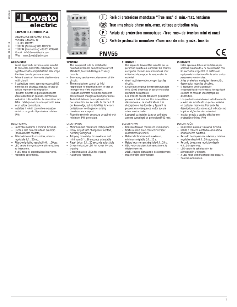
PMV55
ATTENZIONE!
– Questi apparecchi devono essere installati
da personale qualificato, nel rispetto delle
vigenti normative impiantistiche, allo scopo
di evitare danni a persone o cose.
– Prima di qualsiasi intervento disalimentare
tutti i circuiti.
– Il costruttore non si assume responsabilità
in merito alla sicurezza elettrica in caso di
utilizzo improprio del dispositivo.
– I prodotti descritti in questo documento
sono suscettibili in qualsiasi momento di
evoluzioni o di modifiche. Le descrizioni ed i
dati a catalogo non possono pertanto avere
alcun valore contrattuale.
– Installare il relè in contenitore o quadro
elettrico con grado di protezione minimo
IP40.
WARNING!
– This equipment is to be installed by
qualified personnel, complying to current
standards, to avoid damages or safety
hazards.
– Before any service work, disconnect all the
circuits.
– The manufacturer cannot be held
responsible for electrical safety in case of
improper use of the equipment.
– Products illustrated herein are subject to
alteration and changes without prior notice.
Technical data and descriptions in the
documentation are accurate, to the best of
our knowledge, but no liabilities for errors,
omissions or contingencies arising
therefrom are accepted.
– Place the device in enclosure or cabinet with
minimum IP40 protection.
ATTENTION !
– Ces appareils doivent être installés par un
personnel qualifié en respectant les normes
en vigueur relatives aux installations pour
éviter tout risque pour le personnel et le
matériel.
– Avant tout intervention, couper tous les
circuits.
– Le fabricant ne peut être tenu responsable
de la sûreté électrique en cas de mauvaise
utilisation de l'appareil.
– Les produits décrits dans cette publication
peuvent à tout moment être susceptibles
d'évolutions ou de modifications. Les
description et les données y figurant ne
peuvent en conséquence revêtir aucune
valeur contractuelle.
– L’appareil va installer dans un coffret ou
armoire avec degré de protection IP40 mini.
¡ATENCION!
– Estos aparatos deben ser instalados por
personal cualificado y de conformidad con
las normativas vigentes en materia de
equipos de instalación a fin de evitar daños
personales o materiales.
– Antes de efectuar cualquier intervención,
desconectar todos les circuitos.
– El fabricante declina cualquier
responsabilidad relacionada a la seguridad
eléctrica en caso de uso impropio del
dispositivo.
– Los productos descritos en este documento
pueden ser modificados o perfeccionados
en cualquier momento. Por tanto, las
descripciones y los datos aquí indicados no
implican algún vínculo contractual.
– Instalar en caja o cuadro eléctrico con
protección mínimo IP40.
DESCRIZIONE
– Controllo massima e minima tensione.
– Uscita a relè con contatto in scambio
(normalmente eccitato).
– Ritardo intervento massima, minima
regolabile 0,1...20sec.
– Ritardo ripristino regolabile 0,1...20sec.
– LED verde di segnalazione alimentazione
ed intervento.
– 2 LED rossi di segnalazione intervento.
– Ripristino automatico.
DESCRIPTION
– Minimum and maximum voltage control
– Relay output with changeover contact,
normally energised
– Tripping time delay for maximum and
minimum 0.1...20 seconds adjustable
– Reset delay: 0.1...20 seconds adjustable
– Green indication LED for power ON and
tripping
– 2 red indication LEDs for tripping
– Automatic resetting.
DESCRIPTION
– Contrôle tension maximum et minimum.
– Sortie à relais avec contact inverseur
(normalement excité).
– Retard déclenchement maximum,
minimum réglable 0.1...20 s.
– Retard réarmement réglable 0.1...20 s.
– DEL verte signalant l’alimentation et le
déclenchement.
– 2 DEL rouges signalant le déclenchement.
– Réarmement automatique.
DESCRIPCIÓN
– Control de mínima y máxima tensión.
– Salida a relé con contacto conmutado,
normalmente excitado.
– Retardo de disparo de máxima y mínima
regulable desde 0.1...20 segundos.
– Retardo de rearme regulable desde
0.1...20 segundos.
– LED verde de señalización de
alimentación y disparo.
– 2 LED rojos de señalización de disparo.
– Rearme automático.
1
31100038
I164 I GB F E 02 14
1
2
3
4
5
6
FUNZIONAMENTO
Impostare tramite l’apposito commutatore
[5] la tensione nominale da controllare. La
tensione è applicata ai morsetti A1-A2 e
fornisce anche l’alimentazione
all’apparecchio.
L’unità interviene per tensione fuori dai limiti
MAX e MIN.
OPERATION
Set the rated voltage to control, using the
rotating selector [5].
The power supply is connected to terminals
A1-A2, which also power the voltage relay.
The unit trips for value out the MIN and MAX
limits.
FONCTIONNEMENT
A l’aide du commutateur approprié [5], il faut
définir la tension assignée à contrôler. Celleci est appliquée aux bornes A1-A2 et
alimente aussi l’appareil.
L’unité se déclenche quand la tension ne
respecte pas les limites MINI et MAXI.
FUNCIONAMIENTO
Introducir la proporción de tensión a
controlar, usando el selector rotativo [5].
La tensión que se aplica a los terminales
A1-A2, alimenta también al aparato.
La unidad dispara por valor de la tensión
fuera de los límites MIN y MAX establecidos.
NORMALE FUNZIONAMENTO
Quando la tensione A1-A2 rientra nelle soglie
di MAX e MIN impostate, il LED verde “ON” è
acceso fisso, i LED rossi spenti ed il relè di
uscita è eccitato.
NORMAL OPERATION
When the A1-A2 voltage value is within the
programmed MIN and MAX limits, the green
“ON” LED is constantly lighted up, the red
LEDs are off and the output relay is
energised.
FONCTIONNEMENT NORMAL
Quand la tension A1-A2 respecte les seuils
MINI et MAXI programmés, la DEL verte
“ON” est allumée fixe, les DEL rouges sont
éteintes et le relais de sortie est excité.
FUNCIONAMIENTO NORMAL
Cuando el valor de la tensión en A1-A2 está
dentro de los límites programados MIN y
MAX , El LED verde “ON” está
constantemente encendido, el LED rojo está
apagado y el relé energizado.
INTERVENTO PER SUPERAMENTO SOGLIA
MAX O MIN TENSIONE
Quando la tensione è fuori dai limiti di
MAX tensione, impostata tramite il
potenziometro [1], o di MIN tensione,
impostata mediante il potenziometro [3], il
corrispettivo LED rosso lampeggia.
Al termine del relativo tempo di ritardo
impostato tramite i potenziometri [2] e [4], il
relè si diseccita, il LED rosso resta acceso
fisso, mentre il LED verde “ON” lampeggia.
Il ripristino avviene automaticamente,
quando il valore della tensione rientra nel
limite del valore impostato, dopo il ritardo di
reset impostato tramite il potenziometro [6].
Quando la tensione è inferiore a 0,7di Ue
impostata, il relè di uscita si diseccita ed il
LED verde “ON” lampeggia.
OUT OF MAX OR MIN VOLTAGE LIMIT
TRIPPING
When the voltage exceeds either the MAX
voltage limit, regulated by potentiometer [1],
or the MIN voltage limit, regulated by
potentiometer [3], the relative red LED
begins flashing.
When the time delay, adjusted by
potentiometers [2] and [4], lapses, the
output relay de-energises, the red LED
remains constantly switched on while the
green “ON” LED begins flashing.
Resetting is automatic when the voltage
value returns within the limit value, set with
potentiometer [6], after the reset delay
lapses.
When the voltage drops below the 0.7 of the
rated voltage Ue value, the green “ON” LED
flashes and the output relay
de-energises.
DÉCLENCHEMENT POUR DÉPASSEMENT
DU SEUIL DE TENSION MAXI OU MINI
Quand la tension dépasse les limites de
tension MAXI, programmée à l’aide du
potentiomètre [1], ou de tension MINI,
programmée à l’aide du potentiomètre [3], la
DEL rouge correspondante clignote.
Au terme du temps de retard relatif
programmé à l’aide des potentiomètres [2]
et [4], le relais se désexcite, la DEL rouge
reste allumée fixe tandis que la DEL verte
“ON” clignote.
Le réarmement se produit automatiquement
quand la valeur de la tension respecte la
limite programmée, après le retard de
réarmement programmé à l’aide du
potentiomètre [6]. Quand la tension est
inférieure à 0,7 de Ue programmée, le relais
de sortie se désexcite et la DEL verte “ON”
clignote.
DISPARO POR SUPERACIÓN DEL UMBRAL
DE MIN Y MAX TENSIÓN.
Cuando el voltaje excede, tanto el límite MAX
regulado con el potenciómetro [1], como el
MIN regulado con el potenciómetro [3], El
LED rojo correspondiente comienza a
parpadear.
Cuando el tiempo de retardo, ajustado con el
potenciómetro [2] y [4], transcurre, el relé
de salida se des-excita, el LED rojo
permanece constantemente encendido
mientras el LED verde ON parpadea.
El rearme es automático cuando la tensión
retorna a un valor entre los límites
establecidos, después del valor de retardo
establecido mediante el potenciómetro [6],
Cuando la tensión cae por debajo del 0.7 del
valor de Ue establecida, el LED verde ON
parpadea y el relé de salida se des-excita.
2
31100038
WIRING DIAGRAM
SCHEMA DE CONNEXION
ESQUEMA DE CONEXIÓN
DIAGRAMMA DI FUNZIONAMENTO
OPERATIONAL DIAGRAM
DIAGRAMME DE FONCTIONNEMENT
DIAGRAMA DE FUNCIONAMIENTO
I164 I GB F E 02 14
SCHEMA DI COLLEGAMENTO
Massima e minima tensione
Maximum and Minimum voltage
Tension maximum et minimum
Máxima y Mínima tensión
Reset time
at powen on
MAX Delay
Reset delay
MIN Delay
Reset delay
Set up V MAX
Hysteresis
Hysteresis
Set up V MIN
V MAX
V MIN
ON
Relay
14
11
12
A1 - A2
ATTENZIONE!
Apparecchio con ripristino automatico
CAUTION!
Device with automatic resetting
ATTENTION!
Appareil avec réarmement automatique
ATENCION!
Aparato con rearme automático
DIMENSIONI MECCANICHE [mm]
MECHANICAL DIMENSIONS [mm]
DIMENSIONS MECANIQUES [mm]
DIMENSIONES MECÁNICAS [mm]
43.7
45.0
90.0
98.3
104.7
Ø4.2
5
35.8
58
59.9
3
4
ISOLATION
Operating range
Power consumption
Power dissipation
Type of resetting
Resetting time at power on
ADJUSTMENTS
Tripping for MAX voltage
Tripping for MIN voltage
Hysteresis respect to adjusted MIN
and MAX values
Tripping delay for MAX and MIN
Reset delay
OUTPUT RELAY
Number of outputs
Type of output
Rated voltage
Maximum switching voltage
IEC/EN 60947-5-1 designation
Electrical life
Mechanical life
INSULATION
Rated impulse withstand voltage Uimp
Power frequency withstand voltage
Rated insulation voltage Ui
AMBIENT CONDITIONS
Operating temperature
Storage temperature
Relative humidity
Maximum pollution degree
CONNECTIONS
Type of terminals
Cable cross section
Tightening torque
HOUSING
Version
Material
Mounting / Fixing
Degree of protection
Weight
CERTIFICATIONS AND COMPLIANCE
Certifications
Limiti di funzionamento
Potenza assorbita
Potenza dissipata
Tipo di ripristino
Tempo di ripristino all’alimentazione
IMPOSTAZIONI
Intervento di MAX tensione
Intervento di MIN tensione
Isteresi rispetto al valore di MIN e MAX
impostato
Ritardo intervento per MAX e MIN
Ritardo ripristino
RELÈ DI USCITA
Numero di uscite
Tipo di uscita
Tensione nominale
Tensione max d’interruzione
Designazione secondo IEC/EN 60947-5-1
Durata elettrica
Durata meccanica
ISOLAMENTO
Tensione nom. di tenuta a impulso Uimp
Tensione di tenuta a frequenza d’esercizio
Tensione nominale d’isolamento Ui
CONDIZIONI AMBIENTALI
Temperatura d’impiego
Temperatura di stoccaggio
Umidità relativa
Grado di inquinamento massimo
CONNESSIONI
Tipo di terminali
Sezione conduttori
Coppia di serraggio
CONTENITORE
Esecuzione
Materiale
Montaggio
Grado di protezione
Peso
OMOLOGAZIONI E CONFORMITÀ
Omologazioni
Conformi alle norme
UL Marking
Durée de vie mécanique
Rated frequency
Frequenza nominale
Temperatura de almacenaje
Humedad relativa
Polución MAX
CONEXIONES
Tipo de terminales
Sección de cable
Humidité relative
Degré de pollution maximum
CONNEXIONS
Type de bornes
Section des conducteurs
Compliant with standards
Conformes aux normes
Use 60°C/75°C copper (CU) conductor and wire size range 18-12 AWG, stranded or solid
Certifications
CERTIFICATIONS ET CONFORMITE
Masse
Degré de protection
Montage
Matière
Type
BOITIER
Conforme a normas
Homologaciones
HOMOLOGACIONES Y CONFORMIDAD
Peso
Grado de protección
Montaje
Material
Ejecución
CONTENEDOR
Par de apriete
Temperatura de empleo
Température de stockage
Couple de serrage
CONDICIONES AMBIENTALES
Température de fonctionnement
Tensión nominal de aislamiento Ui
Tensión soportada a frecuencia industrial
Tensión nom. soportada de impulso Uimp
AISLAMIENTO
Endurancia mecánica
Endurancia eléctrica
Conforme a IEC/EN 60947-5-1
Tensión MAX de interrupción
Tensión MAX.
Tipo de salida
Numero de relés
RELÉ DE SALIDA
Retardo rearme
Retardo disparo por MAX. y MIN:
Histéresis respecto a los valores de
MAX y MIN introducidos
Disparo de Mínima tensión
Disparo de Máxima tensión
AJUSTES
Tiempo de rearme de la alimentación
Rearme
Potencia disipada
Potencia absorbida
Limite de funcionamiento
Frecuencia nominal
Tensión nominal Ue
ENVIRONNEMENT
Tension assignée d’isolement Ui
Tension de tenue à fréquence de service
Tension assignée de tenue aux chocs
Durée de vie électrique
Désignation selon IEC/EN 60947-5-1
Tension maxi coupure
Tension assignée
Type de sortie
Nombre de relais
RELAIS DE SORTIE
Retard réarmement
Retard déclenchement pour MAXI et MINI
Hystérésis par rapport à la valeur
MINI et MAXI programmée
Déclenchement de tension MINI
Déclenchement de tension MAXI
REGLAGES
Temps réarmement mise en tension
Type de réarmement
Dissipation
Consommation
Limites de fonctionnement
Fréquence assignée
Tension assignée Ue
Rated voltage Ue
Tensione nominale Ue
CIRCUITO DE ALIMENTACIÓN Y CONTROL
CIRCUIT D’ALIMENTATION ET DE
COMMANDE
CONTROL AND POWER SUPPLY CIRCUIT
CIRCUITO DI ALIMENTAZIONE
E CONTROLLO
CARACTERISTICAS TECNICAS
CARACTERISTIQUES TECHNIQUES
TECHNICAL CHARACTERISTICS
CARATTERISTICHE TECNICHE
Fixe
cULus, GOST
130g
IP40 face avant
IP20 en terminales
Guía DIN 35mm (IEC/EN60715) o
tornillo utilizando clip extraible
35mm DIN rail (IEC/EN60715) or
by screws using extractible clips
IP40 on front
IP20 on terminals
Polyamide
Polyamide
2 modules (DIN 43880)
0.8Nm (7lbin)
0.2 - 4.0 mm2 (24 - 12 AWG)
2 modules (DIN 43880)
Fixed
3
<90%
-30...+80°C
-20...+60°C
440VAC
4kV
6kV
30x106 ops
105 ops
1 contact inverseur
AC1 8A-250VAC / B300
400VAC
250VAC
1
0.1...20sec
0.1...20sec
3%
80...95% [%Ue]
Automatique
31100038
IP40 frontal
IP20 connexions
Profilè 35mm (IEC/EN60715)
ou à vis par clips extractibles
Poliamida
2 módulos (DIN 43880)
Fijo
30x106 ops
105 ops
1 contacto commutado
Automático
IEC/EN 60255-6, IEC/EN 60255-5, IEC/EN 61010-1 IEC/EN 61000-6-2, IEC/EN 61000-6-3, IEC/EN 60068-2-6,
IEC/EN 60068-2-27, IEC/EN 60028-2-61, DIN 43880, UL 508, CSA C22.2 N°14-95
IP40 sul fronte
IP20 connessioni
Guida 35mm (IEC/EN60715)
oppure a vite a mezzo clip estraibili
Poliammide
2 moduli (DIN 43880)
Fissi
105 ops
30x106 ops
105 operazioni
500ms
1.5W max
105...115% [%Ue]
1 changeover contact
Automatic
30x106 operazioni
1 contatto in scambio
Automatico
220...240VAC: 10VA max
380...415VAC: 17VA max
0.7...1.2Ue
50/60Hz ±5%
208...240VAC - 380...440VAC
I164 I GB F E 02 14

