Bulletin 817 / Installation instructions
Attention: To prevent electrical shock, disconnect from power source
before installing or servicing.
Bulletin 817-E.
Bulletin 817 / Montageanleitung
Achtung: Vor Installations- oder Servicearbeiten Stromversorgung
unterbrechen, um Unfälle zu vermeiden.
Bulletin 817 / Instructions de montage
Attention: Avent le montage et la mise en service, couper l'alimentation secteur
pour éviter toutes décharges.
Bulletin 817 / Istruzioni per il montaggio
Attenzione: Per prevenire infortuni, togliere tensione prima dell'installazione
o manutenzione.
Bulletin 817 / Instrucciones de montaje
Atencion: Desconéctese de la corriente eléctrica, antes de la instalación o
del servicio, a fin servicio, a fin de impedir sacudidas eléctricas.
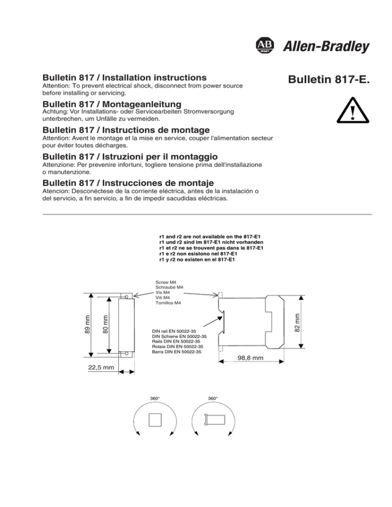
r1 and r2 are not available on the 817-E1
r1 und r2 sind im 817-E1 nicht vorhanden
r1 et r2 ne se trouvent pas dans le 817-E1
r1 e r2 non esistono nel 817-E1
r1 y r2 no existen en el 817-E1
82 mm
80 mm
89 mm
Screw M4
Schraube M4
Vis M4
Viti M4
Tornillos M4
DIN rail EN 50022-35
DIN Schiene EN 50022-35
Rails DIN EN 50022-35
Rotaia DIN EN 50022-35
Barra DIN EN 50022-35
98,8 mm
22,5 mm
360°
360°
Terminal and block circuit diagram of Bulletin 817
Anschlussplan und Blockschaltbild Bulletin 817
Plan de raccordement et schéma bloc du Bulletin 817
Schema di raccordo e schema elettrico a blocchi Bulletin 817
Plano de conexiones y esquema de conexiones de blocque Bulletin 817
1) green
grün
vert
verde
verde
Us
A1
T1
PTC
T2
r1
r2
A2
2) red
rot
rouge
rosso
rojo
Relay Output
Power on
+ Overtemperature
+ Open Circuit
+ Short Circuit
LED Indication
1)
2)
2)
2)
Remote reset*
or automatic Reset
Test / Reset
button
Power off
(*Only for 817-E2)
817-E1
817-E2
(Only for 817-E2)
13
An application example
Starter K1 and F1
with additional
Bulletin 817
Applikationsbeispiel
Starter K1 und F1 mit
zusätzlichem Bulletin 817
Exempled’application
Starter K1 et F1 avec
Bulletin 817
supplémentaire
F7
L1
L1
Ejemplode aplicación
Arrancador K1 y F1 con
Bulletin 817adicional
22
N
13
PE
S1
S2
r1
K1
A1
1
3
5
A2
2
4
6
F1
F2 Bulletin 817-E.
M
∼
+t°
M1 3
Legend
K1 Contactor
F1 Thermal overload
relay
F2 Thermistor protection
relay Bulletin 817
S1 ON button
S0 OFF button
S2 Remote reset button
Us Supply voltage
H1 Signal lamp
"Contactor ON"
H2 Signal lamp
Bulletin 817
"tripped"
B1 Thermistor in
protected object
F1
T2
r2
14
13
21
A1
14
22
A2
97
95
98
96
A1
K1
B1
T1
Legende
K1 Schütz
F1 Thermorelais
F2 ThermistorSchutzrelais
Bulletin 817
S1 EIN- Taste
S0 AUS-Taste
S2 Fernrückstell-Taste
Us Steuerspannung
H1 Signallampe
"Schütz EIN"
H2 Signallampe
Bulletin 817
"ausgelöst"
B1 Thermistor in
geschütztem Motor
T2
B1
H2
PTC
H1
A2
(L2/F8)
N
Légende
K1 Contacteur
F1 Relais thermique
F2 Relais de protection
à thermistor
Bulletin 817
S1 Touche "EN"
S0 Touche "HORS"
S2 Touche de
réarmement à
distance
Us Tension de
commande
H1 Voyant
"Contacteur EN"
H2 Voyant Bulletin 817
"déclenché"
B1 Thermistor dans le
moteur protégé
For automatic reset with 817-E2 connect r1-r2
Für automatische Rückstellung mit 817-E2 r1-r2 verbinden
Relier r1 et r2 pour le réarmement automatique avec le 817-E2
Changes reserved
22.253.902-01 / 09. 2003
Edition 3
2
14
13
K1
F2 Bulletin 817-E.
T1
2
Esempio d’applicazione
Starter K1 e F1 con
Bulletin 817
supplementare
22
AC Us
S0
L3
2
21
21
L2
2
14
2
2
Leggenda
K1 Contattore
F1 Termorelè
F2 Relè di protezione a
thermistor Bulletin 817
S1 Tasto INSERIMENTO
S0 Tasto
DISINSERIMENTO
S2 Tasto di azzeramento
a distanza
Us Sovratensione
H1 Spia luminosa
"Contattore
INSERITO"
H2 Spia luminosa
Bulletin 817
"attivato"
B1 Thermistor nel
motore protetto
Leyenda
K1 Contactor
F1 Relé térmico
F2 Relé de protección por
termistores Bulletin 817
S1 Tecla CERRAR
S0 Tecla ABRIR
S2 Tecla de reposición a
distancia
Us Tensión de mando
H1 Lámpara de
señalización
"Contactor
CERRADO"
H2 Lámpara de
señalización
Bulletin 817
"apagada"
B1 Thermistor en motor
protegido
Per l’azzeramento automatico, collegare con 817-E2 r1-r2
Para la reposición automática con 817-E2 conectar r1-r2

