JUNG PUMPEN MODUL SICHERHEITSBARRIERE ± 24V
Technische Daten
• Eingangsspannung: max. ±24 V
• Strom: max. 50 mA
• Interne Sicherung: 50 mA mittelträge
• Durchgangswiderstand: 360 ±7,5 Ω
• Anschlussklemmen: 2,5 mm²
• PA-Anschlussklemmen: 4,0 mm²
• Temperaturbereich: -20 bis 50°C
• Luftfeuchtigkeit: 0-90% rH, nicht kondensierend
• Eigensichere Daten:
• Ex-Zulasssung: Ex II (2) G [ Ex ia ] IIC/IIB
• Um : 253 V~
• Uo : 30,5 V
• Io
: 90 mA
• Po : 684 mW
• Max. zulässige äußere Induktivität, Kapazität:
• Lo für IIC/IIB : 43 µH / 200 µH
• Co für IIC/IIB : 63 nF / 510 nF
Beschreibung
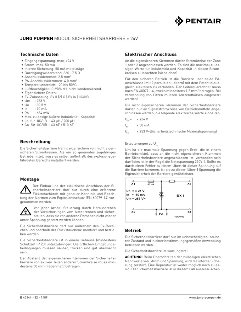
Die Sicherheitsbarriere trennt eigensichere von nicht eigensicheren Stromkreisen. Als ein so genanntes zugehöriges
Betriebsmittel, muss es selber außerhalb des explosionsgefährdeten Bereichs installiert werden.
Montage
Elektrischer Anschluss
An die eigensicheren Klemmen dürfen Stromkreise der Zone
1 oder 2 angeschlossen werden. Es sind die maximal zulässigen Werte für Induktivität und Kapazität in diesen Stromkreisen zu beachten (siehe oben).
Für den sicheren Betrieb ist die Barriere über beide PAAnschlüsse (mit 2 parallelen Leitern) mit dem Potentialausgleich elektrisch zu verbinden. Der Leiterquerschnitt muss
nach EN 60079-14 jeweils mindestens 1,5 mm² betragen. Bei
Verwendung von Litzen müssen Aderendhülsen eingesetzt
werden!
Die nicht eigensicheren Klemmen der Sicherheitsbarriere
dürfen nur an Signalstromkreise von Betriebsmitteln angeschlossen werden, die folgende elektrische Werte einhalten:
UN =
≤ ±24 V
IN
≤ 50 mA
Um
≤ 253 V~(Sicherheitstechnische Maximalspannung)
Erläuterungen zu Um
Um ist die maximale Spannung gegen Erde, die in einem
Betriebsmittel, dass an die nicht eigensicheren Klemmen
der Sicherheitsbarriere angeschlossen ist, vorhanden sein
darf (dies ist in der Regel die Netzspannung 230V~). Sollte es
durch einen Fehler zu einem Übertritt dieser Spannung auf
die Barriere kommen, ist bis zu dieser (Über-) Spannung die
Eigensicherheit der Barriere gewährleistet.
Der Einbau und der elektrische Anschluss der Sicherheitsbarriere darf nur durch eine erfahrene
Elektrofachkraft mit genauer Kenntnis und Beachtung der Normen zum Explosionsschutz (EN 60079-14) vorgenommen werden.
Vor jeder Arbeit: Steuerung durch Herausdrehen
der Vorsicherungen vom Netz trennen und sicherstellen, dass sie von anderen Personen nicht wieder
unter Spannung gesetzt werden können.
Die Sicherheitsbarriere darf nur außerhalb des Ex-Bereiches und oberhalb der Rückstauebene montiert und betrieben werden.
Die Sicherheitsbarriere ist in einem Gehäuse (mindestens
Schutzart IP 20) unterzubringen. Die örtlichen Umgebungsbedingungen müssen sauber, trocken und gut überwacht
sein.
Der Abstand der eigensicheren Klemmen der Sicherheitsbarriere von aktiven Teilen anderer Stromkreise muss mindestens 50 mm (Fadenmaß) betragen.
B 40144 - 32 - 1409
Betrieb
Die Sicherheitsbarriere darf nur im unbeschädigten, sauberen Zustand und in einer bestimmungsgemäßen Anwendung
betrieben werden.
Die Sicherheitsbarriere ist wartungsfrei.
ACHTUNG! Beim Überschreiten der zulässigen elektrischen
Nennwerte von Strom und Spannung, wird die interne Sicherung zerstört. Eine Reparatur ist weder möglich noch zulässig. Die Sicherheitsbarriere ist in diesem Fall auszutauschen.
www.jung-pumpen.de
JUNG PUMPEN MODULE SAFETY BARRIER ± 24V
Technical data
• Input voltage: max. ±24 V
• Current: max. 50 mA
• Internal fuse: 50 mA semi-delay
• Volume resistivity: 360 ±7.5 Ω
• Connection terminals: 2.5 mm²
• PEQ connection terminals: 4.0 mm²
• Temperature range: -20°C to +50°C
• Humidity: 0 to 90 % RH, with no condensation
• Intrinsic safety data:
• Ex-zone approval: Ex II (2) G [ Ex ia ] IIC/IIB
• Um : 253 V~
• Uo : 30.5 V
• Io
: 90 mA
• Po : 684 mW
• Max. permissible external inductance, capacitance:
• Lo for IIC/IIB : 43 µH / 200 µH
• Co for IIC/IIB : 63 nF / 510 nF
Description
The safety barrier separates intrinsically safe circuits from
circuits that are not intrinsically safe. As an item of so-called
accessory operating equipment, the barrier itself must be
installed outside the potentially explosive zone.
Electrical connection
Zone 1 and Zone 2 electrical circuits may be connected to the
intrinsically safe terminals. The maximum permissible values for inductance and capacitance in these electric circuits
must be observed (see above).
To ensure safe operation, the barrier must be connected to
the potential equalisation via both of the PEQ connections
(with two parallel conductors). The cross-sectional area of
the conductor in each case must be at least 1.5 mm², in accordance with EN 60079-14. If stranded cables are used,
these must be fitted with cable end-sleeves.
Those terminals of the safety barrier that are not intrinsically
safe may be connected only to signal circuits of operating
equipment complying with the following values:
UN =
≤ ±24 V
IN
≤ 50 mA
Um
≤ 253 V~ (maximum safe voltage)
Um explained
Um is the maximum voltage to earth that is permitted in any
operating equipment connected to the safety barrier terminals that are not intrinsically safe (this is usually the mains
voltage: 230V~). Should this voltage across the barrier be exceeded due to a malfunction, the intrinsic safety of the barrier is guaranteed up to this (excess) voltage.
Installation
The installation and electrical connection of the
safety barrier may be carried out only by an experienced, qualified electrician with a precise understanding of the explosion protection standards (EN 60079,
Part 14) and in complete compliance with these standards.
Before carrying out any works: disconnect the pump
and the controls from the mains and take steps to
ensure that it cannot be emergized again.
The safety barrier may only be installed and operated outside
the potentially explosive area and above the back-flow level.
The safety barrier must be installed in a housing unit (with a
minimum protection category of IP 20). The device must be
kept in a clean, dry and well monitored environment.
The distance between the intrinsically safe terminals of the
safety barrier and the active parts of any other electrical circuits must be at least 50 mm (string length).
2
Operation
The safety barrier may only be used for its intended purpose
and only when in an undamaged and clean condition.
The safety barrier is maintenance-free.
ATTENTION! If the permissible electrical ratings for current
and voltage are exceeded, the internal fuse will be irreparably damaged. It is neither possible nor permissible to repair
this fuse. If the fuse is damaged, the safety barrier must be
replaced.
JUNG PUMPEN MODULO BARRIERA DI SICUREZZA ± 24V
Dati tecnici
• Tensione in ingresso: max. ±24 V
• Corrente: max. 50 mA
• Fusibile interno: 50 mA medianamente inerte
• Resistenza di contatto: 360 ±7,5 Ω
• Morsetti di collegamento: 2,5 mm²
• Morsetti di collegamento PA: 4,0 mm²
• Limiti di temperatura: da -20 a 50°C
• Umidità: 0-90% rH, non condensante
• Dati a sicurezza intrinseca:
• Certificazione Ex: Ex II (2) G [ Ex ia ] IIC/IIB
• Um : 253 V~
• Uo : 30,5 V
• Io
: 90 mA
• Po : 684 mW
• Induttività esterna max. consentita, capacità:
• Lo per IIC/IIB : 43 µH / 200 µH
• Co per IIC/IIB : 63 nF / 510 nF
Descrizione
La barriera di sicurezza separa i circuiti di corrente a sicurezza intrinseca e quelli non a sicurezza intrinseca. Quindi
un corrispondente mezzo d’esercizio deve essere installato
all’esterno dell’area a pericolo d’esplosione.
Collegamento elettrico
Ai morsetti a sicurezza intrinseca è possibile collegare circuiti elettrici della zona 1 o 2. Si devono rispettare i valori
massimi consentiti di induttività e capacità in questi circuiti
elettrici (vedere sopra).
Per il funzionamento sicuro la barriera deve essere collegata elettricamente mediante i due collegamenti PA (con 2
conduttori paralleli) con compensazione di potenziale. La
sezione del conduttore deve ammontare ad almeno 1,5 mm²
secondo la norma EN 60079-14. In caso di uso di trefoli si
devono impiegare boccole aderenti!
I morsetti non a sicurezza intrinseca della barriera di sicurezza possono essere collegati ai circuiti elettrici di segnalazione dei mezzi d’esercizio che rispettano i seguenti valori
elettrici:
UN =
≤ ±24 V
IN
≤ 50 mA
Um
≤ 253 V~ (tensione massima per sicurezza tecnica)
Spiegazioni relative a Um
Um è la tensione massima da terra che può essere presente
per un mezzo d’esercizio collegato a morsetti non a sicurezza intrinseca della barriera di sicurezza (solitamente si
tratta di tensione di rete a 230V~). Se a causa di un errore
si verifica un passaggio di questa tensione alla barriera, si
deve garantire la sicurezza intrinseca della barriera fino a
questa tensione.
Montaggio
L’installazione e il collegamento elettrico della barriera di sicurezza può essere eseguita solo da un
elettricista esperto con conoscenze precise e il rispetto delle norme per la protezione antideflagrante (EN
60079-14)
Prima di qualsiasi operazione: staccare la pompa e
la centralina dall'alimentazione in modo che non
possano essere rimesse in collegamento da altre
persone.
La barriera di sicurezza può essere montata e messa in funzione solo all’esterno della zona Ex e al di sopra del livello
di ristagno.
La barriera di sicurezza è installata in un alloggiamento
(classe di protezione minima IP 20). Le condizioni ambientali
locali devono essere pulite, asciutte e ben controllate.
La distanza dei morsetti a sicurezza intrinseca della barriera
di sicurezza dalle parti attive di altri circuiti deve essere di
almeno 50 mm (misura del filo).
Funzionamento
La barriera di sicurezza può essere azionata solo in stato
pulito, non danneggiato e in un’applicazione conforme alle
disposizioni.
La barriera di sicurezza non necessita di manutenzione.
ATTENZIONE! In caso di superamento dei valori nominali
elettrici consentiti di corrente e tensione, il fusibile interno
viene distrutto. Una riparazione non è né possibile né consentita. In questo caso la barriera di sicurezza deve essere
sostituita.
3
4
5
6
7
DE
CZ
DK
EN
FI
· Konformitätserklärung
· Prohlášeni o shodě
· Overensstemmelseserklæring
· Declaration of Conformity
· Vaatimustenmukaisuusvakuutus
FR
HU
IT
NL
PL
DE · Richtlinien - Harmonisierte Normen
CZ · Směrnice - Harmonizované normy
DK · Direktiv - Harmoniseret standard
EN · Directives - Harmonised standards
FI · Direktiivi - Yhdenmukaistettu standardi
• 94/9 EG
(ATEX)
• 2004/108 EG (EMC)
· Déclaration de Conformité
· Megfelelöségi nyilatkozat
· Dichiarazione di conformità
· Conformiteitsverklaring
· Deklaracja zgodności
FR · Directives - Normes harmonisées
HU · Irányelve - Harmonizá szabványok
IT · Direttive - Norme armonizzate
NL · Richtlijnen - Geharmoniseerde normen
PL · Dyrektywy - Normy zharmonizowane
RO · Declaraţie de conformitate
SE · Försäkran om överensstämmelse
SK · Vyhlásenie o zhode
RO · Directivă - Norme coroborate
SE · Direktiv - Harmoniserade normer
SK · Smernice - Harmonizované normy
EN 60079-0:2006, EN 60079-11:2007
EN 61000-6-2:2005, EN 61000-6-3:2007
JUNG PUMPEN GmbH - Industriestr. 4-6 - 33803 Steinhagen - Germany - www.jung-pumpen.de
DE · Wir erklären in alleiniger Verantwortung, dass das Produkt den aufgeführten Richtlinien entspricht.
CZ · Prohlašujeme na svou výlučnou odpovědnost, že výrobek odpovídá jmenovaným směrnicím.
DK · Vi erklærer under ansvar at produktet i overensstemmelse med de retningslinjer
EN · We hereby declare, under our sole responsibility, that the product is in accordance with the specified Directives.
FI · Me vakuutamme omalla vastuullamme, että tuote täyttää ohjeita.
FR · Nous déclarons sous notre propre responsabilité que le produit répond aux directives.
HU · Kizárólagos felelősségünk tudatában kijelentjük, hogy ez a termék megfelel az Európai Unió fentnevezett irányelveinek.
IT · Noi dichiariamo sotto la nostra esclusiva responsabilità che il prodotto è conforme alle direttive citate
NL · Wij verklaren geheel onder eigen verantwoordelijkheid dat het product voldoet aan de gestelde richtlijnen.
PL · Z pełną odpowiedzialnością oświadczamy, że produkt odpowiada postanowieniom wymienionych dyrektyw.
RO · Declarăm pe proprie răspundere că produsul corespunde normelor prevăzute de directivele mai sus menţionate.
SE · Vi försäkrar att produkten på vårt ansvar är utförd enligt gällande riktlinjer.
SK · Na výlučnú zodpovednosť vyhlasujeme, že výrobok spíňa požiadavky uvedených smerníc.
Sicherheitsbarriere ± 24 V
0044
(JP40140)
II (2) G [Ex ia] IIC/ IIB
TÜV 06 ATEX 552823
Steinhagen, 05-05-2014
TÜV NORD CERT GmbH, Langemarckstr. 20, 45141 Essen, Germany
______________________
Stefan Sirges, General Manager
CE 121-14-1405
ppa. ____________________
Frank Erdt, Sales Director

