ISTRUZIONI PER PT30 – PT40
Cronotermostati elettromeccanici a pile
INSTRUCTIONS FOR PT30 – PT40
Battery-operated electromechanical time thermostats
1 – CARATTERISTICHE TECNICHE
1 – TECHNICAL SPECIFICATIONS
1 – CARACTERISTIQUES TECHNIQUES
1 – TECHNISCHE EIGENSCHAFTEN
1 – CARACTERISTICAS TECNICAS
- Termostato unipolare a montaggio indipendente
non elettronico, funzionante a tensione di vapore.
- Regolazione della temperatura da +5°C a +30°C.
- Differenziale ∆t≤1K.
- Orologio al quarzo per programmazione:
- giornaliera per PT30
- settimanale per PT40
- Alimentazione mediante una pila 1,5 V tipo LR 6
alcalina (non fornita con l’apparecchio)
- Commutatore elettrico a 3 posizioni:
- POSIZ.CENTRALE - ☼
- Contatti elettrici 6(1,5) A/250V~
- Tensione impulsiva nominale: 4kV
- Dispositivo di classe I
- Grado di protezione: IP20
- Azioni di tipo 1BU
- Situazione di inquinamento del dispositivo: grado
di polluzione 2
- Free mounted non-electric single-pole thermostat,
functioning by vapour pressure.
- Temperature adjustments from +5°C to +30°C.
- Differential ∆t≤1K.
- Quartz clock for programming:
- daily for PT30
- weekly for PT40
- Powered by 1,5 V LR 6 alkaline battery (not
supplied)
- 3 position electrical switch:
- CENTRAL POS. - ☼
- Electrical contacts 6(1,5) A/250V~
- Rated pulsating voltage: 4kV
- Protection against shock: I
- Degree of protection: IP20
- Type of action: 1BU
- Pollution level of the device: degree of pollution 2
- Thermostat unipolaire à montage indépendant non
électronique, fonctionnant à tension de vapeur.
- Régulation de la température de +5°C à +30°C.
- Différentiel ∆t≤1K.
- Horloge à quartz pour programmation:
- journalière pour PT30
- hebdomadaire pour PT40
- Alimentation au moyen d’une pile d’1,5 V type LR
6 alcaline (non fournie avec l’appareil).
- Commutateur électrique à 3 positions:
- POS.CENTR. – ☼
- Contacts électriques 6(1,5) A/250V~
- Tension d’impulsion nominale: 4kV
- Dispositif de classe I
- Degré de protection: IP20
- Actions de type 1BU
- Situation de pollution du dispositif: degré de
pollution 2
- Nicht elektronisch, separat montiert Vorrichtung,
mit Dampfspannung funktionierend.
- Temperaturregulierung von +5°C bis +30°C.
- Differential ∆t≤1K.
- Quarzuhr für Programmierung:
- täglich PT30
- wöchentlich PT40
- Ladung mit einer 1,5 V Batterie, Typ LR 6
alkalisch PT40 (wird nicht mit dem Gerät geliefert).
- Elektrischer Umschalter mit drei verschiedenen
Positionen:
- ZENTRALE POSITION – ☼
- Elektrokontakte 6(1,5) A/250V~
- Nennstossspannung: 4kV
- Prüfklasse: I
- Schutzgrad: IP 20
- Schutzklasse: 1BU
- Belastungssituation des Geräts:
Verunreinigungsgrad 2
- Termostato unipolar con montaje independiente
no electrónico, que funciona con tensión de vapor.
- Regulación de la temperatura de +5°C a +30°C.
- Diferencial ∆t≤1K.
- Reloj de cuarzo programación:
- diaria en el PT30
- semanal en el PT40
- Alimentación mediante una pila de 1,5 V tipo LR 6
alcalina (no suministrada con el aparato)
- Conmutador eléctrico de 3 posiciones:
- POSIC.CENTR. – ☼
- Contactos eléctricos 6(1,5) A/250V~
- Tensión de impulso nominal: 4kV
- Dispositivo de clase I
- Grado de protección: IP 20
- Acciones de tipo 1BU
- Situación de contaminación del dispositivo: grado
de polución 2
2 – INSTALLATION
2 – INSTALLAZIONE
Svitare la vite di serraggio del coperchio.
Separare la scatola dallo zoccolo.
Passare i fili attraverso la finestra dello zoccolo
e, utilizzando le due viti in dotazione, fissare lo
zoccolo sulla scatola da incasso (interasse 60
mm) oppure direttamente alla parete (interasse
115 mm).
Collegare i fili elettrici dell’impianto come segue:
- morsetti 1 e 2 per utilizzatori di contatto diretto
(stacca per aumento di temperatura) come
sono generalmente i riscaldatori.
Oppure:
- morsetti 1 e 3 per utilizzatori di contatto
inverso, di commutazione (stacca per riduzione
di temperatura) come sono generalmente i
condizionatori.
IMPORTANTE:
PER
IL
CORRETTO
COLLEGAMENTO ELETTRICO RISPETTARE LE
INDICAZIONI DEL SEGUENTE SCHEMA.
Unscrew the cover retaining screw.
Separate the box from the socket.
Pass the wires through the window in the plinth
and, using the two screws provided, fix the
socket to the flush-mounting box (centre distance
60mm) or directly to the wall (centre distance
115mm).
Connect the electric wires as follows:
- terminals 1 and 2 for users of direct switching
contact (switches off when temperature
increases) as for heaters.
Or:
- terminals 1 and 3 for users of inverse switching
contact (switches off when temperature drops)
as for conditioners.
IMPORTANT FOR CORRECT ELECTRICAL
CONNECTION FOLLOW THE DIAGRAM BELOW.
2 – INSTALLATION
2 – PROCEDIMIENTO DE INSTALACIÓN
Dévisser la vis de serrage du couvercle.
2 – INSTALLATION
Séparer la boîte du socle.
Die Schraube vom Deckel abschrauben.
Passer les fils à travers la fenêtre du culot et en
utilisant les deux vis fournies fixer le socle sur la
boîte a encastrer (entre-axe 60mm) ou bien
directement sur le mur (entre-axe 115mm).
Relier les fils électriques de l’installation en
procédant de la façon suivante:
- bornes 1 et 2 pour utilisateurs de contact direct
(déclenchement en cas de augmentation de
température) comme le sont généralement les
dispositifs de chauffage.
Ou bien:
- bornes 1 et 3 pour utilisateurs de contact
inversé, de commutation (déclenchement en
cas de diminution de température) comme le
sont généralement les climatiseurs.
Das Gehäuse von dem Sockel trennen.
Die Drahte durch das Fenster im Sockel führen
und mit den zwei Schrauben des Zubehörs den
Sockel an dem Gehäuse (Achsenabstand 60mm)
oder direkt an der Wand (Achsenabstand
115mm) befestigen.
die Elektrodrahte wie folgt verbinden:
- Klemme 1 und 2 für Verbraucher mit
Direktkontakt
(schaltet
bei
Temperaturerhöhung ab), wie generell bei Heizgeräte.
Oder:
- Klemme 1 und 3 für Verbraucher mit
Gegenkontakt zur Umschaltung (schaltet bei
Abnehmen der Temperatur ab), wie generell
bei Klimaanlagen.
IMPORTANT: POUR UN BRANCHEMENT
ELECTRIQUE CORRECT, RESPECTER LES
INDICATIONS DU SCHEMA SUIVANT.
WICHTIG: FÜR EINE KORREKTE ELEKTRISCHE
VERBINDUNG, DEN ANWEISUNGEN DES
FOLGENDEN SCHEMAS FOLGEN.
Aflojar el tornillo de fijación de la tapa.
Separar la caja del zócalo.
Pasar los hilos a través de la ventana del zócalo
y, utilizando los dos tornillos suministrados, fijar
el zócalo a la caja por empotrar (distanzia entre
ejes 60mm) o bien directamente a la pared
(distanzia entre ejes 115mm).
Conectar los hilos eléctricos de la manera
siguiente:
- bornes 1 y 2 para emploes de contacto directo
(corta por aumento de temperatura) como son
en general los calefactores.
O bien:
- bornes 1 y 3 para emploes de contacto inverso
(corta por bajada de temperatura) como son en
general los acondicionadores.
IMPORTANTE:
PARA
EFECTUAR
CORECTAMENTE LA CONEXION ELECTRICA
RESPETAR LAS INDICACIONES DEL ESQUEMA
SIGUIENTE.
HEATING
RISCALDAMENTO
CONDIZIONAMENTO
TERMICO
HEIZUNG
THERMAL
CONDITIONING
WARMEKLIMATISIERUNG
CLIMATISATION
THERMIQUE
Innestare tra loro le morsettiere e applicare il
cronotermostato sullo zoccolo.
Fissare il coperchio riavvitando la vite.
Inserire una pila da 1,5V tipo LR 6 nell’apposita
sede, facendo attenzione alla polarità (si
consiglia di sostituire la pila una volta all’anno
anche se non risulta esaurita).
CHAUFFAGE
Mettere all’ora l’orologio, programmare ed
eseguire le regolazioni come indicato nei
successivi punti.
AVVERTENZA:
Se l’installazione del PT30 o PT40 è dovuta a
sostituzione di un precedente cronotermostato
con alimentazione a 230 V, dovranno essere
utilizzati solo i due conduttori elettrici
dell’impianto che provengono dall’apparecchio
da comandare. È importante che i rimanenti
conduttori non utilizzati vengano accuratamente
isolati.
Connect the terminal boards together and fix the
time thermostat on the socket.
Fix the cover retightening the screw.
Insert a 1,5 V LR 6 battery into the housing
provided, matching the pole with the correct
terminal (you are advised to replace the battery
once a year even if it is not flat).
Set the clock, program and adjust following the
instructions below
CAUTION:
If you are installing the PT30 or PT40 to replace a
previous time thermostat with 230 V power
supply, only use the two wires coming from the
appliance to be controlled. The remaining wires
not used must be carefully isolated.
Brancher les paques à bornes entre elles et
appliquer le chrono thermostat sur le socle.
Fixer le couvercle en revissant la vis.
Mettre une pile d’1,5 V type LR 6 dans le
logement prévu cet effet, en faisant attention à la
polarité (il est conseillé de remplacer la pile une
fois par an même si elle n’est pas encore
épuisée).
Mettre l’horloge à l’heure, programmer et
effectuer les réglages selon les indications qui
suivent.
AVVERTISSEMENT:
Si le PT30 – PT40 est installé en replacement
d’un précédent chrono thermostat avec
alimentation à 230V, il faut utiliser uniquement
les deux fils électriques du circuit qui
proviennent de l’appareil à commander. Il est
très important d’isoler parfaitement les fils
restant qui ne sont plus utilisés.
CALEFACCION
ACONDICIONAMENTO
TERMICO
Die Klemmenbrette untereinander einstecken
und den Zeitthermostat an den Sockel
anbringen.
Den Deckel wieder anschrauben.
Eine 1,5 V Batterie, Typ LR 6, einsetzen, auf die
Polarität achten (man empfiehlt die Batterie
einmal im Jahr auszutauschen auch wenn sie
nicht entladen ist).
Die Uhr stellen, programmieren und die
Regulierung
folgender
Punkte
gemäß
vornehmen.
HINWEIS:
Falls die Geräte PT30 und PT40, ein vorher
gebrauchtes
Zeitthermostat
mit
einer
Versorgung von 230 V ersetzen, dürfen nur die
swei elektrischen Leitungen des Gerätes, die von
dem zu steuernden Apparat abstammen,
gebraucht werden. Die restlichen nicht
verwendeten Leitungen müssen sehr sorgfältig
isoliert werden.
Encajar entre ellas las regletas de bornes y
colocar el cronotermostato sobre el zócalo.
Fijar la tapa con su tornillo.
Introducir una pila de 1,5V tipo LR 6 en su
asiento, cuidando que la polaridad sea correcta
se aconseja cambiar la pila una vez al año,
incluso si no estuviera gastada).
Poner en hora el reloj, programar y realizar las
regulaciones que se indican en los puntos
siguientes.
ADVERTENCIA:
Si la instalación del PT30 o PT40 se reliza para
substituir un termostato precedente, con
alimentación de 230 V, tendrán que ser utilizados
sólo los dos conductores eléctricos de la
instalación que proceden del aparato por pilotar.
En important que los demás conductores no
utilizados se alsien cuidadosamente.
3 – MESSA ALL'ORA OROLOGIO
3 – SETTING THE CLOCK
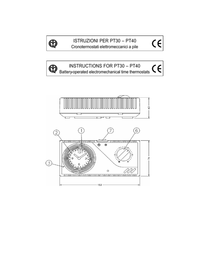
- La messa all’ora si effettua facendo ruotare il
disco (1), sul quale è incisa la lancetta dei minuti,
finché l’ora indicata è aggiornata.
- Ciclo 24 ore:
portare in corrispondenza dell’indice (3) l’ora
effettiva letta sul disco (2).
- Ciclo 7 giorni:
portare in corrispondenza dell’indice (3) il giorno
e le ore lette sul disco (2).
- Infine effettuare la messa all’ora precisa sul
quadrante delle 12 ore.
- ATTENZIONE: su entrambi i tipi è necessario
rimettere l’ora solo quando è segnalata la
variazione di orario estivo/invernale.
- To set the clock, rotate the disk (1) with the
minute hand until it shows the actual time.
- 24 hour cycle:
line up the actual time on the disk (2) with the
indicator (3).
- 7 day cycle:
line up the day and time on the disk (2) with the
indicator (3).
- Set the exact time on the 12 hour dial.
- CAUTION: on both types the time will need to be
reset only when changing from summer to winter
time and vice versa.
4 – PROGRAMMAZIONE
4 – PROGRAMMING
- Sul disco (2) dell’orologio si spostano verso
l’esterno i cavalieri a segmento compresi tra l’ora
iniziale e l’ora finale del funzionamento
desiderato a temperatura comfort.
- Questi periodi di funzionamento (cavalieri verso
l’esterno) rimangono evidenziati da un segmento
rosso.
- I restanti periodi (cavalieri verso il centro) hanno
il termostato escluso e nessun segmento
colorato.
- Possono essere programmati vari periodi
nell’arco del giorno. Chiamando operazione ogni
elemento di programma, si hanno le seguenti
possibilità:
- On the clock disk (2) slide the markers outwards
the initi al and final operating time required at
comfort temperature.
- These operating periods (markers towards the
outside) are highlighted by a red segment.
- During the remaining periods (markers towards
the centre) the thermostat will be switched off
and there will be no coloured segment.
- Various periods can be programmed during the
day. The following possibilities are available:
Cronotermostato
tipo
Time thermostat
type
Durata del ciclo
giorni
1
7
Cycle duration
days
1
7
n°
72
84
Max no. of operat. per cycle
no.
72
84
20
120
Min interval between 2 operat. minutes
20
120
N. max di operazioni per ciclo
Intervallo minimo tra 2 operaz. minuti
PT30
PT40
PT30
PT40
5 – REGOLAZIONI
5 – ADJUSTMENTS
- La rotazione della manopola (6) regola la
temperatura comfort.
- Il commutatore a 3 posizioni (7) permette di
scegliere le seguenti condizioni:
- To adjust comfort temperature, rotate the dial (6).
- The 3 position switch (7) allows you to choose
the following conditions:
POSIZIONE OROLOGIO
Programmazione automatica mediante l’orologio
programmato come indicato al punto 4.
POSIZIONE CENTRALE
Esclusione sia dell’orologio sia del termostato.
POSIZIONE SOLE
Temperatura comfort permanente (esclusione
dell’orologio).
POSITION CLOCK
Automatic programming via the programmed clock
shown in point 4.
CENTRAL POSITION
Both clock and thermostat switched off.
POSITION SUN
Permanent comfort temperature (clock switched off.

