OPTYMA32 -T
Elettrovalvole
Serie 2500
Fissaggi
24 VDC ± 10% PNP
1,2 Watt
da vuoto fino a 10 bar max.
da 3 a 7 bar max.
-5°C +50°C
IP 65
Aria filtrata e lubrificata o non
(se lubrificata la lubrificazione
deve essere continua)
Caratteristiche
funzionali
Tensione di alimentazione
Assorbimento elettropiloti
Pressione di lavoro condotti valvola (1-11)
Pressione di alimentazione condotto elettropiloti (12-14)
Temperatura di impiego
Grado di protezione
Fluido
Fissaggio dall’alto
49
+
Fissaggio su guida DIN
Ingombro massimo in funzione dei posti valvola
64
(N
°P
os
+
(N
°P
os
izio
ni
izio
ni
x1
9)
x1
9)
Attenzione : Per applicazioni a basse temperature l’aria deve essere opportunamente essiccata
,5
ø5
LED STATO ELETTROVALVOLA
(LED ACCESO =
TARGHETTE REMOVIBILI
PILOTA IN TENSIONE)
PERSONALIZZABILI DALL’UTENTE
Azionamento manuale
NOTA: Si raccomanda di riportare il comando manuale nella posizione iniziale dopo ogni utilizzo
1
AZIONAMENTI MANUALI
ELETTROVALVOLA
2
SIMBOLO PNEUMATICO
Premere per azionamento
(al rilascio il manuale viene riposizionato)
VITE DI FISSAGGIO
CODICE DI ORDINAZIONE
ALLA SOTTOBASE
Premere e poi ruotare per ottenere
la funzione bistabile
Installazione Valvole
CODICE BREVE FUNZIONE
CONDOTTI DI ALIMENTAZIONE
ELETTROVALVOLE (CONNESSIONI 1) - Ø 12
CONDOTTO SCARICO
ELETTROPILOTI - Ø8
CONDOTTO ALIMENTAZIONE
ELETTROPILOTI - Ø8
Aggancio moduli
UTILIZZI ELETTROVALVOLA (BOCCHE 2 E 4)
Ø8, Ø6, Ø4, G1/8”
Si consiglia l’impiego di
cacciavite a punta piana 1x5,5
CONDOTTI DI SCARICO ELETTROVALVOLE
(CONNESSIONI 3 E 5) - Ø12
Corrispondenza PIN per batteria montata su configurazione mista di basi per monostabile e bistabile
CONNESSIONE ELETTRICA
1
3
5
4
7
10
11
12
13
14
15
PIN 1 = PILOTA 14 EV POS.1
PIN 2 = PILOTA 12 EV POS.1
PIN 3 = PILOTA 14 EV POS.2
PIN 4 = PILOTA 14 EV POS.3
PIN 5 = PILOTA 14 EV POS.4
PIN 6 = PILOTA 12 EV POS.4
PIN 7 = PILOTA 14 EV POS.5
PIN 8 = PILOTA 14 EV POS.7
PIN 9 = PILOTA 14 EV POS.8
PIN 10 = PILOTA 14 EV POS.9
PIN 11 = PILOTA 14 EV POS.10
PIN 12 = PILOTA 14 EV POS.11
PIN 13 = PILOTA 12 EV POS.11
PIN 14 = PILOTA 14 EV POS.12
PIN 15 = PILOTA 12 EV POS.12
PIN 1
PIN 2
PIN 3
PIN 4
PIN 5
PIN 6
PIN 7
PIN 8
PIN 9
PIN 10
PIN 11
PIN 12
CONNETTORE FEMMINA A VASCHETTA SUB-D 25 POLI
PIN 13
PIN 13
PIN 12
PIN 11
PIN 10
PIN 9
PIN 8
PIN 7
PIN 6
PIN 5
PIN 4
PIN 3
PIN 2
CONNETTORE MASCHIO A VASCHETTA SUB-D 25 POLI
PIN 1
PIN 19
PIN 18
PIN 17
PIN 16
PIN 15
PIN 14
PIN 13
PIN 12
PIN 11
PIN 10
PIN 9
PIN 8
PIN 7
PIN 6
PIN 5
PIN 4
PIN 3
PIN 2
PIN 1
9
CONNESSIONE ELETTRICA DI USCITA
(SE PRESENTE)
CONNESSIONI ELETTRICHE DI INGRESSO
CONNETTORE MASCHIO A VASCHETTA SUB-D 37 POLI
8
6
2
POS.
1
3
2
4
5
6
7
8
9
10
11
12
1 - 32 = SEGNALI
33 - 35 = COMUNE
36 - 37 = LINEA PASSANTE
1 - 22 = SEGNALI
23 - 24 = COMUNE
25 = LINEA PASSANTE
PIN 14
PIN 15
PIN 16
PIN 17
PIN 18
PIN 19
PIN 20
PIN 21
PIN 22
PIN 23
PIN 24
PIN 25
PIN 25
PIN 24
PIN 23
PIN 22
PIN 21
PIN 20
PIN 19
PIN 18
PIN 17
PIN 16
PIN 15
PIN 14
PIN 37
PIN 36
PIN 35
PIN 34
PIN 33
PIN 32
PIN 31
PIN 30
PIN 29
PIN 28
PIN 27
PIN 26
PIN 25
PIN 24
PIN 23
PIN 22
PIN 21
PIN 20
Corrispondenza PIN per batteria montata su sole basi per bistabile.
1
1 - 22 = SEGNALI
23 - 24 = COMUNE
25 = LINEA PASSANTE 24V
5
3
2
4
7
6
9
8
11
10
13
12
15
14
17
16
19
PIN 1 = PILOTA 14 EV POS.1
PIN 2 = PILOTA 12 EV POS.1
PIN 3 = PILOTA 14 EV POS.2
PIN 4 = NON COLLEGATO
PIN 5 = PILOTA 14 EV POS.3
PIN 6 = NON COLLEGATO
PIN 7 = PILOTA 14 EV POS.4
PIN 8 = PILOTA 12 EV POS.4
PIN 9 = PILOTA 14 EV POS.5
PIN 10 = NON COLLEGATO
PIN 11 = PILOTA 14 EV POS.7
PIN 12 = NON COLLEGATO
PIN 13 = PILOTA 14 EV POS.8
PIN 14 = NON COLLEGATO
PIN 15 = PILOTA 14 EV POS.9
PIN 16 = NON COLLEGATO
PIN 17 = PILOTA 14 EV POS.10
PIN 18 = NON COLLEGATO
PIN 19 = PILOTA 14 EV POS.11
PIN 20 = PILOTA 12 EV POS.11
PIN 21 = PILOTA 14 EV POS.12
PIN 22 = PILOTA 12 EV POS.12
21
18
20
22
10
11
12
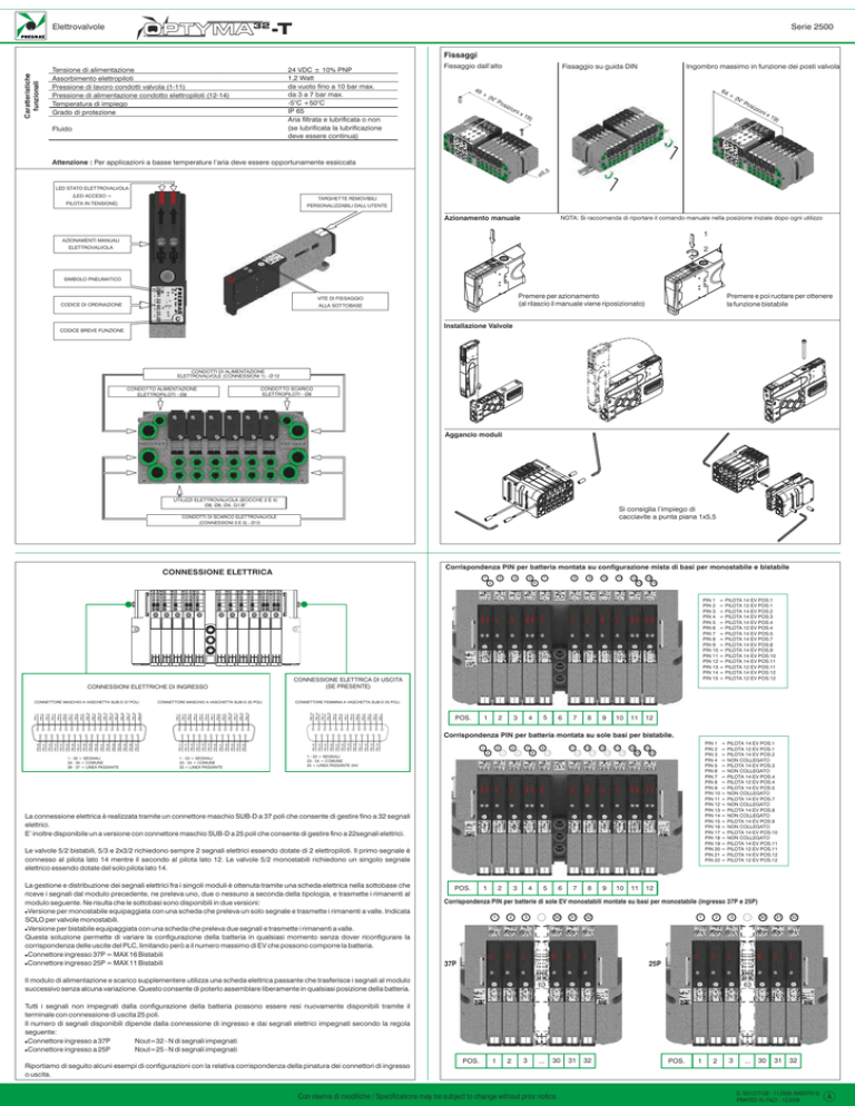
La connessione elettrica è realizzata tramite un connettore maschio SUB-D a 37 poli che consente di gestire fino a 32 segnali
elettrici.
E’ inoltre disponibile un a versione con connettore maschio SUB-D a 25 poli che consente di gestire fino a 22segnali elettrici.
Le valvole 5/2 bistabili, 5/3 e 2x3/2 richiedono sempre 2 segnali elettrici essendo dotate di 2 elettropiloti. Il primo segnale è
connesso al pilota lato 14 mentre il secondo al pilota lato 12. Le valvole 5/2 monostabili richiedono un singolo segnale
elettrico essendo dotate del solo pilota lato 14.
La gestione e distribuzione dei segnali elettrici fra i singoli moduli è ottenuta tramite una scheda elettrica nella sottobase che
riceve i segnali dal modulo precedente, ne preleva uno, due o nessuno a seconda della tipologia, e trasmette i rimanenti al
modulo seguente. Ne risulta che le sottobasi sono disponibili in due versioni:
!Versione per monostabile equipaggiata con una scheda che preleva un solo segnale e trasmette i rimanenti a valle. Indicata
SOLO per valvole monostabili.
!Versione per bistabile equipaggiata con una scheda che preleva due segnali e trasmette i rimanenti a valle.
Questa soluzione permette di variare la configurazione della batteria in qualsiasi momento senza dover riconfigurare la
corrispondenza delle uscite del PLC, limitando però a il numero massimo di EV che possono comporre la batteria.
!Connettore ingresso 37P = MAX 16 Bistabili
!Connettore ingresso 25P = MAX 11 Bistabili
POS.
1
3
2
4
5
6
7
8
9
Corrispondenza PIN per batterie di sole EV monostabili montate su basi per monostabile (ingresso 37P e 25P)
1
2
3
...
30
31
32
37P
1
2
3
...
30
31
32
1
2
3
...
30
31
32
25P
Il modulo di alimentazione e scarico supplementere utilizza una scheda elettrica passante che trasferisce i segnali al modulo
successivo senza alcuna variazione. Questo consente di poterlo assemblare liberamente in qualsiasi posizione della batteria.
Tutti i segnali non impegnati dalla configurazione della batteria possono essere resi nuovamente disponibili tramite il
terminale con connessione di uscita 25 poli.
Il numero di segnali disponibili dipende dalla connessione di ingresso e dai segnali elettrici impegnati secondo la regola
seguente:
!Connettore ingresso a 37P
Nout=32 - N di segnali impegnati
!Connettore ingresso a 25P
Nout=25 - N di segnali impegnati
Riportiamo di seguito alcuni esempi di configurazioni con la relativa corrispondenza della pinatura dei connettori di ingresso
o uscita.
POS.
1
2
3
...
30
Con riserva di modifiche / Specifications may be subject to change without prior notice.
31
32
POS.
D. IS012/IT-GB - 11/2009 (IMBSTR12)
PRINTED IN ITALY - 12/2009
A
OPTYMA32 -T
Solenoid Valves
Series 2500
Fastening
24 VDC ± 10% PNP
1,2 Watt
da vuoto fino a 10 bar max.
da 3 a 7 bar max.
-5°C +50°C
IP 65
Aria filtrata e lubrificata o non
(se lubrificatala lubrificazione
deve essere continua)
Technical
characteristics
Voltage
Pilot consuption
Valve working pressure (1-11)
Pilot working pressure (12-14)
Operating temperature
Protection degree
Fluid
Top fastening
49
+
DIN rail fastening
Max size based on the number of valves
64
(N
°P
os
+
(N
°P
os
itio
ns
itio
x1
9)
ns
x1
9)
Attention: dry air must be used for applications below 0°C"
,5
ø5
PILOT STATE LED
(LED ON =
REMOVABLE
ACTUATED PILOT)
CUSTOMIZABLE LABELS
Manual override
NOTE: It is strongly recommended to replace the original position after the use.
1
VALVE MANUAL
2
OVER-RIDE
PNEUMATIC SYMBOL
Push to actuate
(when released it moves back to the original
position)
VALVE COUPLING
SCREW
ORDERING CODE
Push and turn to get the bistable
function
Valve Installation
SHORT FUNCTION CODE
VALVE SUPPLY PORTS - CONNECTIONS 1 - Ø 12
PILOT SUPPLY PORT - CONNECTION - Ø8
PILOT EXHAUST PORTS - CONNECTION - Ø8
Manifold assembly
VALVE OUTLET - CONNECTIONS
2 & 4 - Ø8, Ø6, Ø4, G1/8”
The use of a flat screw driver
(1x5,5) is recommended
VALVE EXHAUST PORTS - (CONNECTIONS 3 & 5) - Ø12
PIN layout for a battery assembled on a mixed configuration of monostable/bistable bases
ELECTRICAL CONNECTION
1
3
5
4
7
10
11
12
13
14
15
PIN 1 = PILOT 14 EV POS.1
PIN 2 = PILOT 12 EV POS.1
PIN 3 = PILOT 14 EV POS.2
PIN 4 = PILOT 14 EV POS.3
PIN 5 = PILOT 14 EV POS.4
PIN 6 = PILOT 12 EV POS.4
PIN 7 = PILOT 14 EV POS.5
PIN 8 = PILOT 14 EV POS.7
PIN 9 = PILOT 14 EV POS.8
PIN 10 = PILOT 14 EV POS.9
PIN 11 = PILOT 14 EV POS.10
PIN 12 = PILOT 14 EV POS.11
PIN 13 = PILOT 12 EV POS.11
PIN 14 = PILOT 14 EV POS.12
PIN 15 = PILOT 12 EV POS.12
PIN 1
PIN 2
PIN 3
PIN 4
PIN 5
PIN 6
PIN 7
PIN 8
PIN 9
PIN 10
PIN 11
PIN 12
FEMALE SUB-D 25 POLES CONNECTOR
PIN 13
PIN 13
PIN 12
PIN 11
PIN 10
PIN 9
PIN 8
PIN 7
PIN 6
PIN 5
PIN 4
PIN 3
PIN 2
PIN 1
PIN 19
PIN 18
PIN 17
PIN 16
PIN 15
MALE SUB-D 25 POLES CONNECTOR
PIN 14
PIN 13
PIN 12
PIN 11
PIN 10
PIN 9
PIN 8
PIN 7
PIN 6
PIN 5
PIN 4
PIN 3
PIN 2
PIN 1
9
EXIT ELECTRICAL CONNECTION
(OPTIONAL)
INPUT ELECTRICAL CONNECTIONS
MALE SUB-D 37 POLES CONNECTOR
8
6
2
POS.
1
3
2
4
5
6
7
8
9
10
11
12
1 - 32 =SIGNALS
33 - 35 =COMMON
36 - 37 =PASSING LINE
1 - 22 =SIGNALS
23 - 24 =COMMON
25 =PASSING LINE
PIN 14
PIN 15
PIN 16
PIN 17
PIN 18
PIN 19
PIN 20
PIN 21
PIN 22
PIN 23
PIN 24
PIN 25
PIN 25
PIN 24
PIN 23
PIN 22
PIN 21
PIN 20
PIN 19
PIN 18
PIN 17
PIN 16
PIN 15
PIN 14
PIN 37
PIN 36
PIN 35
PIN 34
PIN 33
PIN 32
PIN 31
PIN 30
PIN 29
PIN 28
PIN 27
PIN 26
PIN 25
PIN 24
PIN 23
PIN 22
PIN 21
PIN 20
PIN layout for a battery assembled just on bistable bases
1
5
3
2
1 - 22 =SIGNALS
23 - 24 =COMMON
25 =24V PASSING LINE
4
7
6
9
8
11
10
13
12
15
14
17
16
19
PIN 1 = PILOT 14 EV POS.1
PIN 2 = PILOT 12 EV POS.1
PIN 3 = PILOT 14 EV POS.2
PIN 4 = NOT CONNECTED
PIN 5 = PILOT 14 EV POS.3
PIN 6 = NOT CONNECTED
PIN 7 = PILOT 14 EV POS.4
PIN 8 = PILOT 12 EV POS.4
PIN 9 = PILOT 14 EV POS.5
PIN 10 = NOT CONNECTED
PIN 11 = PILOT 14 EV POS.7
PIN 12 = NOT CONNECTED
PIN 13 = PILOT 14 EV POS.8
PIN 14 = NOT CONNECTED
PIN 15 = PILOT 14 EV POS.9
PIN 16 = NOT CONNECTED
PIN 17 = PILOT 14 EV POS.10
PIN 18 = NOT CONNECTED
PIN 19 = PILOT 14 EV POS.11
PIN 20 = PILOT 12 EV POS.11
PIN 21 = PILOT 14 EV POS.12
PIN 22 = PILOT 12 EV POS.12
21
18
20
22
10
11
12
The electrical connection is achieved by a male SUB-D 37 pin connector which is able to manage up to 32 solenoid pilots.
As an option, a male SUB-D 25 pin connector is also available. This connectror can manage up to 22 solenoid pilots.
Bistable 5/2 valve, 5/3 valves and 2x3/2 always require 2 electrical signals, since they are equipped with 2 electrical pilots. The
first signal is connected with side 14 pilot, while the second is connected with side 12. Monostable 5/2 valves require a single
electrical signal since they are equipped just with side 14 electrical pilot.
The management and distribution of the electrical signals between each valve is obtained by a PCB which receives the
signals from the previous module, uses one, two or none according with the type, and carries the remaining ones forward to
the next module. As a result, modular sub-bases are available in 2 versions:
!Monostable version uses a PCB which uses one sigle signal and carries forward the remaining ones. It is suitable ONLY for
monostable valves.
!Bistable version uses a PCB which uses 2 signals and carries forward the remaining ones.
This second solution allows the modification of the manifold (replacement of monostable valves with bistable for example)
without having to reset the PLC output layout. On the other hand this solution limits the maximum number of valves:
!37P input connector = 16 bistable MAX
!25P input connector = 11 bistable MAX
POS.
1
3
2
4
5
6
7
8
9
PIN layout for batteries of monostable EV assembled on monostable bases (37P and 25P input)
1
2
3
...
30
31
32
37P
1
2
3
...
30
31
32
1
2
3
...
30
31
32
25P
Intermediate supply & exhaust module is equipped with a dedicated PCB which carries forward all electrical signals using
none and allows to place the module anywhere in the battery layout.
All signals not used for the battery configuration can be available for other applications by using a exit manifold equipped with
a female SUB-D 25 pin connector.
The number ov available signals depends on the input connection:
!37 pin input connector Nout=32 - N of allocated signals
!25 pin input connector Nout=25 - N of allocated signals
See following configuration examples and relevant pin correspondence for input and output SUB-D connector.
POS.
1
2
3
...
30
Con riserva di modifiche / Specifications may be subject to change without prior notice.
31
32
POS.
D. IS012/IT-GB - 11/2009 (IMBSTR12)
PRINTED IN ITALY - 12/2009
A

