®
I
GB
AVVIATORI DIRETTI
LOVATO S.P.A.
COMPONENTI E SISTEMI
PER AUTOMAZIONE
24020 GORLE (BERGAMO) ITALIA
VIA DON E. MAZZA, 12
TEL.: 035 4282111
TELEFAX (Nazionale): 035 4282200
TELEFAX (International): +39 035 4282400
Web
www.lovatospa.it
E-mail [email protected]
I17.I.GB.D.10-99
D
DIRECT-ON-LINE
STARTERS
DIREKT-STARTER
Contenitore in materiale isolante IP54.
IP54 insulated enclosure.
In Kunstoffgehäuse IP54
VERSIONI E POTENZE DI IMPIEGO
La tabella seguente fornisce le versioni consigliate e le relative caratteristiche.
VERSIONS AND UTILISATION POWER
The following table indicates the
recommended versions and the relative characteristics.
VERSIONEN UND NENNLEISTUNG
Die folgende Tabelle zeigt die Serienversionen.
M0BRF/...
Potenza d'impiego / Utilisation power / Nennleistung
Versioni
Versions
Version
220/230V
[kW]
[A]
380/400V
[kW]
415V
[kW]
M0BRF/R11...
12
0,37-3
0,37-5,5
0,37-5,5
0,37-5,5
500.000
M0BRF/P11
12
0,37-3
0,37-5,5
0,37-5,5
0,37-5,5
500.000
M0BRF/PA11
12
0,37-3
0,37-5,5
0,37-5,5
0,37-5,5
500.000
SIGNIFICATO DELLE VERSIONI
...../R..
Con ripristino
...../P..
Con MARCIA e
ARRESTO/RIPRISTINO
...../PA.. ❶ Con MARCIA e
ARRESTO/RIPRISTINO
❶ In tale versione il pulsante di MARCIA ha la posizione stabile (tale caratteristica è ottenuta montando
l'accessorio G227); infatti dopo averlo premuto rimane agganciato e lo sgancio avviene premendo il pulsante di ARRESTO/RIPRISTINO.
Ciò consente di realizzare un comando a contatto permanente con fermo ed inserzione sul fronte; il
comando di inserito è reso evidente dalla posizione
assunta dal tasto di MARCIA.
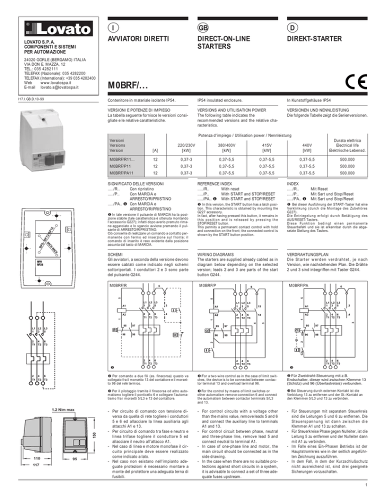
SCHEMI
Gli avviatori, a seconda della versione devono
essere cablati come indicato negli schemi
sottoriportati. I conduttori 2 e 3 sono parte
del pulsante G244.
REFERENCE INDEX
...../R..
With reset
...../P..
With START and STOP/RESET
...../PA.. ❶ With START and STOP/RESET
INDEX
...../R..
...../P..
...../PA.. ❶
❶ In this version, the START button has a latch position. This characteristic is obtained by mounting the
G227 accessory.
In fact, after having pressed this button, it remains in
this position and is released by pressing the
STOP/RESET button.
This permits a permanent contact control with hold
and connection on the front; the connected control is
shown by the START button position.
❶ Bei dieser Ausführung der START-Taster hat eine
Verklinkung (durch die Montage des Zubehöres
G227).
Die Entriegelung erfolgt durch Betätigung des
AUS/RESET-Tasters.
Diese Funktion bedingt einen permanente
Steuerbefehl und sie ist erkennbar durch die abgesetzte Stellung des Tasters.
WIRING DIAGRAMS
The starters are supplied already cabled as in
diagram below depending on the selected
version; leads 2 and 3 are parts of the start
button G244.
VERDRAHTUNGSPLAN
Die Starter werden verdrahtet, je nach
Version, wie nachstehenden Plan. Die Drähte
2 und 3 sind inbegriffen mit Taster G244.
M0BRF/P
M0BRF/PA
6
5
5
6
4
A2
L1 L2 L3
1 3 5
2 4 6
T1 T2 T3
4
95
2 4
T1 T2
6
T3
97
95
A1
14
A2
95
97
98
96
98
2
96
2 4 6
T1 T2 T3
6
T3
150
1.2 N/m max
110
.4
97
95
98
2 4 6
T1 T2 T3
2 4 6
T1 T2 T3
❷
117
2 4 6
T1 T2 T3
.3
R
96
2 4
T1 T2
L1 L2 L3
1 3 5
2
L3
5
13
3
A1
1
1
3
1
2 4 6
T1 T2 T3
A2
6
3
L1 L2 L3
1 3 5
A1
Mit Reset
Mit Sart und Stop/Reset
Mit Sart und Stop/Reset
5
M0BRF/R
L1 L2
1 3
Durata elettrica
Electrical life
Elektrische Lebensd.
440V
[kW]
❸
❷ Per comando a due fili (es. finecorsa) questo va
collegato fra il morsetto 13 del contattore e il morsetto 96 del relè termico.
❷ For a two-wire control as in the case of limit switches, the device is to be connected between contactor terminal 13 and overload terminal 96.
❷ Für Zweidraht-Steuerung mit z.B.
Endschalter, dieser wird zwischen Klemme 13
(Schütz) und 96 (Überlastrelais) verbunden.
❸ Per il pilotaggio tramite il finecorsa od altro automatismo togliere il ponticello 6 e collegare l'automatismo fra i morsetti 5/L3 e 13 del contattore.
❸ For the control by means of limit switches or
other automatism remove connection 6 and connect
the automatism between contactor terminals 5/L3
and 13.
❸ Bei Steuerung durch externen Kontakt ist die
Verbidung 13 zu entfernen und der St.-Kontakt an
den Klemmen 5/L3 und 13 zu verbinden.
- Per circuito di comando con tensione diversa da quella di rete togliere i conduttori
5 e 6 ed allacciare la linea ausiliaria agli
attacchi A1 e 13.
- Per circuito di comando tra fase e neutro e
linea trifase togliere il conduttore 5 ed
allacciare il neutro all'attacco A1.
- Nel caso di linea e motore monofase il circuito principale deve essere realizzato
come indicato a lato.
- Nel caso non esistano nell'impianto adeguate protezioni è necessario montare a
monte del protettore una adeguata terna di
fusibili.
- For control circuits with a voltage other
than the mains value, remove leads 5 and 6
and connect the auxiliary line to terminals
A1 and 13.
- For control circuit between phase, neutral
and three-phase line, remove lead 5 and
connect neutral to terminal A1.
- In case of one-phase line and motor, the
main circuit should be connected as in the
side drawing.
- In the case when there are no suitable protections against short circuits in a system,
it is advisable to connect a set of three adequate fuses upstream.
- Für Steuerungen mit separatem Steuerkreis
sind die Leitungen 5 und 6 zu entfernen. Die
Steuerspannung ist dann zwischen die
Klemmen A1 und 13 zu schalten.
- Für Steuerkreise Phase gegen Nulleiter, ist die
Leitung 5 zu entfernen und der Nulleiter dann
mit A1 zu verbinden.
- Im Falle eines Ein-Phasen Betriebs ist der
Hauptstromkreis wie in der seitlich angeführten Zeichnung auszuführen.
- In dem Fall, in dem der Kurzschlußschutz
nicht ausreichend ist, sind drei geeignete
Sicherungen vorzuschalten.
1
INSTALLAZIONE
L'ingresso dei cavi può avvenire dall'alto, dal
basso e dal piano posteriore; affinchè il grado
di protezione rimanga invariato è necessario
sfondare i soli diaframmi di utiizzare e completare gli imbocchi filettati con pressacavi da
5/8 Gas.
NOTA. La rottura dei diaframmi se richiesta
presenta una certa resistenza dovuta al materiale impiegato pertanto, per facilitare tale
operazione è bene utilizzare un tubo in ferro
avente diametro di poco inferiore al foro o, un
robusto cacciavite agendo come indicato
nella figura a lato.
INSTALLATION
The cables enter through the top, the bottom
and even through the rear. To maintain the
degree of protection, only the necessary
diaphragms should be knocked out and the
threaded lead-ins completed with 5/8 Gas
cable glands.
NOTE. The knocking out of the diaphragms
presents a certain resistance caused by the
material used. Therefore, to simplify this operation, it is better to use an iron tube having a
diameter a little smaller than the hole or a
strong screw-driver and preceed in the manner indicated the side figure.
INSTALLATION
Die Anschlüsse sind von oben, von unten
oder von hinten einzuführen. Zur Aufrechthaltung des Schutzgrades ist es notwendig
Kabelverschraubungen 5/8 Gas zu verwenden.
ACHTUNG: Zum Ausbrechen des Loch's fùr
die Verschraubung ist, ein Stahlrohr, mit
einem etwas kleinerem Durchmesser als das
Loch zu verwenden, oder ein starker
Schraubendreher. Dabei ist wie in der
Abbildung oben links vorzugehen.
COMPILAZIONE DATI DI TARGA
Ultimata l'installazione scrivere con un pennarello i dati di targa come esemplificato a
lato.
LABELLED DATA COMPLETION
When the installation is completed, write with
a pen the labelled data, as per side example.
BESCHRIFTEN MIT DATEN
Wenn die Installation abgeschlossen ist, schreiben Sie die Installations-Daten auf das
selbsklebendes Schild und kleben Sie dieses
auf die Front des Gehäusedeckels.
ELEMENTI DEL CONTENITORE
ENCLOSURE ELEMENTS
KOMPONENTEN GEHÄUSE
Quantità / Quantity / Menge
Descrizione / Description / Beschreibung
- Calotta senza pulsante
- Calotta con pulsante reset
- Calotta con pulsanti marcia
e stop/reset
- Base
- Attacco di terra
- Viti fissaggio contattore
MC6-MC9 (2,9x9,5)
- Viti fissaggio contattore
BF9-12-16 (2,9x13)
- Pulsante G244
- Passacavi
- Cover without button
- Cover with reset button
- Cover with sart and
stop/reset buttons
- Base
- Earth terminal
- Fixing screw for contactors
MC6-MC9 (2,9x9,5)
- Fixing screw for contactors
BF9-12-16 (2,9x13)
- G244 button
- Fairleads
TABELLA RIASSUNTIVA
VERSIONI REALIZZATE DI SERIE
(Avviatore diretto) M0BRF/R11
(Dol Starter)
M0BRF/P11
(Direkt-Starter)
- Deckel ohne Drucktaster
- Deckel mit Reset-Taster
- Deckel mit Start und
Stop/Reset Taster
- Unterteil
- Erdungsklemme
- Befestigungsschrauben
MC6-MC9 (2,9x9,5)
- Befestigungsschrauben
BF9-12-16 (2,9x13)
- G244 Drucktaster
- Kabelstopfen
SUMMARY TABLE
SERIAL VERSIONS
=
M0R (Contenitore)
M0P (Housing)
(Gehäuse)
M0
MOR
M0P
1
–
–
–
1
–
–
–
1
1
1
2
1
1
2
1
1
2
2
2
2
–
3
–
3
1
2
SAMMELTAFEL
STANDARD VERSION
+
BF9.10 (Contattore)
BF9.10 (Contactor)
(Schütz)
+
RF25 (Relè termico)
RF25 (Overload relay)
(Überlastrelais)
ALTRE VERSIONI REALIZZABILI
Contattore + Relè termico
MC6
RF9
MC9
RF9
BF12
RF25
BF16
RF25
OTHER POSSIBLE VERSIONS
Contactor + Overload Relay
MC6
RF9
MC9
RF9
BF12
RF25
BF16
RF25
ANDRE MÖGLICHE VERSIONEN
Schütz +
Überlastrelais
MC6
RF9
MC9
RF9
BF12
RF25
BF16
RF25
MONTAGGIO
- Il contattore si monta a vite.
- Il relè termico si fissa direttamente al contattore.
- Il pulsante G244 si monta a scatto sul fianco destro del relè termico come indicato in
figura a lato.
- L'accessorio G227 che trasforma il pulsante di MARCIA in stabile va montato nella
parte interna della calotta in corrispondenza
dei tasti meccanici come indicato in figura.
Dopo averlo innestato nei due riferimenti A
va bloccato con la vite B che deve essere
chiusa a fondo.
ASSEMBLY
- The contactor is screw fixed.
- The thermal relay is directly fixed onto the
contactor.
- The G244 push button is snapped onto the
right side of the thermal relay as illustrated
in the side figure.
- The G227 accessory which transforms the
START button into a latching one is mounted on the cover correspondent to the
mechanical button as shown in the figure.
After having inserted the two reference A, it
is to be locked by completely tightening
screw B.
MONTAGE
- Der Schütz wird mit Schrauben befestigt
- Der Überlastrelais wird am Schütz montiert
- Der Drucktaster G244 wird auf der rechten
Seite des Überlastrelais aufgeschnappt.
Siehe Abbildung seitlich.
- Bei der Verwendung der Verlinkung G227
an den START-Taster (siehe Figur), diese
wird unter den Taster, bei den
Markierungen A, eingefügt und durch
Schraube B befestigt.

![Ricerca nr. 1 [MS WORD 395 KB]](http://s1.studylibit.com/store/data/000076742_1-2ede245e00e21c823e517529e1c3be46-300x300.png)

