cod. +050000735 - rel. 1.1 - dated 21.09.2007
HYVC000U0* - scheda espansione 0...10 V/triac/relè per controllo elettronico e-drofan FTU
HYVC000U0* - 0 to 10 V/triac/relay expansion board for e-drofan FTU electronic controller
Introduzione
Questo dispositivo permette al controllo elettronico e-drofan FTU (Cod. HYFT00000*)
di controllare i carichi aggiuntivi al ventilatore: ventilatori e serrande modulanti,
resistenze ecc.
Istruzioni per il montaggio e l’installazione
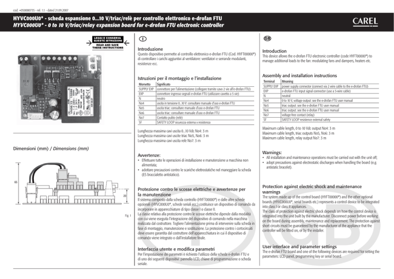
Morsetto
SUPPLY EXP
EXP
N
No4
No5
No6
No7
SF
Significato
connettore per l’alimentazione (collegare tramite cavo 2 vie all’e-drofan FTU)
connettore ingresso segnali e-drofan FTU (utilizzare cavetto a 5 vie)
neutro
uscita in tensione 0...10 V: consultare manuale d’uso e-drofan FTU
uscita triac: consultare manuale d’uso e-drofan FTU
uscita triac: consultare manuale d’uso e-drofan FTU
Contatto pulito (relè)
SAFETY LOOP sicurezza esterna x resistenza
Lunghezza massima cavi uscita 0...10 Vdc No4: 3 m
Lunghezza massima cavi uscite triac No5, No6: 3 m
Lunghezza massima cavi uscita relè No7: 3 m
Dimensioni (mm) / Dimensions (mm)
Avvertenze:
• Effettuare tutte le operazioni di installazione e manutenzione a macchina non
alimentata;
• adottare precauzioni contro le scariche elettrostatiche nel maneggiare la scheda
(ES braccialetto antistatico).
Introduction
This device allows the e-drofan FTU electronic controller (code HYFT00000*) to
manage additional loads to the fan: modulating fans and dampers, heaters etc.
Assembly and installation instructions
Terminal
SUPPLY EXP
EXP
N
No4
No5
No6
No7
SF
Meaning
power supply connector (connect via 2 wire cable to the e-drofan FTU)
e-drofan FTU input signal connector (use a 5-wire cable)
neutral
0 to 10 V, voltage output: see the e-drofan FTU user manual
triac output: see the e-drofan FTU user manual
triac output: see the e-drofan FTU user manual
voltage-free contact (relay)
SAFETY LOOP resistence external safety
Maximum cable length, 0 to 10 Vdc output No4: 3 m
Maximum cable length, triac outputs No5, No6: 3 m
Maximum cable length, relay output No7: 3 m
Warnings:
• All installation and maintenance operations must be carried out with the unit off;
• adopt precautions against electrostatic discharges when handling the board (e.g.
antistatic bracelet).
65
20
Fig. 1
Protezione contro le scosse elettriche e avvertenze per
la manutenzione
Il sistema composto dalla scheda controllo (HYFT00000*) e dalle altre schede
opzionali (HYVC000U0*, schede seriali ecc.) costituisce un dispositivo di comando da
incorporare in apparecchiature di tipo classe I o classe II.
La classe relativa alla protezione contro le scosse elettriche dipende dalla modalità
con cui viene eseguita l’integrazione del dispositivo di comando nella macchina
realizzata dal costruttore. Togliere l’alimentazione prima di intervenire sulla scheda in
fase di montaggio, manutenzione e sostituzione. La protezione contro i cortocircuiti
deve essere garantita dal costruttore dell’apparecchiatura in cui il dispositivo di
comando viene integrato o dall’installatore finale.
Interfaccia utente e modifica parametri
Per l’impostazione dei parametri è richiesto l’utilizzo della scheda e-drofan FTU e
di uno dei seguenti dispositivi: pannello LCD, chiave di programmazione o scheda
seriale.
Protection against electric shock and maintenance
warnings
The system made up of the control board (HYFT00000*) and the other optional
boards (HYVC000U0*, serial boards etc.) represents a control device to be integrated
into class I or class II appliances.
The class of protection against electric shock depends on how the control device is
integrated into the unit built by the manufacturer. Disconnect power before working
on the board during assembly, maintenance and replacement. The protection against
short circuits must be guaranteed by the manufacturer of the appliance that the
controller will be fitted on, or by the installer.
User interface and parameter settings
The e-drofan FTU board and one of the following devices are required for setting the
parameters: LCD panel, programming key or serial board.
Caratteristiche tecniche
160
52.81
74.48
32.71
Alimentazione
16.23
16.23
Uscita 0...10V No4
HYVC000U0*
95
57.90
58.32
95
ingombro scheda
HYFT00000*
board overall
dimensions
Morsetti a vite
Uscite triac No5, No6
20.87
20.45
Uscita relè No7
Isolamenti
52.81
62.99
44.19
160
Fig. 2
Schema di collegamento / Connection diagram
DIP
DI5
B1
B2
B3
230 Vac, range – 15...10 %; 50/60 Hz
Massima potenza assorbita: 5 VA
tensione max: 250 V
sezione cavi: 14-22 AWG
corrente max: vedere uscite No4-7
impedenza minima dello stadio di ingresso
dell’attuatore 0...10 Vdc = 10 Kohm
corrente max a 24 Vac (per singola uscita in
tensione): 0,09A
Tipo di azione dei triac: disconnessione elettronica
corrente massima a 250 Vac: - EN60730: Resistivo 10 A 100000 cicli
tipo di azione micro-interruzione dei relè: 1C
isolamento tra bassa e bassissima tensione: rinforzato
isolamento tra uscite triac in tensione (24 Vac) No5, No6: rinforzato
isolamento tra uscite triac in tensione No5, No6 e uscita relè No7:
rinforzato
Isolamento tra l’uscita 0-10 Vdc e l’uscita relè No7: rinforzato
Grado di protezione
Condizioni di immagazzinamento
Condizioni di funzionamento
Grado di inquinamento
Categoria di resistenza al calore e al fuoco
PTI dei materiali di isolamento
Periodo delle sollecitazioni elettriche delle
parti isolanti
IP00
-20T80 °C, umidità 80% U.R. non condensante
0T60 °C, umidità <90% U.R. non condensante
normale
D
tutti i materiali hanno PTI 250
lungo
EXP
Screw terminals
0 to 10 V output No4
Triac outputs No5, No6
Relay output No7
Insulation
230 Vac, range – 15 to 10 %; 50/60 Hz
Maximum power input: 5 VA
max voltage: 250 V
cable cross-section: 14-22 AWG
max current: see outputs No4-7
minimum impedance of the input stage
of the 0 to 10 Vdc actuator = 10 Kohm
max current at 24 Vac (for individual voltage output): 0.09A
type of action of the triac: electronic disconnection
maximum current at 250 Vac: - EN60730: Resistive 10 to 100000
cycles
type of relay micro-switching action: 1C
insulation between low and very low voltage parts: reinforced
insulation between triac outputs (24 Vac) No5, No6: reinforced
insulation between triac outputs No5, No6 and relay output No7:
reinforced
insulation between 0-10 Vdc output and relay output No7:
reinforced
Index of protection
Storage conditions
Operating conditions
Degree of pollution
Category of resistance to heat and fire
PTI of insulating materials
Period of stress across the insulating parts
IP00
-20T80 °C, humidity 80% RH non-condensing
0T60 °C, humidity <90% RH non-condensing
normal
D
all materials PTI 250
long
Smaltimento del prodotto
SUPPLY
EXP
L
No4 No5 N No6
Power supply
HYFT00000*
HYVC000U0*
N
Technical specifications
SF SF
L
N
N
N
No3
L’apparecchiatura (o il prodotto) deve essere oggetto di raccolta
separata in conformità alle vigenti normative locali in materia di
smaltimento
Disposal of the product
The appliance (or the product) must be disposed of separately in
compliance with the local standards in force on waste disposal
No7 No7
L
N
0...10 Vdc output
uscita in tensione
triac (24 Vac)
voltage output triac
uscita relè
relay output
HY
termico resistenza
heater cutout
Fig. 3
CAREL S.p.A.
Via dell’Industria, 11 – 35020 Brugine – Padova (Italy)
Tel. (+39) 0499716611 – Fax (+39) 0499716600 – www.carel.com – [email protected]
cod. +050000735 - rel. 1.1 - dated 21.09.2007

