Generatori AC-AC/DC
AC Power Sources
CARATTERISTICHE TECNICHE
TECHNICAL FEATURES
Tensione di alimentazione
115 o 230 ot 400 Vac ± 10% 50-60 Hz
Mains Input
115 or 230 or 400 Vac ± 10% 50-60 Hz
Regolazione di linea
migliore di 50 ppm della V di uscita per la variazione
ammessa in ingresso sia come generatore di AC sia come
alimentatore
Line regulation
better than 50 ppm of output V max for the allowed input
variation, both as AC Generator and as DC Power Supply
Tensione di uscita
regolabile nei modelli da “0” e la V max di targa (AC o DC)
con potenziometro a 10 giri
Output Voltage
adjustable models from “0” to max rated V (AC or DC)
with a 10 turn potentiometer
Regolazione al carico per V costante
da vuoto a pieno carico migliore di 0,5% sia come
generatore di AC sia come alimentatore DC
Load regulation for constant V
from no load to full load better than 0,5% both as AC
Power Source and as DC Power Supply
Corrente di uscita
regolabile attraverso un potenziometro a 10 giri, fra “0” e la
I max di targa
Output Current
adjustable with a 10 turn potentiometer from “0” to max
rated I
Regolazione al carico per I costante
migliore di 0,5% alla max corrente da “0” alla V max sia
come generatore di AC sia come alimentatore DC
Load regulation for constant I
better than 0,5% of I max from “0” to V max both as AC
Generator and as DC Power Supply
Frequenza di uscita
Regolabile secondo modello con potenziometro a 10 giri.
Output Frequency
adjustable from min to max rated frequency with a 10 turn
potentiometer
Stabilità della frequenza
migliore di ± 0,5%
Frequency stability
better than ± 0,5%
Distorsione della frequenza
misurata in “modo tensione”, migliore di 0,5%
Frequency distorsion
better than ± 0,5%, measured in “voltage mode”
Ronzio e rumore di fondo (uscita DC)
minore di 0,5% (rms) della V max
Ripple and noise (DC output)
better than ± 0,5% of V max
Coefficiente di temperatura
minore di 50 ppm/°C in “modo tensione”;
minore di 100 ppm/°C in “modo corrente”
Temperature coefficient
under 50 ppm/°C in “voltage mode”;
under 100 ppm/°C in “current mode”
Temperatura ambiente
di lavoro 0÷40°C
di magazzinamento -10÷50°C
Ambient temperature
work 0÷40°C
storage -10÷50°C
Raffreddamento
ventilazione forzata
Cooling
forced air
Garanzia anni
Ed. 03/2012
Years Warranty
Pag. 47
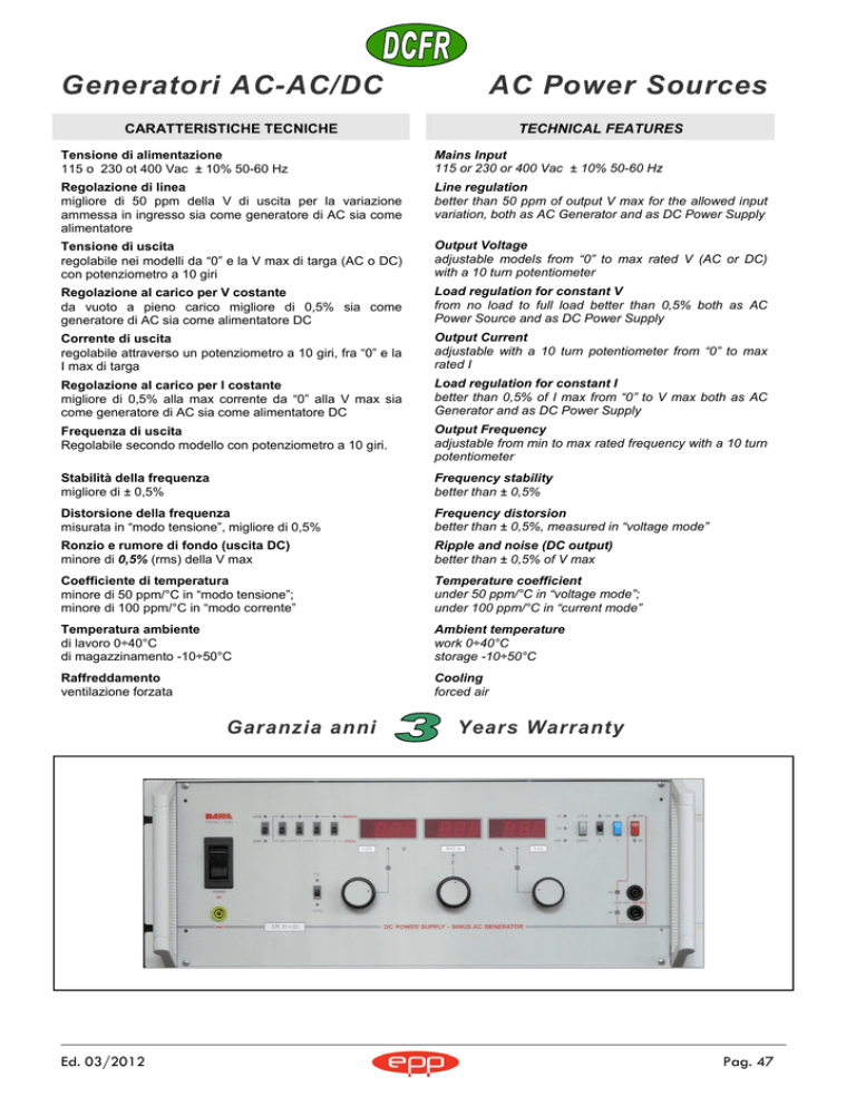
CONTROLLI SUL PANNELLO FRONTALE
FRONT PANEL CONTROLS
Power
Interruttore magnetotermico che accende l’apparecchio
Power
Breaker switching the equipment ON and OFF
ON
Comandi per l’abilitazione dell’uscita in modo controllato
P - interruttore a slitta che abilita l’uscita, funzione
segnalata con LED
S - pulsante in alternativa all’interruttore P da utilizzare
quando non si vuole che l’erogazione della tensione
avvenga in contemporanea all’azionamento dell’interruttore
Power
ON
Commands to enable output in controlled mode
P - slide switch that enables output, functions marked with
a LED
S - push-button alternative to P switch to be used to avoid
voltage output when Power switch is on .
DC/AC
Pulsante per scegliere se l’uscita deve erogare corrente
continua od alternata. Posizione segnalata da LED
DC/AC
Button to choose whether the output must be AC or DC.
Position marked by LEDs
Check
pulsanti per la taratura di V - A - F, con il generatore in
stand-by
Check
V - A - F set up push-buttons when the power supply is in
stand-by
OVP (Over Voltage Protection)
Allarme di sovratensione di uscita con inibizione del
generatore e immediata segnalazione luminosa
OVP (Over Voltage Protection)
Output overvoltage alarm inhibiting the generator with an
immediate LED signal
OT
allarme di temperatura pericolosa per la sezione di potenza
che disattiva l’erogazione del generatore con immediata
segnalazione luminosa
OT
Overtemperature alarm of power section inhibiting the
generator with an immediate LED signal
OL
allarme di sovraccarico o di corto circuito permanente in
uscita
OL
over load or permanent short circuit alarm on output
Local/Remote ON – F – V – A
interruttori a slitta per selezionare il tipo di programmazione
delle funzioni presenti sul generatore offrendo la scelta tra i
potenziometri sul frontale o i comandi dal connettore GPAC
o dall’interfaccia GPIB/RS (opzionale)
Local/Remote ON – F – V – A
Slide switches to select the type of function programming
on the generator by offering an option between the knobs
on the front panel controls or the GPAC or GPIB/RS
(optional) connector
GPAC/GPIB
Interruttori a slitta per programmare le funzioni presenti
attraverso il connettore GPAC o dall’interfaccia IEEE488 RS232/RS485 (opzionale), posti sul retro
GPAC/GPIB
Slide switches to program all functions through GPAC
connector or through i IEEE488 - RS232/RS485 interface
(optional), both on the back
Sezione V
Potenziometro e display (con precisione del 1,5%) che
indica la tensione di uscita erogata o, attraverso il pulsante
di Check, quella programmata. LED di “modo tensione”
Section V
Potentiometer and display (with accuracy of 1.5%)
showing output voltage or, by means of Check button,
programmed voltage. LED of “voltage mode”
F.S.
Selettore per commutare la tensione di uscita dal 50 al
100%. LED che indica il fondo scala scelto.
F.S.
Slide switch to choose output voltage F.S. from 50% to
100%. LED shows selected output range.
Sezione F
Potenziometro e display (con precisione dell’ 1,5%) che
indica la frequenza di uscita o, attraverso il pulsante di
Check, quella programmata.
Section F
Potentiometer and display (with accuracy of 1.5%)
showing output frequency or, by means of Check button,
programmed frequency
Sezione A
Potenziometro e display (con precisione dell’ 1,5%) che
indica la corrente erogata o, attraverso il pulsante di Check,
quella programmata. LED di “modo corrente”
Section A
Potentiometer and display (with accuracy of 1.5%)
showing output current or, by means of Check button,
programmed current. LED of “current mode”
GND
Boccola di terra
GND
Ground plug
AUX OUT
Boccole ausiliarie di uscita fino ad un massimo di 5 A
I LEDs “DC” ed “AC” indicano il tipo di uscita selezionato
ed il polo positivo dell’uscita in DC
AUX OUT
Auxliary plug to be used up to 5 A max
“DC” and “AC” LEDs indicate selected output and DC
positive output pole
Pag. 48
www.danasrl.it
CONTROLLI SUL PANNELLO POSTERIORE
BACK-PANEL CONTROLS
GPAC
Connettore “General Purpose Analog Control” per
programmare il generatore in modo remoto attraverso una
tensione analogica optoisolata 0 ÷ 10 Vdc per tutte le sue
funzioni e per la lettura dei feed-back (0 ÷ 10 Vdc)
proporzionali ai parametri di uscita e abilita o inibisce
l’uscita attraverso un segnale logico 0 - 5 Vdc
GPAC
“General Purpose Analog Control” connector to program
remotely the Power Source with 0 ÷ 10 Vdc analog
optically isolated voltage for all remote functions and to
read proportional to Voltage and Current feed-back and to
enable or inhibit output through a logic command 0 – 5
Vdc
GPIB/RS (opzione)
Connettori per interfaccia di programmazione IEEE488 e
RS232/485
GPIB/RS (option)
Connectors for programming standard interfaces IEEE488
and RS232/485
OUT
Uscita di potenza
OUT
Power output
OPZIONI
OPTIONS
PS
interfaccia per programmare il generatore con standard
IEEE488/RS232
PS
interface
to
program
IEEE488/RS232 standard
the
AC
source
with
PW
interfaccia per programmare il generatore con standard
IEEE488/RS485
PW
interface
to
program
IEEE488/RS485 standard
the
AC
source
with
Y
alimentazione trifase, nei modelli con potenza inferiori a
2.000 VA
Y
3-phase mains input, in models with output power under
2.000 VA
La frequenza
di uscita è
fornita
secondo la
richiesta entro
i valori minimi
e massimi
citati in tabella
VA/Watt
Vout AC/DC
Iout
Freq
Case
500
0 ÷ 135/270
0 ÷ 4/2
DC - 15÷400 Hz
Rack 3 U
1000
0 ÷ 135/270
0 ÷ 8/4
DC - 15÷400 Hz
Rack 4 U
1500
0 ÷ 135/270
0 ÷ 12/6
DC - 15÷400 Hz
Rack 6 U
2000
0 ÷ 135/270
0 ÷ 16/8
DC - 15÷400 Hz
Rack 9 U
ESEMPIO D’ORDINE
..........
Mod
V out
I out
ORDER EXAMPLE
-.......-
Hz
VA
The
output
frequency
is
given
by
subject to the
request within
the minimum
and maximum
values quoted
in Table
..........
op
Mod
V out
-.......-
I out
Hz
VA
op
Esempio: 1000 VA / 0-270 V / 0-8 A / 50 Hz opz. RS232
Example: 1000 VA / 0-270 V / 0-8 A / 50 Hz opt. RS232
DCFR 270-8-50-1000-PS
DCFR 270-8-50-1000-PS
Ed. 03/2012
Pag. 49

