CARICHI ELETTRONICI LINEARI
- CORRENTE CONTINUA –
Costruiti per le applicazioni più gravose ne presentiamo due famiglie, di cui la prima (modelli “DSO”) è
dotata di solo due funzioni (Corrente costante e Resistenza costante) ma con la potenza assorbibile
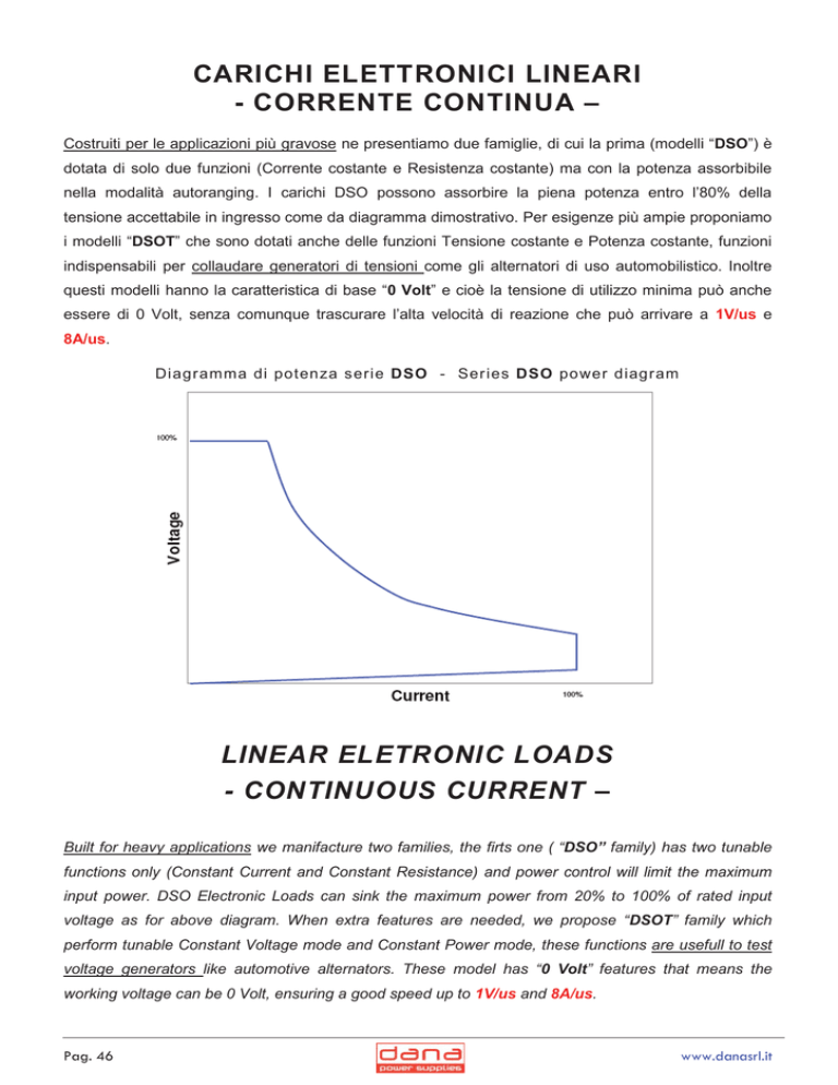
nella modalità autoranging. I carichi DSO possono assorbire la piena potenza entro l’80% della
tensione accettabile in ingresso come da diagramma dimostrativo. Per esigenze più ampie proponiamo
i modelli “DSOT” che sono dotati anche delle funzioni Tensione costante e Potenza costante, funzioni
indispensabili per collaudare generatori di tensioni come gli alternatori di uso automobilistico. Inoltre
questi modelli hanno la caratteristica di base “0 Volt” e cioè la tensione di utilizzo minima può anche
essere di 0 Volt, senza comunque trascurare l’alta velocità di reazione che può arrivare a 1V/us e
8A/us.
Diagramma di potenza serie DSO - Ser ies DSO power diagram
LINEAR ELETRONIC LOADS
- CONTINUOUS CURRENT –
Built for heavy applications we manifacture two families, the firts one ( “DSO” family) has two tunable
functions only (Constant Current and Constant Resistance) and power control will limit the maximum
input power. DSO Electronic Loads can sink the maximum power from 20% to 100% of rated input
voltage as for above diagram. When extra features are needed, we propose “DSOT” family which
perform tunable Constant Voltage mode and Constant Power mode, these functions are usefull to test
voltage generators like automotive alternators. These model has “0 Volt” features that means the
working voltage can be 0 Volt, ensuring a good speed up to 1V/us and 8A/us.
Pag. 46
www.danasrl.it
Carichi elettronici
“0 Volt”
CARATTERISTICHE TECNICHE
Electronic Load
TECHNICAL FEATURES
Tensione di alimentazione
115 ot 230 Vac ±10% 50-60 Hz
Mains input
115 or 230 Vac ±10% 50-60 Hz
Corrente – Resistenza – Potenza – Tensione
Regolabili tra “0” e il massimo valore di targa
Current – Resistence – Power – Voltage
adjustable from “0” to max rated value
Regolazione per I costante
migliore di 100 ppm
Regulation for constant I
better than 100 ppm
Regolazione per R costante
migliore di 100 ppm
Regulation for constant R
better than 100 ppm
Regolazione per P costante
migliore di 100 ppm
Regulation for constant P
better than 100 ppm
Regolazione per V costante
migliore di 50 ppm
Regulation for constant V
better than 50 ppm
Tempo di reazione
migliore di 1 V / Ps e 8 A / Ps
Reaction Time
better than 1 V / Ps and 8 A / Ps
Programmazione remota e feed-back (GPAC)
Tensioni analogiche 0-10Vdc optoisolate
Linearità minore di 0,3%
Deriva termica 1,5mV/°C
Remote programming and feed-back (GPAC)
Opto-insulated analog signal 0-10Vdc
Linearity better than 0.3%
Drift better than 1.5mV/°C
Stabilità
Dopo 20 minuti di preriscaldamento migliore di 50 ppm per
24 h a 25°C di temperatura ambiente
Stability
Better than 50 ppm over 24 h at 25°C, after 20 minutes
warm up
Coefficiente di temperatura
Migliore di 50 ppm / °C
Temperature coefficient
better than 50 ppm/°C
Temperatura ambiente
di lavoro 0÷40°C
di magazzinamento -10÷50°C
Ambient temperature
work 0÷40°C
storage -10÷50°C
Raffreddamento
ventilazione forzata
Cooling
forced ventilation
Garanzia anni
Ed. 07/2014
Years Warranty
Pag. 49
CONTROLLI SUL PANNELLO FRONTALE
FRONT PANEL CONTROLS
Power
accende e spegne l’apparecchio
Power
switches ON and OFF the device
Stand-by
interruttore per l’abilitazione dell’apparecchio a svolgere le
funzioni di cui è dotato.
Stand-by
switch that enables the device to carry out the functions
wich armed.
Function
V - R - A - P interruttori a slitta per abilitare l’apparecchio a
lavorare nelle funzioni scelte ( funzioni V e P opzionali).
Function
V - R - A - P slide switches to enable the device to carry
out the select functions ( functions V and P are optional).
GPAC - GPIB / RS
interruttore a slitta per selezionare il tipo di interfaccia che
si vuole utilizzare per la programmazione remota. GPAC,
programmazione analogica con 0 - 10 Vdc e feedback di
ritorno 0 - 10 Vdc. GPIB (opzione), programmazione
attraverso un’interfaccia IEEE488 - RS232/485.
GPAC - GPIB / RS
slide switches to select the interface used for remote
programming. GPAC, analogic programming between 0 10 Vdc and feedback 0 - 10 Vdc. GPIB (option),
programming by an interface IEEE488 - RS232/485.
Remote controls
V - R - A - P interruttori a slitta per selezionare il modo di
programmazione delle funzioni in modo locale o remoto.
Remote controls
V - R - A - P slide switches to set programming mode of
functions in local o remote mode.
Check
pulsante per la taratura delle funzioni con apparecchio in
stand-by, utilizzabile anche con programmazione remota.
Check
push button to setting the functions when the device is in
stand-by, suitable also with remote programming.
GND
boccola di terra
GND
ground connector
+/boccole di ingresso ripetute sul pannello retro.
+/input plugs available also on back panel.
Sezione Vin (opzionale)
potenziometro a 10 giri per la taratura della tensione di
ingresso. Indicatore digitale della tensione di ingresso
(tolleranza ±1,5%)
Section Vin (optional)
10 turns potentiometer to calibrate the input chosen work
voltage. Voltage input digital display (with accuracy
±1,5%)
Sezione R
potenziometro a 10 giri per la taratura della resistenza con
la quale si vuol lavorare. Indicatore digitale della resistenza
di lavoro (tolleranza ±1,5%)
Section R
10 turns potentiometer to calibrate the chosen work
resistance. Work resistance digital display (with accuracy
±1,5%)
Sezione A
potenziometro a 10 giri per la taratura della corrente da
assorbire. Indicatore digitale della corrente di lavoro
(tolleranza ±1,5%)
Section A
10 turns potentiometer to calibrate the input chosen work
current. Work current digital display (with accuracy ±1,5%)
Sezione P (opzionale)
potenziometro a 10 giri per la taratura della potenza
massima di assorbimento. Indicatore digitale della potenza
di lavoro (tolleranza ±1,5%)
Section P (optional)
10 turns potentiometer to calibrate max input chosen work
power. Work power digital display (with accuracy ±1,5%)
APP
Allarme di inversione polarità dei cavi d’ingresso con
immediata inibizione dell’apparecchio e segnalazione
luminosa.
APP
alarm LED of inversion polarity of power cables with
immediately inhibits of device.
OVP
Allarme di sovratensione in ingresso con immediata
inibizione dell’apparecchio e segnalazione luminosa.
OT
allarme di alta temperatura sul circuito di potenza che
mette il carico elettronico in stand-by con immediata
segnalazione luminosa
Pag. 50
OVP
alarm LED that indicates the overcoming of maximum
voltage work admitted on input.
Its intervention inhibits the device.
OT
alarm LED for over temperature on the power section, its
intervention inhibit the device
www.danasrl.it
CONTROLLI SUL PANNELLO POSTERIORE
BACK-PANEL CONTROLS
GPAC
Connettore “General Purpose Analgical Control” per
programmare il carico in modo remoto attraverso una
tensione analogica 0 - 10 Vdc per tutte le sue funzioni e per
la lettura dei feed-back (0 - 10 Vdc)
GPAC
“General Purpose Analogical Control” connector to be
used to control electronic load adjustements with 0 - 10
Vdc analogic voltage for all remote functions and to read
all functions feed-back
GPIB/RS (opzione)
Connettori per interfaccia di programmazione IEEE488 e
RS232/485
GPIB/RS (option)
Connectors to programme
RS232/485
+/boccole di ingresso in parallelo a quelle del pannello
frontale
+/input plugs available also on the front panel
interface
IEEE488
and
OPZIONI
OPTIONS
PS
interfaccia per programmare il carico elettronico con
standard IEEE488/RS232
PS
interface to program electronic load with standard
IEEE488/RS232
PW
interfaccia per programmare il carico elettronico con
standard IEEE488/RS485
PW
interface to program electronic load with standard
IEEE488/RS485
V
opzione per far lavorare il carico con la funzione di modo
“tensione costante”
V
option in order to work the load also in “constant voltage”
mode
P
opzione per far lavorare il carico con la funzione di modo
“potenza costante”
P
option in order to work the load also in “constant power”
mode
I modelli in
tabella sono
fornibili con
tensione e
corrente di
ingresso
secondo
esigenza
Watt
Mod
Vin DC
Iin
500
DSOTB
0 ÷ 600
0 ÷ 20
Rack 3 U
800
DSOTM
0 ÷ 600
0 ÷ 40
Rack 3 U
1200
DSOTS
0 ÷ 600
0 ÷ 60
Rack 4 U
1600
DSOTP
0 ÷ 800
0 ÷ 100
Rack 4 U
2400
DSOTR
0 ÷ 800
0 ÷ 150
Rack 6 U
3200
DSOTG
0 ÷ 800
0 ÷ 200
Rack 9 U
4000
DSOTT
0 ÷ 800
0 ÷ 250
Rack 12 U
DSOTX
0 ÷ 800
0 ÷ 250
Rack 42 U
ORDER EXAMPLE
..........
-
-.......-
V in
I in
The models in
the table are
available with
voltage and
input current
on customer
request
...30kW
ESEMPIO D’ORDINE
Mod
Case
Watt
opzioni
..........
-
-.......-
Mod
V in
I in
Watt
option
Esempio: 4.000 W / 0-16 Vdc / 0-250 A / opzione RS232
Example: 4.000 W / 0-16 Vdc / 0-250 A / option RS232
DSOTT 16-250-4000 - PS4
DSOTT 16-250-4000 - PS4
Ed. 07/2014
Pag. 51

