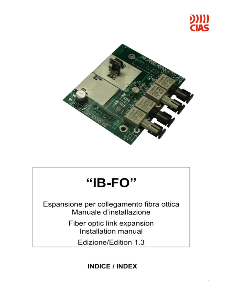
“IB-FO”
Espansione per collegamento fibra ottica
Manuale d’installazione
Fiber optic link expansion
Installation manual
Edizione/Edition 1.3
INDICE / INDEX
.
CIAS Elettronica S.r.l.
1.
1.
2.
3.
4.
1.
1.
2.
3.
4.
Ed. 1.3
DESCRIZIONE ........................................................................................................................................... 2
1 Generalità ..........................................................................................................................................2
Installazione ................................................................................................................................................ 2
Taratura ...................................................................................................................................................... 3
Caratteristiche tecniche .............................................................................................................................. 3
DESCRIPTION ........................................................................................................................................... 4
1 General information ...........................................................................................................................4
Installation................................................................................................................................................... 4
Setting......................................................................................................................................................... 5
Technical characteristics ............................................................................................................................ 5
Manuale di Installazione
Pagina 1 di 4
IB-FO
CIAS Elettronica S.r.l.
Ed. 1.3
1. DESCRIZIONE
Espansione per collegamento in fibra ottica “IB-FO”
1. 1 Generalità
L’espansione IB-FO permette di collegare fino a due canali bidirezionali in fibra ottica ad un IBHUB e/o FMC-Rep, permettendo quindi il collegamento delle barriere e dei dispositivi di campo
attraverso la fibra invece del cavo in rame.
2. Installazione
L’espansione IB-FO deve essere montata sul retro del rack IB-System sui connettori OPTO1
e OPTO2. Può essere orientata indifferentemente verso l’alto o verso il basso. IB-FO può
essere montata anche all’interno di FMC-Rep (vedere figura) allo scopo di formare FMC-Rep
FO.
L’installazione di IB-FO non richiede alcuna modifica della configurazione del sistema, e non
esclude l’utilizzo delle preesistenti linee di collegamento in rame.
Manuale di Installazione
Pagina 2 di 4
IB-FO
CIAS Elettronica S.r.l.
Ed. 1.3
3. Taratura
La potenza nominale di IB-FO permette di raggiungere una distanza di circa 4,5Km utilizzando
una fibra 62.5/125µm. Se il collegamento in fibra ottica fosse maggiore di 2 Km è consigliabile
aumentare la potenza in uscita cortocircuitando i ponticelli J1 e J2 evidenziati in figura,
mediante una goccia di stagno.
4. Caratteristiche tecniche
Alimentazione
Connettori Ottici tipo:ST
Lunghezza d’onda
Fibra ottica Multimodale
Corrente assorbita
Power budget ottico con Fibra
62.5/125µm
Temperatura di funzionamento
Min.
9V
.
-25 °C
Typ.
13.8 V
Max.
16 V
850nm
62.5/125µm
28 mA
12.0 dB
40 mA
14.0 dB
+60 °C
‘
Manuale di Installazione
Pagina 3 di 4
IB-FO
CIAS Elettronica S.r.l.
Ed. 1.3
1. DESCRIPTION
Fiber optic adaptor “IB-FO”
1. 1 General information
The IB-FO adaptor allows to use up to two bidirectional optical channel to an IB-HUB and/or
FMC-Rep, allowing, therefore, to connect barriers and field devices through fiber optic instead
of copper cable.
2. Installation
IB-FO adaptor can be mounted on the rear panel of the IB-System-R, on OPTO1 and
OPTO2 connectors. It can be oriented towards the top or the bottom indifferently. IB-FO can
be combined also, with FMC-Rep (see figure) to form FMC-Rep FO.
The installation of IB-FO doesn’t need any change in system configuration and doesn’t
exclude the possibility to use old copper lines.
Installation handbook
Pagina 4 di 4
IB-FO
CIAS Elettronica S.r.l.
Ed. 1.3
3. Setting
The nominal power of IB-FO allows a link up to approximately 4,5Km using a 62.5/125µm
Multimodal fiber optic. If the link length is more than 2 Km it is advisable to increase the optical
output power shorting J1 and J2 jumpers, by a tin drop.
4. Technical characteristics
Supply voltage
Optical Connectors: ST type
Wavelength
Multimodal Fiber Optic
Current consumption
Optical Power budget with fiber optic
62.5/125µm
Working temperature
Installation handbook
Min.
9V
.
-25 °C
Pagina 5 di 4
Typ.
13.8 V
Max.
16 V
850nm
62.5/125µm
28 mA
12.0 dB
40 mA
14.0 dB
+60 °C
IB-FO
NOTE:
Con la presente, CIAS Elettronica, dichiara che questo rivelatore di intrusione “ IB-FO ” è conforme ai requisiti
essenziali ed alle altre disposizioni rilevanti della Direttiva 1999/5/CE (Art.3.1a-3.1b-3.2)
Hereby, CIAS Elettronica, declares that this movement detector “ IB-FO ” is in compliance with the essential
requirement and other relevant provisions of Directive 1999/5/EC (Art.3.1a-3.1b-3.2)
Questo apparecchio è contrassegnato in conformità alla Direttiva Europea 2002/96/EC, Waste Electrical and
Electronic Equipment (WEEE)
Assicurarandosi che questo prodotto sia smaltito in modo corretto, l’utente contribuisce a prevenire le potenziali
conseguenze negative per l’ambiente e la salute.
sul prodotto o sulla documentazione d’accompagnamento indica che questo prodotto non deve
Il simbolo
essere trattato come rifiuto domestico ma deve essere consegnato presso l’idoneo punto di raccolta per il riciclaggio
d’apparecchiature elettriche ed elettroniche.
Disfarsene seguendo le normative locali per lo smaltimento rifiuti.
Lo smaltimento abusivo è punito con le sanzioni previste dalla legislazione nazionale vigente
Il prodotto può essere riconsegnato al distributore/installatore a fine vita in occasione di un nuovo acquisto.
This product is marked in compliance with the European Directive 2002/96/EC, Waste Electrical and Electronic
Equipment (WEEE).
The correct disposal of the product will prevent potential negative consequences for the environment and the human
health.
on the product or into the annexed documentation indicates that this product does not have to be
The symbol
dealt like domestic refusal but must be delivered near the suitable point of collection for the recycling of electrical and
electronic equipment.
The illicit disposal will be endorsed according to local l regulations.
At the end of operative life the product can be given back to the vendor/installation organization in occasion of a new
purchase.
Copyright CIAS Elettronica S.r.l.
Stampato in Italia / Printed in Italy
CIAS Elettronica S.r.l.
Direzione, Ufficio Amministrativo, Ufficio Commerciale, Laboratorio di Ricerca e Sviluppo
Direction, Administrative Office, Sales Office, Laboratory of Research and Development
20158 Milano, via Durando n. 38
Tel. +39 02 376716.1
Fax +39 02 39311225
Web-site: www.cias.it
E-mail: [email protected]
Stabilimento / Factory
23887 Olgiate Molgora (LC), Via Don Sturzo n. 17

