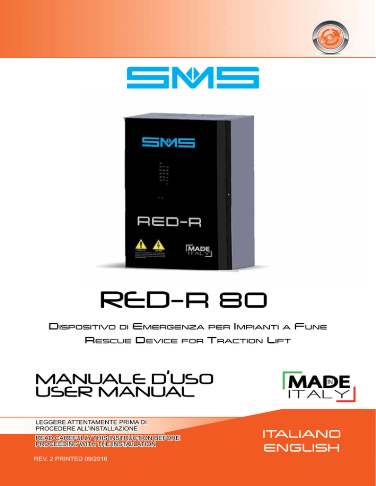
RED-R 80
Dispositivo di Emergenza per Impianti a Fune
Rescue Device for Traction Lift
MANUALE D’USO
USER MANUAL
LEGGERE ATTENTAMENTE PRIMA DI
PROCEDERE ALL’INSTALLAZIONE
READ CAREFULLY THIS INSTRUCTION BEFORE
PROCEEDING WITH THE INSTALLATION
REV. 2 PRINTED 09/2016
ITALIANO
ENGLISH
RED-R 80
INDICE / INDEX
Sicurezza
Dimensioni e Fissaggi
Schema Collegamenti
Disposizione componenti
Dati Tecnici
Caratteristiche Tecniche - Principio di funzionamento Predisposizioni di
Fabbrica
Collegamento Batterie
Installazione
Messa in Marcia
Prove di Isolamento
Regolazioni
Impostazione scheda REDR
Regolazioni e Segnalazioni Inverter di Potenza
Regolazioni e Segnalazioni scheda REDR
Collegamenti opzionali per comando marcia di emergenza verso un
piano di evacuazione prefissato
Controlli e Manutenzioni -Schede Accessorie - Lista Prti di Ricambio
Risoluzione Problemi
Schemi di Collegamento Interni
Dichiarazione di conformita’
Safety
Dimension and Fastening
Wiring Diagram
Layout
Technical Data
Technical Specifications - Working Cycle - Factory Setting
Batteries Connection
Installation
Commissioning
Insulation Test Instructions
Adjustments
REDR Board Setting
Power Inverter PWM
REDR Board Adjustments and Signals
Connections for emergency Rescue Operation to a defined evacuation floor
Check and Maintenance - Optional Board - Spare Part List
Troubleshooting
Internal Connection Drawing
Declaration of conformity
2
Pag. 03
Pag. 04
Pag. 05
Pag. 06
Pag. 07
Pag. 08
Pag. 09
Pag. 10
Pag. 12
Pag. 13
Pag. 14
Pag. 15
Pag. 16
Pag. 17
Pag. 18
Pag. 20
Pag. 21
Pag. 34
Pag. 35
Pag. 03
Pag. 04
Pag. 05
Pag. 22
Pag. 23
Pag. 24
Pag. 25
Pag. 26
Pag. 28
Pag. 29
Pag. 30
Pag. 31
Pag. 32
Pag. 33
Pag. 34
Pag. 32
Pag. 33
Pag. 34
Pag. 35
PRINTED 09/2016 REV.2
RED-R 80
Sicurezza / Safety
SICUREZZA
ITALIANO
SAFETY
L’involucro metallico del dispositivo ha bordi taglienti,
maneggiarlo con attenzione utilizzando guanti idonei
allo scopo.
The metallic case of the device has sharp edges. Handle it
with care using suitable gloves for the purpose.
Il dispositivo ha un peso notevole. Sollevarlo da terra
con mezzi adeguati per evitare problemi alla propria
salute.
The device has a considerable weight. Lift it from the
ground with appropriate means to avoid problems with
your health.
Il dispositivo ha un peso notevole. Una volta sollevato
da terra fare attenzione in fase di appoggio o di fissaggio
ad una parete.
The device has a considerable weight. Be careful once it
has been lifted from the ground in supporting or fixing to
a wall.
Se il dispositivo è visibilmente danneggiato, se
mancano componenti, o se la taglia del dispositivo
non è adeguata a quella dell’impianto, NON procedere
assolutamente all’installazione.
If the device is clearly damaged, missing parts, or the size
of the device is not correct for the lift, absolutely do NOT
proceed with the installation.
L’installazione, il controllo e la manutenzione del
dispositivo devono essere effettuate esclusivamente
da
personale
qualificato
e
devono
essere
eseguite solo quando è isolato dalle sorgenti di
alimentazione. Un’installazione errata può causare
il malfunzionamento dell’apparecchiatura, lesioni o
anche la morte. Seguire scrupolosamente le norme di
sicurezza vigenti.
The installation, control and maintenance of the device
must be carried out only by qualified personnel and only
when the power supply is disconnected.
Improper installation can cause equipment malfunction,
injury, or even death. Carefully follow the safety directives.
Prima di effettuare qualsiasi collegamento, assicurarsi
che il quadro di manovra sia privo di alimentazione
e che l’interruttore IE del dispositivo sia disattivo.
Evitare che qualsiasi tipo di oggetto esterno entri nel
dispositivo in quanto può portare al malfunzionamento
dello stesso o a condizioni di pericolo al momento
della connessione alla rete elettrica.
Before making any connections, make sure that the
control panel is not supplied and that the IE switch the
device is off. Avoid any kind of external object enters the
device as it can lead to the failure of the or hazardous
conditions at the time of connection to the mains.
Collegare la terra del dispositivo alla terra dell’impianto
per la protezione dai contatti indiretti, secondo le
normative vigenti. Proteggere adeguatamente tutti i
collegamenti per evitare contatti accidentali.
Connect the ground of the device to the installation ground
for the protection against indirect contact, according to
the safety directives. Properly protect all connections to
prevent accidental contact.
Per garantire il corretto funzionamento del dispositivo
e per non incorrere in rischi di incendio, utilizzare cavi
di sezione adeguata in funzione della corrente e della
lunghezza del collegamento.
Dopo avere messo in funzione e provato il dispositivo,
rimuovere l’eventuale ponte fatto sul 4° polo per
garantire il corretto funzionamento in caso di apertura
manuale dell’interruttore generale. Chiudere l’involucro
metallico per evitare contatti accidentali.
Il dispositivo funziona a batterie, fornite da SMS su
richiesta. Assicurarsi di utilizzare batterie adeguate
al dispositivo e alla corrente di carica indicata, per
evitare rischi di esplosione dovuti alla liberazione di
idrogeno. Non invertire la polarità delle batterie, né
cortocircuitarle.
Consultare la documentazione fornita dal costruttore
delle batterie.
Gli esempi e gli schemi elettrici di questo manuale
sono inseriti solo in forma esplicativa. Il contenuto
del presente manuale è soggetto a revisioni senza
preavviso. In nessun caso SMS accetterà reclami per
danni diretti o indiretti in seguito all’uso o installazione del dispositivo.
PRINTED 09/2016 REV.2
Ø
To ensure the proper functioning of the device and in
order to avoid risks of fire, use cables of suitable section in
function of the currents involved and considering the cable
length required for installation.
After put into operation and tested the device, remove the
bridge made on the 4th pole to ensure proper operation in
case of opening of the main power switch. Close the metal
casing of the device to prevent accidental contact.
The device is battery operated, not normally provided by
SMS. Be sure to use batteries appropriate to the device
and to the charging current indicated to avoid the risk of
explosion due to the release of hydrogen.
Do not reverse the polarity of the batteries or short circuit.
Consult the documentation provided by the battery
manufacturer.
The examples and diagrams in this manual are included only for illustrative purposes.
The contents of this manual are subject to change
without notice. In no event will accept the liability for
damages, indirect or consequential damages resulting from the use or application of the device.
3
Dimensioni e Caratteristiche tecniche / Dimension and Technical Specifications
RED-R 80
DIMENSIONI E FISSAGGI / DIMENSION AND FASTENING
H
310
DEVICE / CODE
WIDTH (mm) HEIGHT (mm) DEPTH (mm)
RED-R 80
SUGGESTED
BATTERIES
386
NOMINAL CAPACITY
RED-R 80 STANDARD
570
NOMINAL CAPACITY
RED-R 80F
(FORCED DIRECTION)
250
MAX INTERNAL
RESISTANCE
WEIGHT (kg)
without batteries
23
MIN. DISCARGE
COSTANT CURRENT
(5min @ 9,6Vdc)
CORRENTE
BATTERIE CAPACITA’ NOMINALE CAPACITA’ NOMINALE
MASSIMA
DI SCARICA
SUGGERITE RED-R 80 STANDARD
RED-R80F
RESISTENZA INTERNA MINIMA
(5min
@
9,6Vdc)
(MARCIA FORZATA)
4X12Ah
18mΩ
42A
4X18Ah
8X18Ah
12mΩ
63A
4X26Ah
8X26Ah
11mΩ
105A
4X40Ah
8X40Ah
7mΩ
178A
TYPE BATTERY : SEALED LEAD ACID BATTERY
TIPO DI BATTERIE: AL PIOMBO
4
PRINTED 09/2016 REV.2
Schema Collegamenti
RED-R 80
ITALIANO
SCHEMA COLLEGAMENTI / WIRING DIAGRAM
PRINTED 09/2016 REV.2
5
RED-R 80
Disposizione componenti
DISPOSIZIONE COMPONENTI
ALLOGGIO SCHEDE
OPZIONALI
TRASFORMATORI
ELEVATORI T1-T2
INVERTER
MOTORE
PWM0802
MORSETTIERA
INTERRUTTORE
GENERALE IE
SCHEDA DI CONTROLLO
E INVERTER AUSILIARIO
6
CONTATTORI MOTORE
PRINTED 09/2016 REV.2
RED-R 80
ITALIANO
Dati Tecnici
DATI TECNICI
Corrente Nominale Motore
Temperatura di stoccaggio
RED-R 80
STANDARD
RED-R
PER MSMP
RED-R 32F
CON SENSO DI
MARCIA
FORZATO
7A a 60A
7A a 42A
7A a 32A
-0°C
40°C umidità 95%
INVERTER DI POTENZA PWM
Tensione Batterie Ammesse
24-48-72-96 Vdc (Vb).
96Vdc (Vb)
Tensione di uscita trifase
Regolabile circa dal 30% al 60% di Vb , Vac
Frequenza di uscita
0.5 ÷ 5 Hz oppure 1 ÷ 10 Hz
Corrente massima di picco in
uscita
85A
PTC per protezione corto circuito delle uscite OUP ed
ODN per controllo senso di marcia
Protezioni Hardware
Limite di corrente (picco) assorbita da batterie
Sovraccarico inverter
Controllo tensione batterie Vb : Scariche a Vb -25% ,
sovraccariche a Vb +25%
Controllo di corrente minima sul motore
Controllo di corrente rigenerata verso le batterie
Controllo di presenza tensione su circuito del freno
Protezioni software
CARICA BATTERIE
Tensione di alimentazione
Tensione di uscite
1~230Vac 50/60 Hz +8/-15%
54Vdc con carico 0%
Corrente di carica massima
108Vdc con
carico 0%
2,5A
INVERTER AUSILIARIO TRIFASE
Tensione di uscita
3x36Vac
Corrente di Uscita
15A
Massima potenza prelevabile
600VA
PRINTED 09/2016 REV.2
7
Caratteristiche tecniche / Principio di Funzionamento / Predisposizione di Fabbrica
RED-R 80
CARATTERISTICHE TECNICHE
Ogni volta che si verifica una mancanza di energia (black-out) nell’impianto, il dispositivo interviene
automaticamente in pochi secondi, prendendo il controllo dei comandi dell’ascensore.
Verifica l’efficienza delle sicurezze e utilizzando le batterie di cui è provvisto, fornisce
un’alimentazione ausiliaria ai vari circuiti (motore, freno, porte, etc) consentendo il movimento
della cabina a velocità ridotta fino al piano più vicino nel senso favorevole di marcia (modello
RED-R 32F procede nella direzione scelta) , ed apre le porte.
IS,FS,ISQ,M- SAFETY CHAIN CONTROL
F+/F-,FQ+/FQ- BRAKE CONTROL
MP1,2,3MP1Q,2Q,3Q,AP,CH DOOR MOTOR CONTROL
U,V,W MOTOR CONTROL
Z1/Z2 RESCUE OPERATION END
PRINCIPIO DI FUNZIONAMENTO
RED-R entra in funzione quando si verifica la mancanza della tensione di rete, anche di una sola
fase, ed il 4° polo e’ chiuso.
Trascorsi 4-5 secondi, si accende il Led B e inizia il ciclo di emergenza, che viene comunque
portato a termine anche se ritorna l’alimentazione da rete.
Vengono isolati i circuiti del quadro di manovra relativi al freno, serie sicurezze, motore porte, ecc.,
quindi l’inverter ausiliario alimenta i due trasformatori T1 e T2.
Il ciclo di emergenza prosegue in modo diverso in funzione della posizione della cabina:
Con cabina al piano, RED-R comanda l’apertura delle porte. Trascorso il tempo di apertura, tarabile
col trimmer P, RED-R si arresta ed è pronto per un nuovo ciclo d’emergenza.
Con cabina fuori piano, RED-R controlla lo stato delle sicurezze. Se la serie delle sicurezze risulta
aperta, comanda la chiusura delle porte per un tempo massimo di 20 secondi. Quando la serie
delle sicurezze risulta chiusa, è abilitata l’attivazione dei contattori TP1 e TP2.
Successivamente, viene azionato l’inverter di potenza per la movimentazione della cabina.
Se modello RED-R 80: Vengono eseguiti 2 test per verificare la direzione di marcia che richiede
meno energia.
Se modello RED-R 32F: procede nella direzione scelta.
Il movimento della cabina prosegue fino al primo piano che incontra e, dopo il ritardo di fermata
(tarabile col trimmer R), la cabina si arresta, cadono i contattori di marcia e si aprono le porte.
Trascorso il tempo di apertura porte, RED-R di arresta ed è pronto per un nuovo ciclo d’emergenza.
PREDISPOSIZIONE DI FABBRICA
RED-R viene consegnato con le seguenti predisposizioni:
• Tensione bobina FRENO 48/60Vdc , per tensioni diverse e’ necessario spostare la connessione
BRAKE sul trasformatore T1 dal morsetto 70 al morsetto voluto.
• Operatore porte trifase 125Vac. Per tensioni diverse e’ necessario spostare le connessioni
DOOR1 e DOOR2 sui trasformatori T1 e T2 dal morsetto 125 al morsetto voluto.
In caso di Operatore porte MONOFASE oppure TRIFASE comandato da REGOLATORE VVVF,
e’ necessario spostare il connettore volante connesso a 3P su VF (vedi Pag. 15). In questa
configurazione è disponibile una tensione d’alimentazione di 230Vac su MP1 – MP2.
• Tensione di manovra AC, per tensione di manovra DC e’ necessario spostare il connettore
volante connesso ad AC su DC (vedi Pag. 15).
8
PRINTED 09/2016 REV.2
Collegamento Batterie
RED-R 80
ITALIANO
COLLEGAMENTO BATTERIE
COLLEGARE L’ALIMENTAZIONE 1~230V 50/60HZ
PER IL CARICA BATTERIE AI MORSETTI F-N.
COLLEGARE LE 4 BATTERIE IN SERIE COME INDICATO NEL DISEGNO SEGUENTE
Modello RED-R 80:
B+
B-
Modello RED-R 32F:
BT1BT5-
BT4+
BT8+
VERIFICARE SULLO SPORTELLO IL LED BI, SE RISULTA ACCESO, LE BATTERIE SONO COLLEGATE CON
POLARITA’ INVERTITA: CORREGGERE IL COLLEGAMENTO E VERIFICARE IL FUSIBILE F1, SE NECESSARIO
SOSTITUIRLO.
PRINTED 09/2016 REV.2
9
Installazione
RED-R 80
INSTALLAZIONE
COLLEGARE I MORSETTI L1-L2-L3-PE IN PARALLELO ALL’ALIMENTAZIONE TRIFASE
DEL QUADRO DI MANOVRA (3~230/400V 50/60HZ)
COLLEGARE I MORSETTI S1-S2 AL 4° POLO DELL’INTERRUTTORE GENERALE F.M.
NEL LOCALE MACCHINE.
Se il 4° polo è aperto, l’emergenza non è abilitata al funzionamento.
questo ingresso può essere utilizzato per disabilitare l’emergenza in
condizioni particolari come, ad esempio, manovra di ispezione o manovra
pompieri (in tal caso, collegare in serie al 4° polo contatti puliti che risultino
aperti durante tali manovre).
COLLEGARE I
MORSETTI
U-V-W-PE
AL MOTORE (IN CASO DI MOTORI A 2
VELOCITÀ, ALL’AVVOLGIMENTO DI ALTA),
IN
PARALLELO AL COLLEGAMENTO
ESISTENTE.
INTERROMPERE L’ALIMENTAZIONE PER L’ELETTROMAGNETE DEL FRENO,
COLLEGANDO LA LINEA PROVENIENTE DAL QUADRO AI MORSETTI FQ+–FQ- E
L’ELETTROMAGNETE DEL FRENO AI MORSETTI F+–F-. RISPETTARE LE POLARITÀ.
10
PRINTED 09/2016 REV.2
ITALIANO
RED-R 80
COLLEGARE IL MOTORE PORTE COME SEGUE:
SE MOTORE PORTE TRIFASE
(FUNZIONAMENTO DIRETTO)
INTERROMPERE L’ALIMENTAZIONE
PER
IL
MOTORE
PORTE,
COLLEGANDO
LA
LINEA
PROVENIENTE DAL QUADRO AI
MORSETTI MPQ1-MPQ2-MPQ3 ED IL
MOTORE PORTE AI MORSETTI MP1MP2-MP3.
SE MOTORE PORTE MONOFASE
O TRIFASE CONTROLLATO DA
REGOLATORE VVVF
SPOSTARE
IL
CONNETTORE
VOLANTE CONNESSO A 3P SU VF
INTERROMPERE L’ALIMENTAZIONE
PER IL MOTORE PORTE, COLLEGANDO
LA
LINEA
PROVENIENTE
DAL
QUADRO AI MORSETTI MPQ1-MPQ2
E L’ALIMENTAZIONE PER IL MOTORE
O IL REGOLATORE VVVF AI MORSETTI
MP1-MP2.
COLLEGARE
IN
PARALLELO
AI
COMANDI DEL REGOLATORE DELLE
PORTE I SEGUENTI MORSETTI: MP3
AL COMUNE DEI COMANDI, MP4 AL
COMANDO DI APERTURA PORTE ED
MP5 AL COMANDO DI CHIUSURA
PORTE.
INTERROMPERE L’INIZIO DELLA
CATENA DELLE SICUREZZE
COLLEGANDO LA LINEA CHE VIENE DAL
VANO AL MORSETTO IS E LA LINEA
CHE VIENE DAL QUADRO AL MORSETTO
ISQ.
INTERROMPERE LA FINE DELLA
CATENA DELLE SICUREZZE
COLLEGANDO LA LINEA CHE VIENE DAL
VANO AL MORSETTO FS E LA LINEA
CHE VIENE DAL QUADRO AL MORSETTO
FSQ.
COLLEGARE IL MORSETTO M- ALLA TERRA DEL QUADRO DI MANOVRA.
COLLEGARE I MORSETTI Z1-Z2 ALL’IMPULSORE DI FERMATA IN EMERGENZA.
RED-R NON PREVEDE UN’USCITA SPECIFICA PER LA SEGNALAZIONE “EMERGENZA IN CORSO”; SE
NECESSARIO, COLLEGARE IL SEGNALE LUMINOSO AL SECONDARIO 0-24 DEL TRASFORMATORE T1
OPPURE T2: QUI È DISPONIBILE UNA TENSIONE 24VAC PER TUTTO IL CICLO DI EMERGENZA.
PRINTED 09/2016 REV.2
11
Installazione / Messa in Marcia
RED-R 80
MESSA IN MARCIA
PORRE IN OFF
L’INTERRUTTORE
GENERALE
DELL’IMPIANTO
VERIFICARE CHE
IL COLLEGAMENTI
SIANO CORRETTI
OFF
RED-R 80:
>48V - <54V
RED-R 32F:
>96V - <108V
CONTROLLARE LO
STATO DI CARICA
DELLE BATTERIE:
- TOGLIERE
TEMPORANEAMENTE
IL CONNETTORE
CN12 E MISURARE
LA TENSIONE DELLE
BATTERIE IN SERIE:
RED-R 80: Dato per n. 4
Batterie.
RED-R 32F: Dato per n.
8 batterie
PORRE IN ON
L’INTERRUTTORE
GENERALE
DELL’IMPIANTO
ON
CONTROLLARE FUNZIONAMENTO
ALL’APERTURA DEI CONTATTI
DELLA SERIE DI SICUREZZA.
VERIFICARE CHE SULLA SCHEDA
RED-R SIANO ACCESI I SEGUENTI
LEDS:
- RS-ST PRESENZA
ALIMENTAZIONE TRIFASE
- 4P
4° POLO CHIUSO
- A
SCHEDA PRONTA PER
MANOVRA EMERGENZA
PORRE IN OFF
L’INTERRUTTORE GENERALE
LUCE
OFF
12
PRINTED 09/2016 REV.2
RED-R 80
Messa in Marcia / prove isolamento
ITALIANO
PROVARE ORA IL FUNZIONAMENTO IN EMERGENZA, PROCEDENDO NEL MODO
SEGUENTE:
- TOGLIERE LA FORZA MOTRICE APRENDO IL RELATIVO INTERRUTTORE GENERALE, CON IMPIANTO FUORI PIANO.
- ESEGUIRE UN PONTE FRA I MORSETTI S1 – S2, ALTRIMENTI CON IL 4° POLO APERTO L’IMPIANTO NON PUÒ ANDARE IN EMERGENZA.
DOPO ALCUNI SECONDI INIZIA LA MANOVRA DI EMERGENZA, CON LE MODALITÀ
DESCRITTE NEL PRECEDENTE PARAGRAFO PRINCIPIO DI FUNZIONAMENTO
PROVE DI ISOLAMENTO
PORRE IN OFF L’INTERRUTTORE
IE DEL RED-R
OFF
SCOLLEGARE IL FILO M- DAL QUADRO DI MANOVRA
NELLE CONDIZIONI IN CUI SI PROVA L’ISOLAMENTO DEI VARI CIRCUITI DEL
QUADRO DI MANOVRA, CONTROLLARE
L’ISOLAMENTO DEI CIRCUITI DI RED-R RISPETTO A TERRA E AGLI ALTRI CIRCUITI
SUI MORSETTI:
• A1 SUL CONTATTORE TP1
• 125 SUI TRASFORMATORI T1 E T2
• 220 SUI TRASFORMATORI T1 E T2
• F ALIMENTAZIONE CARICA-BATTERIE 1~230VAC
• CONDUTTORI ROSSO/NERO AGLI ESTREMI DELLA SERIE DELLE BATTERIE (RED-R
80: 0V, 48V - RED-R 32F: BT1-, BT8+)
PRINTED 09/2016 REV.2
13
Regolazioni
RED-R 80
REGOLAZIONI
RED-R non necessita di particolari tarature. Tuttavia, al fine di adattarsi a qualunque
tipo di impianto, sono previste le seguenti regolazioni:
TRIMMER V (INVERTER PWM): TENSIONE D’USCITA AL MOTORE DI TRAZIONE
TRIMMER F (INVERTER PWM): FREQUENZA D’USCITA AL MOTORE DI TRAZIONE (DA 1 A 10Hz oppure da 0.5 A 5 Hz)
TRIMMER P: TEMPO DI
APERTURA PORTE (DA 0 A
31 SECONDI) (Pag. 17)
TRIMMER R: RITARDO
DI FERMATA (DA 0 A 5
SECONDI) (Pag. 17)
La coppia di un motore aumenta aumentando la Tensione (V) e diminuendo la Frequenza
(F). Tuttavia, tale operazione aumenta le correnti assorbite dal motore stesso, con possibile
intervento delle protezioni di sovraccarico.
Normalmente le tarature di fabbrica (V = 50% e F = 50%) garantiscono un buon funzionamento
su qualunque tipo di motore.
14
PRINTED 09/2016 REV.2
RED-R 80
ITALIANO
impostazioni scheda redr
IMPOSTAZIONI SCHEDA REDR
T2
CN1
CN4
CN2 CN3 CN5
CN6
CN7
CN8
CN9
DC
CN12
CN10
VF
AC
48
T1
CN11
SCHEDA REDR
RED-R BOARD
3P
SP3
SP4
SP2
SP1
102.06.REDR_
Tensione Alimentazione
Sicurezze
Solder
points
Impostazioni solder points
(Funzione dei contatti puliti NO-NC delle
morsettiere M1 e M2
( Un solo solder point deve essere
chiuso)
SP1
Tipo Motore Porte
Chiuso : KE1 (emergenza in corso) Impostazione di fabbrica
SP2
Chiuso : AP (apertura porte)
3P = TRIFASE
SP3
Chiuso : CH (chiusura porte)
SP4
Chiuso : PW (comando inverter potenza)
AC = ALTERNATA (Vac)
DC = RADDRIZZATA (Vdc/cr)
VF = Regolato con VVVF
DIP SWITCH SW1
1
ON : INTERR. DI FERMATA CON CONTATTO N.A.
OFF : CON CONTATTO N.C
2
ON : PORTE IN CHIUSURA FORZATA
OFF : PORTE IN CHIUSURA NORMALE
3
ON : TEMPO ATTESA EMERGENZA
OFF : TEMPO ATTESA EMERGENZA
4
ON : TEMPO ATTESA EMERGENZA
OFF : TEMPO ATTESA EMERGENZA
5
NON USATO
6
NON USATO
7
NON USATO
8
NON USATO
PRINTED 09/2016 REV.2
TEMPO ATTESA
DIP3 DIP4
}
OFF
OFF
5s
OFF
ON
10s
ON
OFF
20s
ON
ON
30s
15
Regolazioni e segnalazioni inverter di potenza pwm0802
RED-R 80
REGOLAZIONI E SEGNALAZIONI INVERTER DI POTENZA PWM802
M3
M4
M5
LEDS
DL4 : Presenza tensione freno
DL5 : Comando relè freno
DL6 : vedi ALLARMI
DL7 : vedi ALLARMI
DL8 : Alimentazione +5V
DL9 : Inverter in MARCIA
DL10 : Comando di marcia SALITA
DL11 : Comando di marcia DISCESA
DL4
DL5
DL6
DL7
DL8
DL9
DL10
DL11
M2
INVERTER PWM
SP3
R
M1
UA VA WA
Il lampeggio
intermittente di
questi 3 led indica
la presenza della
tensione di uscita
verso il motore
Se chiuso evita controllo presenza
tensione freno
REGOLAZIONI:
R: Ritardo lettura corrente da 0.5 a 3.4 secondi
I: Corrente minima di apertura freno, dal valore minimo (circa 1 A) al valore massimo del dispositivo
F: Frequenza di uscita
V: Tensione di uscita
X: Corrente DC di frenatura. Da 0 alla massima corrente
del dispositivo. Trimmer normalmente non montato.
I
F
JP5
V
X
A
B
JP1
JP3
5V
B
A
JP2
JP4
CONFIGURAZIONE TENSIONE
PWM 0802 JP1 JP2
48V A A
24V A B
72V B B
96V B A
MORSETTIERE
M1 : Uscite inverter motore UA, VA, WA
M2 : Ingresso alimentazione potenza RED-R 80: 48Vdc
RED-R 32F 96V PA (+), NA (-)
M3 : Uscita di alimentazione ventole (opzionali)
M4 : Freno – Alimentazione (B~, B~) e comando (B+, B-)
M5:
P24
RUN
UP
DN
Alimentazione logica PWM
Ingresso a 24V - Comando marcia
Ingresso a 24V - Forzatura marcia salita
Ingresso a 24V - Forzatura marcia discesa +CM
Comune comandi PWM
OUP Uscita Open Collector per segnalazione marcia salita
ODN Uscita Open Collector per segnalazione marcia discesa
ALTRI JUMPER
JP3 : MODULAZIONE SVM. POS ‘A’ = DISABILITATA, POS. ‘B’ = ABILITATA. Utilizzare per i motori asincroni, per aumentare la tensione di uscita, quindi la coppia del motore, aggiungendo la 3° armonica.
JP4 : NON TOCCARE
JP5 : NON TOCCARE
ALLARMI
Led DL6
16
Led DL7
Descrizione
Tensione di Batterie Troppo Bassa
Tensione di Batterie Troppo Alta
Mancanza tensione Freno
Corrente di Uscita Troppo Bassa
Corrente di picco in uscita Troppo Alta
Corrente media in uscita Troppo Alta
Note:
Legenda :
= Led spento
= Led acceso
= Led lampeggiante
PRINTED 09/2016 REV.2
Regolazioni e segnalazioni scheda redr
RED-R 80
ITALIANO
REGOLAZIONI E SEGNALAZIONI SCHEDA REDR
Ingressi :
SC: Ingresso catena sicurezze
4P: Ingresso 4° polo
SC
CC
RS: Presenza rete fasi R-S
4P
+5V
CH
RS
CB
AP
ST
BI
OP
ZF
A
KE
CT
B
Uscite :
CC: Comando contattori
CH: Chiusura porte
AP: Apertura porte
OP: Opzionale
KE: Scambio serie di sicurezza
ST: Presenza rete fasi S-T
ZF: Ingresso zona di fermata (Z1-Z2)
CT: Ingresso controllo contattori
+5: Alimentazione scheda
CB: Caricabatteria attivo
BI: Batterie invertite
A,B,C:
Leds di diagnostica
C
P
R
P: Ritardo apertura porte,
da 0,1 a 31 secondi
R: Ritardo di fermata,
da 0 a 5 secondi
DIAGNOSTICA
Led A
Led B
Led C
Descrizione
Non pronto per emergenza (4° Polo aperto)
Pronto per emergenza (4° Polo chiuso)
Ciclo di emergenza in corso
Ciclo di emergenza concluso
Sovracorrente inverter ausiliario
Sovracorrente inverter motore
Tensione batterie troppo bassa o troppo alta
Mancata partenza
Scaduto tempo massimo
Corrente motore rigenerata verso le batterie
Motore non collegato
Contattori “incollati”
PRINTED 09/2016 REV.2
Note
= Led spento = Led acceso
= Led lampeggiante
17
RED-R 80
COLLEGAMENTI OPZIONALI PER COMANDO MARCIA DI EMERGENZA
VERSO UN PIANO DI EVACUAZIONE PREFISSATO
DISPOSITIVO RED-R 32F: CORRENTE MOTORE MAX 32A PER 15 MINUTI
SCHEMA BATTERIE E CARICABATTERIE (VARIANTE RISPETTO A RED-R 80 STANDARD):
F
N
~
+
~
CBAT1
24+24
+
BT5
BT6
BT7
BT8
BT1
BT2
BT3
BT4
NA (PWM)
TP1
IE
1
BT1- BT4+
2
PA (PWM)
T1
BT5-
BT8+
SCHEMA COLLEGAMENTI INVERTER PWM 080 (variante rispetto a RED-R 80 Standard):
NA
T2 / 220
T2 / 0
M1
PA
1
VENTOLA 230Vac
Scheda
CONDENSATORI
BUS
PA NA
M2
M5
T1 / 55
RPC
IP1
IPC
INTERRUTTORE
BISTABILE
POSIZIONE CABINA
RISPETTO AL PIANO
DI EVACUAZIONE
ODN
ORS
+CM
IP2
RPC
T1 / 0
18
UP
DN
+CM
OUP
Scheda PWM
JP1
posizione
B
JP2
posizione
A
IMPORTANTE:
Se il PIANO di EVACUAZIONE è un
piano ESTREMO, non è necessario
il bistabile IPC:
- fare un ponte IP1-IP2 per il Piano ALTO
- non collegare IP1-IP2 per il Piano BASSO
PRINTED 09/2016 REV.2
ITALIANO
RED-R 80
ESEMPIO DISPOSIZIONE MAGNETI PER INTERRUTTORI IFE-IPC
Interruttore Monostabile
FERMATA
EMERGENZA
Interruttore Bistabile
POSIZIONE CABINA
rispetto al PIANO DI
EVACUAZIONE
Contatto APERTO
In questa zona, la cabina in emergenza SCENDE
verso il PIANO di EVACUAZIONE
N
1
0
Contatto CHIUSO
In questa zona, la cabina in
emergenza SALE
verso il PIANO di EVACUAZIONE
PIANO DI
EVACUAZIONE
-1
Z1
IFE
PRINTED 09/2016 REV.2
Z2
IP1
IPC
IP2
19
Controlli e Manutenzioni / Schede Accessorie / Lista Parti di Ricambio
RED-R 80
CONTROLLI E MANUTENZIONI
In qualsiasi caso di verifica o modifica elettrica, assicurarsi
di avere aperto il 4° polo del dispositivo e di avere
scollegato qualsiasi sorgente di alimentazione.
Verificare periodicamente quanto segue, iniziando con tensione presente :
1) Tensione batterie. Se la tensione delle batterie è corretta, sulla scheda REDR non devono com-
parire segnalazioni di allarme (pag.17).
2) Il led VERDE del caricabatterie deve essere acceso.
3) Spegnendo l’interruttore generale, senza aver fatto un ponte sul 4° polo, l’operazione di
emergenza non si deve avviare.
4) Chiudendo il 4° polo con un ponte a filo, l’operazione di emergenza deve avviarsi e terminare
regolarmente. Si raccomanda di seguire le indicazioni DEL CAPITOLO MESSA IN MARCIA
Se l’operazione di emergenza non termina regolarmente e la scheda REDR indica ‘Tensione
batterie troppo bassa’, probabilmente le batterie sono da sostituire. Rimuovere il ponte fatto
sul 4° polo.
5) Dopo alcuni anni di esercizio, tipicamente 4, sostituire le batterie e applicare un’etichetta
indicante la data della sostituzione.
SCHEDE ACCESSORIE
Possono essere montate schede opzionali, per aggiungere funzioni non presenti sul modello
base. Le istruzioni per il collegamento delle schede opzionali sono fornite separatamente, allegate alle schede :
1) Scheda REOPTS: realizza gli scambi necessari a suddividere la serie di sicurezza in più sezioni,
per trasferirne il controllo a RED-R isolando tutti i circuiti del quadro ad esse connessi.
2) Scheda REODA: realizza la gestione in emergenza del secondo accesso alla cabina.
3) Scheda REOPDC: realizza la gestione di un operatore porte DC e di un pattino retrattile.
All’accensione del RED-R, sui 3 led di diagnostica viene visualizzato per circa 5 secondi un codice a
led indicante le schede opzionali riconosciute.
ATTENZIONE LE SEGUENTI COMBINAZIONI NON SONO POSSIBILI
REODA
REOPDC n.1
REOPDC n.2
OK
LEDs RED-R
SI
NO
SI
NO
NO
NO
SI
NO
SI
SI
SI
NO
LISTA PARTI DI RICAMBIO
DESCRIZIONE
INTERRUTTORE GENERALE
TRASFORMATORI ELEVATORI
SCHEDA DI CONTROLLO E INVERTER AUSILIARIO
INVERTER MOTORE
CONTATTORI MOTORE
20
IDENTIFICAZIONE
CODICE SMS
IE
003.12.1X032
T1, T2
003.08.B0029B
Serigrafia
102.06.REDR_
202.06.REDR_
Serigrafia 102.06.PWM02
TP1, TP2
202.06.PWM0802
003.07.CC318TK
PRINTED 09/2016 REV.2
RED-R 80
Risoluzione Problemi
ITALIANO
RISOLUZIONE PROBLEMI
PROBLEMA: Con la tensione di rete le porte funzionano regolarmente mentre in
emergenza le porte ruotano in senso contrario:
SOLUZIONE: Invertire MP1 con MP2 ed invertire MPQ1 con MPQ2
PROBLEMA: Quando inizia l’emergenza, l’inverter ausiliario va in blocco per
sovracorrente (lampeggia il led A):
SOLUZIONE: Controllare i collegamenti tra RED-R e quadro di manovra e provare a
isolare i circuiti singolarmente e reinserirli uno alla volta, quando si trova il collegamento
che causa il problema, controllare il circuito corrispondente.
PROBLEMA: Quando RED-R pilota il motore, l’inverter PWM0802 va in blocco per
sovracorrente (lampeggia il led DL7). Se il led DL7 inizia a lampeggiare durante il
primo tentativo per scegliere il senso di marcia, PWM si spegne, poi prova ad azionare
il motore nel senso contrario: se anche in senso contrario lampeggia il led DL7,
l’emergenza si blocca. Se la sovracorrente blocca l’emergenza:
SOLUZIONE:
- Controllare che la taglia del dispositivo sia adeguata alla taglia del motore da
controllare.
- Controllare che i morsetti U, V e W siano connessi unicamente all’avvolgimento di alta
velocità del motore.
- Provare ad aumentare la frequenza di uscita di PWM ruotando il trimmer F (P3) in senso
orario (infatti più bassa è la frequenza, più alta è la corrente), o abbassare la tensione di
uscita ruotando il trimmer V (P4) in senso antiorario.
PROBLEMA: Quando RED-R pilota il motore, i Led UP, VP, WP lampeggiano, ma il motore
non si muove:
SOLUZIONE:
- Aumentare la tensione di uscita dell’inverter di potenza, ruotando il trimmer V in senso
orario.
- Diminuire la frequenza di uscita dell’inverter di potenza, ruotando il trimmer F in senso
antiorario.
PROBLEMA: La scelta del senso di marcia non è corretta, cioè ad esempio viene scelto il
senso di marcia sfavorevole, e RED-R non è in grado di comandare il motore:
SOLUZIONE: Provare a diminuire la frequenza di uscita dell’inverter di potenza, ruotando
il trimmer F in senso anti-orario.
PROBLEMA: Il movimento della cabina in emergenza avviene con un funzionamento
intermittente:
SOLUZIONE: Non è un difetto di funzionamento, questo tipo di manovra viene attivata
per motivi di sicurezza, per evitare che su impianti con argano reversibile la cabina
possa raggiungere una velocità incontrollata e pericolosa.
PROBLEMA: Quando la cabina raggiunge l’interruttore di fermata, non si ferma a livello
del piano:
- se la cabina oltrepassa il piano, ruotare il trimmer R (scheda REDR) in senso anti-orario.
- se la cabina si ferma prima del piano, ruotare il trimmer R in senso orario
**Nel caso di problemi con le schede opzionali vi invitiamo a consultare il relativo
manuale.
PRINTED 09/2016 REV.2
21
Layout
RED-R 80
LAYOUT
OPTIONAL BOARD
SLOT
ELEVATOR
TRANSFORMERS T1-T2
MOTOR INVERTER
PWM0802
TERMINAL
MAIN SWITCH
AUXILIARY INVERTER
AND CONTROL
BOARD
22
MOTOR CONTACTORS
PRINTED 09/2016 REV.1
RED-R 80
ENGLISH
Technical Data
4 – TECHNICAL DATA
TECHNICAL DATA
Nominal Current
Storage Temperature
RED-R 80
STANDARD
RED-R
FOR MSMP
RED-R FOR
FORCED RUN
DIRECTION
OPERATION
7A a 60A
7A a 42A
7A a 32A
0 ° C to 40 ° C. Humidity: 0 to 95%
POWER INVERTER
24-48-72-96 Vdc (Vb).
Battery Voltage
96Vdc (Vb)
3-phase output voltage
Adjustable 30% ÷ 60% of Vb, Vac
Output Frequency
0.5 ÷ 5 Hz or 1 ÷ 10 Hz
Maximum Output Voltage
85A
Hardware protections
PTC, to protect against short-circuit the OUP and ODN
outputs (run direction signal)
Software protection
Output current limit (peak) absorbed from batteries
Inverter overload
Check on Vb: Batteries run-down at -25% of Vb, over
charged at +25% of Vb
Check on motor minimum current
Check on current regenerated towards batteries
Check on the actual voltage in the brake circuit
BATTERY CHARGER
Supply voltage
1~230Vac 50/60 Hz +8/-15%
Output voltage
54Vdc with 0% load
Maximum charge current
108Vdc cwith 0%
load
2,5A
3-PHASES AUXILIARY INVERTER
Output Voltage
3x36Vac
Output Current
15A
Maximum output power
600VA
PRINTED 09/2016 REV.1
23
Technical Specifications / working cycle /
RED-R 80
TECHNICAL SPECIFICATIONS
RED-R activates when a mains power failure occurs (even if a single phase fails) and in a
few seconds it takes the lift system under its control.
It checks the operation of the safety chain and, by means of the batteries provided, it
generates the auxiliary voltage to supply motor, brake doors, etc., allowing the car to
move at low speed up to the next floor in the easiest direction (type RED-R 32F in choose
direction), and open the doors.
IS,FS,ISQ,M- SAFETY CHAIN CONTROL
F+/F-,FQ+/FQ- BRAKE CONTROL
MP1,2,3MP1Q,2Q,3Q,AP,CH DOOR MOTOR CONTROL
U,V,W MOTOR CONTROL
Z1/Z2 RESCUE OPERATION END
WORKING CYCLE
RED-R starts to operate when a mains power failure occurs (even if a single phase fails), with the 4th
pole switch closed.
After 4-5 seconds, the red Led B lights on, the emergency cycle starts and it’s brought to end even if
the main supply is back in the meantime.
The circuits of the control panel for brake, safety chain, door motor, etc. are cut off, then the auxiliary
inverter supplies the transformers T1 and T2.
The emergency cycle goes on in a different way according to car position:
If the car is at floor, RED-R commands the door opening. After the door opening time, adjustable
with trimmer P, has elapsed, the emergency turns off and RED-R is ready to start a new emergency
cycle.
If the car is not aligned with a floor, RED-R controls the safety chain status. If the safety chain is
open, it commands the door closing for 20 seconds maximum. When the safety chain is closed, the
energization of the TP1 and TP2 contactors is enabled.
Then, RED-R switches ON the power inverter which controls the car run.
Type RED-R 80: It makes 2 tests in order to choose the easiest run direction.
Type RED-R 32F: proceeds in the choose direction.
The car runs and reaches the first floor in that direction; after the stop switch delay (adjustable with
trimmer R), the car stops, the TP1 and TP2 contactors de-energize and the doors open.
At the end of the door opening time, RED-R turns off and becomes ready for a new emergency cycle.
FACTORY SETTING
RED-R is delivered with the following factory settings:
• BRAKE coil voltage 48/60Vdc: if you need a different voltage, you must move the connection
BRAKE on the transformer T1, from terminal 70 to the desired one.
• 3-Phase Door Motor 125Vac: If you need a different voltage, you must move the connections
DOOR1 and DOOR2 on the transformers T1 and T2, from terminal 125 to the desired one. If you
have a SINGLE PHASE door motor or a 3-PHASE door motor controlled by VVVF, you must move
the female connector existing on 3P, from 3P to VF (see Chap. 8). In this configuration, a singlephase supply voltage 230Vac is available between MP1 and MP2.
• AC Operating voltage: if you have a DC Operating voltage, you must move the female connector
existing on AC, from AC to DC (Pag 29).
24
PRINTED 09/2016 REV.1
RED-R 80
Installazione
ENGLISH
BATTERIES CONNECTION
CONNECT 1~230V 50/60HZ SUPPLY FOR BATTERY
CHARGER TO TERMINALS F-N.
CONNECT THE 4 BATTERIES IN SERIES, ACCORDING TO THE FOLLOWING DRAWING
Modello RED-R 80:
B+
B-
Modello RED-R 32F:
BT1BT5-
BT4+
BT8+
CHECK ON CABINET’S DOOR THE BI LED: IF IT IS ON THE BATTERIES ARE CONNECTED WITH REVERSED
POLARITY: MODIFY THE CONNECTION AND CHECK THE F1 FUSE IF NECESSARY REPLACE IT.
PRINTED 09/2016 REV.1
25
RED-R 80
installation
INSTALLATION
CONNECT THE TERMINALS L1-L2-L3-PE IN PARALLEL TO THE 3~PHASE MAIN
SUPPLY OF THE CONTROL PANEL (3~230/400V 50/60HZ).
CONNECT THE TERMINALS S1-S2 TO THE 4TH POLE OF THE GENERAL SWITCH
IN THE MACHINE ROOM.
If the 4th pole is open the emergency operation is disabled. this input can
be used also to disable the emergency operation in specific conditions, such
as inspection operation o firemen operation (connect free voltage contacts
open during these services in series with the 4th pole switch).
CONNECT THE TERMINALS U-V-W-PE TO
THE MOTOR (FOR 2-SPEED MOTOR, TO
THE HIGH SPEED WINDING), IN PARALLEL
TO THE EXISTING CONNECTION.
CUT OFF THE BRAKE COIL SUPPLY, CONNECTING THE WIRES COMING
FROM CONTROL PANEL TO TERMINALS FQ+–FQ- AND THE BRAKE COIL TO
TERMINALS F+–F-. RESPECT THE POLARITIES.
26
PRINTED 09/2016 REV.1
ENGLISH
RED-R 80
CONNECT DOOR MOTOR AS FOLLOWS
3-PHASE A.C. DOOR MOTOR (DIRECT
OPERATION)
CUT OFF THE DOOR MOTOR
SUPPLY, CONNECTING THE WIRES
COMING FROM CONTROL PANEL
TO TERMINALS MPQ1- MPQ2MPQ3 AND THE DOOR MOTOR TO
TERMINALS MP1-MP2-MP3.
DOOR MOTOR A.C. SINGLE PHASE OR
A.C. 3-PHASE CONTROLLED BY VVVF
MOVE
THE
‘KEY’
CONNECTOR
CONNECTED TO 3P ON VF
CUT OFF THE DOOR MOTOR
SUPPLY, CONNECTING THE WIRES
COMING FROM CONTROL PANEL TO
TERMINALS MPQ1- MPQ2 AND THE
SUPPLY TO THE MOTOR OR TO THE
VVVF DRIVE TO THE TERMINALS MP1MP2 .
CONNECT IN PARALLEL TO THE DOOR
DRIVE COMMANDS THE FOLLOWING
TERMINALS:
MP3 TO THE COMMAND COMMON,
MP4 TO THE DOOR OPENING
COMMAND AND MP5 TO THE DOOR
CLOSING
CUT OFF THE SAFETY CHAIN START,
CONNECTING THE WIRE COMING
FROM THE SHAFT TO TERMINAL IS
AND THE WIRE COMING FROM THE
CONTROL PANEL TO TERMINAL ISQ.
CUT OFF THE SAFETY CHAIN END,
CONNECTING THE WIRE COMING
FROM THE SHAFT TO TERMINAL FS
AND THE WIRE COMING FROM THE
CONTROL PANEL TO TERMINAL FSQ
CONNECT THE TERMINAL M- TO THE CONTROL PANEL EARTH.
CONNECT THE TERMINALS Z1-Z2 TO THE EMERGENCY STOP SWITCH.
RED-R DOESN’T PROVIDE A SPECIFIC OUTPUT SIGNAL FOR “RESCUE OPERATION RUNNING”. IF
NECESSARY, CONNECT THE LIGHT SIGNAL TO THE SECONDARY WINDING 0-24 OF TRANSFORMER T1
OR T2 WHERE A 24VAC VOLTAGE IS PRESENT DURING ALL THE RESCUE OPERATION.
PRINTED 09/2016 REV.1
27
RED-R 80
Installazione / Messa in Marcia
COMMISSIONING
DISCONNECT THE
MAINS SWITCH
CHECK THAT ALL
THE CONNECTIONS ARE CORRECT.
OFF
RED-R 80:
>48V - <54V
RED-R 32F:
>96V - <108V
CHECK THE BATTERY
CHARGE STATUS:
- REMOVE
TEMPORARILY THE
CN12 CONNECTOR
AND CHECK THE
VOLTAGE BATTERY
SERIES VOLTAGE:
RED-R 80: Voltage for
n.4 batteries.
RED-R 32F: Voltage for
n.8 batteries
CONNECT THE
MAINS SWITCH
ON
CHECK THE OPERATION WHEN THE
CONTACTS OF THE SAFETY CHAIN
OPEN.
CHECK ON THE REDR BOARD THAT
THE FOLLOWING LEDS ARE ON:
- RS-ST 3-PHASE SUPPLY
- 4P
4° POLE CLOSED
- A
BOARD READY FOR EMERGENCY OPERATION
DISCONNECT LIGHT SWITCH
OFF
28
PRINTED 09/2016 REV.1
RED-R 80
insulation test instructions
ENGLISH
YOU CAN NOW TEST THE EMERGENCY OPERATION, FOLLOWING THE
INSTRUCTION HEREUNDER:
- SWITCH OFF THE MAIN POWER, OPENING THE MAIN POWER SWITCH, WITH
CAR ALIGNED WITH NONE FLOOR.
- MAKE A BRIDGE BETWEEN TERMINALS S1-S2, OTHERWISE IF THE 4TH POLE IS
OPEN, THE LIFT CANNOT PERFORM THE EMERGENCY OPERATION.
AFTER A FEW SECONDS, THE EMERGENCY OPERATIONS STARTS, AND IT IS CARRIED
OUT IN THE WAY ILLUSTRATED IN THE PREVIOUS PARAGRAPH OPERATION.
INSULATION TEST INSTRUCTIONS
DISCONNECT THE REDR IE SWITCH
OFF
DISCONNECT THE TERMINAL M- FROM THE CONTROL PANEL
IN THE SAME CONDITIONS YOU TEST THE INSULATION OF THE DIFFERENT
CIRCUITS OF THE CONTROL PANEL, TEST THE INSULATION OF THE CIRCUITS
OF RED-R, TOWARDS EARTH AND TOWARDS THE OTHER CIRCUITS, ON THE
FOLLOWING TERMINALS:
• A1 ON THE TP1 CONTACTOR
• 125 BOTH ON T1 AND T2 TRANSFORMER
• 220 BOTH ON T1 AND T2 TRANSFORMER
• F 1~230VAC BATTERY-CHARGER SUPPLY
• RED/BLACK WIRES OF THE BATTERY SERIES (RED-R 80: 0V, 48V - RED-R 32F: BT1-, BT8+)
PRINTED 09/2016 REV.1
29
RED-R 80
Adjustements
ADJUSTMENTS
Usually RED-R doesn’t need any particular adjustment, however, in order to fit in
every kind of lift system, e following adjustments are available:
TRIMMER V : GEAR MOTOR OUTPUT VOLTAGE
TRIMMER F : GEAR MOTOR OUTPUT FREQUENCY (FROM 1 TO 10 HZ OR 05 TO 5HZ)
TRIMMER P : DOOR
OPENING
TIME
(FROM 0 TO 31
SECONDS)
TRIMMER R : STOP
SWITCH
DELAY
(FROM 0 TO 5
SECONDS)
The motor torque increases if you increase the motor voltage (V) and if you decrease the
motor frequency (F). This operation though, makes the current absorbed by the motor
to increase, and it can cause the overload protection to trip.
Usually, the factory settings (V = 50% and F = 50%) assure a good operation with any kind
of motor.
30
PRINTED 09/2016 REV.1
ENGLISH
RED-R 80
REDR BOARD SETTING
T2
CN1
CN4
CN2 CN3 CN5
CN6 CN7
CN8
VF
AC
DC
3P
48
T1
CN12
CN10
CN9
CN11
RED-R BOARD
SP3
SP4
102.06.REDR_
Safety Chain Supply Voltage
AC = ALTERNATE (Vac)
DC = RECTIFIED (Vdc/rc)
Door Motor Type
3P = THREE-PHASE
VF = With VVVF Drive
Solder
points
Solder point settings
(Operation of the “dry” contacts NO-NC on Terminals M1 and
M2 ( Only one solder point must be closed )
SP1
Closed : KE1 (Rescue operation active) – Default setting
SP2
Closed : AP (Door opening)
SP3
Closed : CH (Door closing)
SP4
Closed : PW (Power Inverter Control)
DIP SWITCH SW1
1
ON : N.O. STOP SWITCH
OFF : N.C. STOP SWITCH
2
ON : FORCED DOOR CLOSING
OFF : NORMAL DOOR CLOSING
DIP3 DIP4
3
ON: EMERGENCY WAITING TIME
OFF: EMERGENCY WAITING TIME
OFF
OFF
5s
4
ON: EMERGENCY WAITING TIME
OFF: EMERGENCY WAITING TIME
OFF
ON
10s
ON
OFF
20s
ON
ON
30s
5
NOT USED
6
NOT USED
7
NOT USED
8
NOT USED
PRINTED 09/2016 REV.1
WAITING TIME
}
31
RED-R 80
Power Inverter PWM
POWER INVERTER PWM
TERMINAL BOARDS
M1 : Motor Inverter Output UA, VA, WA
M2 : Power Supply Input 48Vdc PA (+), NA (-) RED-R 80: 48Vdc
RED-R 32F: 96V PA (+), NA (-)
M3 : Fan Supply Output (option)
M4 : Brake – Supply (B~, B~) and command (B+, B-)
M5:
P24 PWM logic part supply
RUN 24V Input – Run control
UP 24V Input – Forced UP-RUN
DN 24V Input – Forced DOWN -RUN +CM PWM command
common
OUP Open Collector Output for up-run signal
ODN Open Collector Output for down-run signal
OTHER JUMPERS
JP3: SVM MODULATION. POS ‘A’ = DISABLED, POS. ‘B’ = ENABLED.
To be used for asynchronous motors to increase output voltage, and therefore the motor torque, adding
the third harmonics.
JP4: DON’T USE
JP5: DON’T USE
ALLARMS
Led DL6
32
Led DL7
Description
Battery voltage too low
Battery voltage too high
Brake voltage missing
Output current too low
Output peak current too high
Output average current too high
Note:
Callout :
= Led off
= Led on
= Led flashing
PRINTED 09/2016 REV.1
ENGLISH
Redr Board Adjustment
RED-R 80
REDR BOARD ADJUSTMENTS AND SIGNALS
Inputs :
SC: Safety Chain Input
4P: 4th pole input
RS: 3-phases main power-Phases R-S
ST: 3-phases main power-Phases S-T
ZF: Stop switch input (Z1-Z2)
CT: Contactor control input
SC
CC
4P
+5V
CH
RS
CB
AP
ST
BI
OP
ZF
A
KE
CT
B
Outputs :
CC: Contactor command
CH: Door closing
AP: Door opening
OP: Optional
KE: Safety chain switching
+5: Board sypply
CB: Battery Charger ON
BI: Inverted batteries
A,B,C:
Monitoring Leds
C
P
R
P: Door Opening Delay,
from 0,1 to 31 seconds
R: Stop Delay,
from 0 to 5
MONITOR
Led A
Led B
Led C
Description
RED-R not ready (4° Pole open)
RED-R ready to rescue operation
Rescue operation running
Rescue operation carried off
Auxiliary Inverter Overcurrent
Power Inverter Overcurrent
Battery Voltage too low or too high
Missed starting
Maximum operating time expired
Regenerated current towards batteries
Motor not connected
Contactor contacts always closed (“sticked”)
PRINTED 09/2016 REV.1
Notes
= Led off = Led on
= Led Flashing
33
RED-R 80
CONNECTIONS FOR EMERGENCY RESCUE OPERATION TO A DEFINED EVACUATION
FLOOR
DEVICE RED-R 32F: MAX MOTOR CURRENT 32A FOR 15 MINUTS
BATTERY AND BATTERY CHARGER SCHEMATICS (OPTION TO STANDARS RED-R 80)
F
N
~
+
~
CBAT1
24+24
+
BT5
BT6
BT7
BT8
BT1
BT2
BT3
BT4
NA (PWM)
TP1
IE
1
BT1- BT4+
2
PA (PWM)
T1
BT5-
BT8+
WIRING (OPTION TO STANDARD RED-R 80)
NA
T2 / 220
T2 / 0
PA
M1
1
2
VENTOLA 230Vac
CAPACITOR
BOARD DC
BUS
PA NA
M2
M5
T1 / 55
RPC
IP1
BISTABLE
SWITCH
CAR POSITION
COMPARED
TO THE
EVACUATION
FLOOR
34
IP2
RPC
T1 / 0
P24
RUN
UP
PWM Board
JP1
position
B
JP2
position
A
DN
+CM
OUP
ODN
ORS
+CM
IMPORTANT:
If the evacuation floor is a terminal floor, IPC
bistable switch is not needed:
- wiring bridge on IP1-IP2 for upmost floor
- no connection on IP1-IP2 for botton floor
PRINTED 09/2016 REV.1
ENGLISH
RED-R 80
MAGNET DISPOSAL FOR SWITCH IFE - IPC
EMERGENCY STOP
Monostable switch
Bistable switch
CAR POSITION
compared to the
EVECUATION FLOOR
IFE
IPC
Inside this zone, car moves DOWNWARD in rescue
mode to the EVACUATION FLOOR.
N
1
0
Inside this zone, car moves UPWARD
in rescue mode to the EVACUATION
FLOOR.
EVACUATION
FLOOR
-1
Z1
IFE
PRINTED 09/2016 REV.1
Z2
IP1
IPC
IP2
35
RED-R 80
Check and Maintenance / Option Board / Spare Part List
CHECK AND MAINTENANCE
In any case of electric check or modification,
be sure to open IE switch and to disconnect any mains
power.
Check periodically what follows, starting with mains voltage present :
1) Battery voltage. If battery voltage is correct, the REDR board has not to signal an alarm
condition (see page 10).
2) Green led CB has to be lighted ON.
3) Switching OFF the mains power with 4th pole open, the rescue operation has NOT to
start.
4) Closing the 4th pole with a bridge, rescue operation has to start and finish properly,
please follow indications at point COMMISSIONING. If rescue operation doesn’t properly
end and REDR board indicates ‘Battery voltage too low’, batteries may have to be replaced.
Remove the bridge done on the 4th pole .
5) After some years of work, typically 4, replace the batteries and apply a label indicating
the date of replacement.
OPTIONAL BOARDS
The following option boards can be used, to add functions to the basic device. Related
instructions are supplied apart, attached to the board packaging.
1) REOPTS: It drives the necessary exchanges to divide the safety chain in more sections,
to
transfer them to RED-R, insulating the related control panel circuitry.
2) REODA: It drives a second car access during rescue operation.
3) REOPDC: It drives a DC door operator and a retiring cam.
Powering up RED-R device, a led code is shown for about 5 seconds on the 3 diagnostic
leds, indicating the detected cards.
ATTENTION: THE FOLLOWING MATCH ARE NOT POSSIBLE
REODA
REOPDC n.1
REOPDC n.2
OK
LEDs RED-R
on the front cover
YES
NO
YES
NO
NO
NO
YES
NO
YES
YES
YES
NO
SPARE PART LIST
DESCRIPTION
MAIN SWITCH
ELEVATOR TRANSFORMERS
AUXILIARY INVERTER AND CONTROL BOARD
MOTOR INVERTER
MOTOR CONTACTORS
36
IDENTIFICATION
SMS CODE
IE
003.12.1X032
T1, T2
003.08.B0029B
Silkscreen:
102.06.REDR_
202.06.REDR_
Silkscreen
102.06.PWM02
202.06.PWM0802
TP1, TP2
003.07.CC318TK
PRINTED 09/2016 REV.1
RED-R 80
Troubleshooting
ENGLISH
TROUBLESHOOTING
PROBLEM: The car doors work properly when supplied by mains power, while they work in
the opposite way when supplied by RED-R:
SOLUTION: Exchange MP1 with MP2 and exchange MPQ1 with MPQ2
PROBLEM: When the emergency operation starts, the over current protection of the
auxiliary inverter trips (Led A flashes):
SOLUTION: Check the connections between RED-R and control panel and try to disconnect
all the circuits and connect them again one at a time, when you find out the connection
which makes the auxiliary inverter to trip, check carefully the corresponding circuit.
PROBLEM: When RED-R drives the motor, the over current protection of the power inverter
PWM0802 trips (Led DL7 flashes):
- If DL7 starts flashing during the first trial for choosing the run direction, PWM switches
off itself, then tries to control the motor in the opposite direction: if even in this case DL7
flashes, the emergency operation breaks off. - If the emergency operation breaks off:
SOLUTION:
- Check that RED-R is compatible with motor power which has to be controlled.
- Check that the terminals U, V e W are connected to the motor high speed winding only.
- Try to increase the PWM output frequency, turning clockwise the trimmer F (P3) (in act, the lower the frequency, the higher the current) or decrease the output voltage V (P4).
PROBLEM: When RED-R drives the motor, the Leds UP, VP, WP flashes, but the motor
doesn’t rotate:
SOLUTION:
- Increase the power inverter output voltage, turning the trimmer V clockwise.
- Decrease the power inverter output frequency, turning the trimmer F anti-clockwise.
PROBLEM: The run direction selection is wrong, for example RED-R chooses the hardest
direction and it is not able to drive the motor:
SOLUTION: Try to decrease the power inverter output frequency, turning the trimmer F
anti-clockwise.
PROBLEM: The emergency run is carried on with “jogging” operation:
SOLUTION: This is not a faulty operation, this type of operation is done for safety reason,
in order to avoid that in lifts with highly reversible gears the car can take dangerous speed
without any control.
PROBLEM: When the car reaches the floor, it doesn’t stop at the correct level:
SOLUTION:
- if the car oversteps the floor level, decrease the stop delay, turning anti-clockwise the
trimmer R.
- if the car stops before reaching the floor level, increase the stop delay, turning clockwise
the trimmer R.
**In case of problem with optional board please read expantion board manual.
PRINTED 09/2016 REV.1
37
RED-R 80
Internal Connection Drawing
INTERNAL CONNECTION DRAWING RED-R 80
B- (M4-4 PWM)
B+ (M4-2 PWM)
TP1-L1
N (REDR)
220(T1)
0 (T1)
70 (T1)
00 (T1)
B+
B-
M11 4 (PWM)
M11 3 (PWM)
PA (PWM)
NA (PWM)
38
PRINTED 09/2016 REV.1
RED-R 80
DECLARATION OF CONFORMITY
Manufacturer: SMS SISTEMI E MICROSISTEMI s.r.l.
Address: Product:
Via Guido Rossa, 46/48/50 – Loc. Crespellano 40053 Valsamoggia BO
Model/Type:
EMERGENCY RESCUE DEVICE
RED – R
The above mentioned products are in conformity to the requirements of the following
European Directives:
2014/33/UE ‘LIFTS’
To evaluate the conformity, the following STANDARDS have been taken into
consideration:
EN 81.1: 1998 + Amendments A1, A2, A3
DATE: 21-04-2016
SMS SISTEMI E MICROSISTEMI s.r.l.
____________________________
CIRO ADELMO PILONE
MANAGING DIRECTOR
SMS SISTEMI e MICROSISTEMI SRL (Gruppo SASSI HOLDING )
Via Guido Rossa 46/48/50 Loc. Crespellano, 40053 Valsamoggia (BO) Italy
Tel. : +39 051 969037 • www.sms-lift.com • [email protected]
Assistenza Tecnica/Technical assistance: [email protected]
Sms Sistemi e Microsistemi srl declina ogni responsabilità in seguito ad uso non corretto del dispositivo e/o delle informazioni o degli
schemi riportati nel presente documento e non può essere ritenuta responsabile di eventuali errori o dimenticanze.
La riproduzione totale o parziale di questo manuale è autorizzato solo con il previo consenso di SMS Sistemi e Microsistemi Srl.
Tutte le informazione nel manuale possono variare senza preavviso.
La nostra politica è un continuo sviluppo, di conseguenza, il design dei nostri prodotti può cambiare in qualsiasi momento.
SMS Sistemi e Microsistemi Srl disclaims all responsibility further to incorrect use of devices, information or diagrams reproduced in every
document, and cannot be held responsible for any errors or oversights, or for the consequences of using information and diagrams contained
or retrieved from this guide. Reproduction of all or part of an Application Guide, User Manual connection diagram is authorised only with the
prior consent of SMS Sistemi e Microsistemi Srl.
All possible contingencies which may arise during installation, operation or maintenance, and all details and variations of our equipment do not
purport to be covered by the instructions retrieved from this guide. If further information is desired by purchaser regarding these documents,
particular installation, operation or maintenance of our equipment, SMS Sistemi e Microsistemi Srl. should be contacted.
All the information in the user manual are indicative and can change without notice.
Our policy is under continuous development. Accordingly the design of our products may change at any time.

