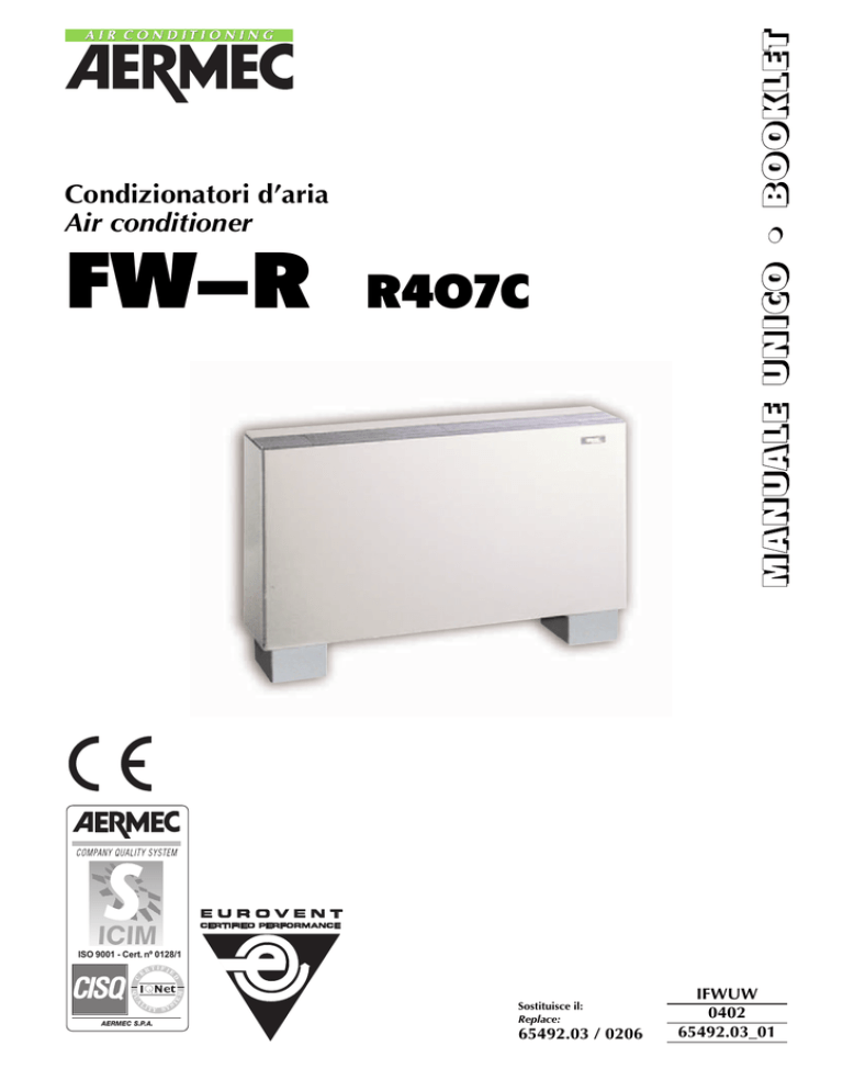
FW-R
R407C
M
MA
AN
NU
UA
ALLEE U
UN
NIIC
CO
O • B
BO
OO
OK
KLLEETT
Condizionatori d’aria
Air conditioner
ISO 9001 - Cert. nº 0128/1
C
RT
IFI
E
D
E
A
IT
T
EM
QU
L
Y SY
AERMEC S.P.A.
S
Sostituisce il:
Replace:
65492.03 / 0206
IFWUW
0402
65492.03_01
Descrizione dell’unità • Unit description
Componenti principali • Main components
Descrizione dei componenti • Component description
Organi di sicurezza e regolazione • Safety and controls
Imballo • Packing
Accessori • Accessories
Tabella di compatibilità degli accessori • Accessories compatibility table
Dati tecnici • Technical data
Criteri di scelta • Selection
Consumo acqua al condensatore • Condenser water consumption
Perdite di carico al condensatore • Pressure drop
Potenzialità termica resa con batteria ad acqua calda • Delivered heating capacity with water coil
Perdite di carico lato acqua nella batteria riscaldante • Heating coil water pressure drops
4
5
6
7
8
9
10
MISURE DI SICUREZZA • SAFETY MEASURES
Usi impropri • Improper uses
Simboli di sicurezza • Safety symbol
11
INSTALLAZIONE • INSTALLATION
Trasporto • Carriage
Installazione dell’unità • Unit installation
Norme particolari per il gas refrigerante R407C • Special attention for R407C refrigerant gas
12
13
FUNZIONAMENTO • OPERATION
Istruzioni per l’uso • Operating instructions
Manutenzione • Maintenance
Individuazione guasti • Fault-finding
16
19
20
CARATTERISTICHE • FEATURES
Dati dimensioni • Dimensions
Schemi elettrici • Wiring diagrams
21
22
3
IIN
ND
DIIC
CEE •
• C
CO
ON
NTTEEN
NTTS
S
INFORMAZIONI GENERALI • GENERAL INFORMATION
CARATTERISTICHE • FEATURES
IIN
NFFO
OR
RM
MA
AZ
ZIIO
ON
NII G
GEEN
NEER
RA
ALLII •
• G
GEEN
NEER
RA
ALL IIN
NFFO
OR
RM
MA
ATTIIO
ON
N
AERMEC S.p.A.
I-37040 Bevilacqua (VR) Italia – Via Roma, 44
Tel. (+39) 0442 633111
Telefax 0442 93730 – (+39) 0442 93566
www.aermec.com
FW-R
modello:
model:
numero di serie:
serial number:
DICHIARAZIONE DI CONFORMITÀ
DECLARATION OF CONFORMITY
Noi, firmatari della presente, dichiariamo sotto la nostra
esclusiva responsabilità, che la macchina in oggetto è
conforme a quanto prescritto dalla Direttiva 73/23/CEE,
89/336/CEE, e dalla Normativa EN 60335-2-40 .
We declare under our own responsability that the above
equipment complies with provisions of Standard 73/23/EEC,
89/336/EEC and Regulation EN 60335-2-40 .
Bevilacqua, 1/1/2004
La Direzione Commerciale – Sales and Marketing Director
Luigi Zucchi
OSSERVAZIONI
REMARKS
Conservare il manuale in luogo asciutto, per evitare il
deterioramento, per almeno 10 anni per eventuali riferimenti futuri.
Store the manual in a dry location to avoid deterioration, as
they must be kept for at least 10 years for any future reference.
Leggere attentamente e completamente tutte le informazioni contenute in questo manuale.
Prestare particolarmente attenzione alle norme d’uso
accompagnate dalle scritte “PERICOLO” o “ATTENZIONE” in quanto, se non osservate, possono causare danno
alla macchina e/o a persone e cose.
All the information in this manual must be carefully read
and understood.
Pay particular attention to the operating standards with
“DANGER” or “WARNING” signals as their disrespect can
cause damage to the machine and/or persons or objects.
Per anomalie non contemplate da questo manuale, interpellare tempestivamente il Servizio Assistenza di zona.
If any malfunctions are not included in this manual, contact
the local Aftersales Service immediately.
AERMEC S.p.A. declina ogni responsabilità per qualsiasi
danno dovuto ad un uso improprio della macchina, ad una
lettura parziale o superficiale delle informazioni contenute
in questo manuale.
AERMEC S.p.A. declines all responsibility for any damage
whatsoever caused by improper use of the machine, and a
partial or superficial acquaintance with the information contained in this manual.
Il numero di pagine di questo manuale è: 24.
This manual has 24 pages
4
DESCRIPTION OF THE UNIT
CARATTERISTICHE GENERALI
I condizionatori a sistema integrato della serie FW-R sono
apparecchi autonomi progettati e realizzati per mantenere
le migliori condizioni ambientali.
Di linea sobria ed elegante, hanno un funzionamento particolarmente silenzioso che li rende adatti ad essere installati in
ambienti abitativi o commerciali.
Sono provvisti di condensatore raffreddato ad acqua ed oltre
a svolgere le tipiche funzioni di raffreddamento, deumidificazione, ventilazione e filtraggio dell’aria, presentano notevoli
vantaggi dal punto di vista dell’applicazione e dell’installazione.
Consentono infatti il riscaldamento invernale qualora vengano equipaggiati di batteria di riscaldamento (ad acqua o elettrica); realizzano un’efficace divisione in zone degli ambienti
grazie all’indipendenza del funzionamento di ogni singolo
apparecchio; assicurano economicità di servizio dovuta alla
rapida messa a regime delle condizioni ambientali in virtù
GENERAL CHARACTERISTICS
The FW-R series of integrated system conditioners are autonomous units designed and constructed to maintain the best
possible ambient conditions.
The simple, elegant design of these units is a complement to
their silent operation performance, making them ideal for
installation in commercial or domestic ambients.
The FW-R unit is equipped with a water-cooled condenser,
it not only cools, dehumidifies, fans and filters the air, but
also has important new application and installation features.
Fitted with a water or electric heating coil, these units can in
fact be used for winter heating applications; they can efficiently serve distinct areas, thanks to the independent movement of each single unit; they ensure economical performance by means of the rapid adjustment of operation to
environmental conditions, thanks to the low thermal inertia
of the system; while their thermo-acoustic insulation ensures
silent operation at all times.
COMPONENTI PRINCIPALI • MAIN COMPONENTS
1
2
3
4
5
6
Pannello comandi • Control panel
Scheda elettronica • Electronic card
Gruppo ventilatori • Section ventilation
Filtro aria • Air filter
Batteria di scambio termico • Heat exchanger
Struttura portante • Bearing structure
7 Mobile di copertura • Cabinet
8 Compressore • Compressor
9 Valvola pressostatica • Water valve
10 Condensatore ad acqua • Water cooled condenser
11 Pressostato di alta • High pressure switch
7
5
2
1
11
8
RAL 9002
3
10
4
6
9
5
C
CA
AR
RA
ATTTTEER
RIIS
STTIIC
CH
HEE •
• FFEEA
ATTU
UR
REES
S
DESCRIZIONE DELL’UNITÀ
C
CA
AR
RA
ATTTTEER
RIIS
STTIIC
CH
HEE •
• FFEEA
ATTU
UR
REES
S
della ridotta inerzia termica del sistema; hanno inoltre un funzionamento silenzioso grazie all’accurato isolamento termoacustico del vano compressore.
Tutte le unità sono completamente assemblate in fabbrica e
singolarmente collaudate.
All units are completely factory assembled and are individually tested.
MODELLI DISPONIBILI
MODELS AVAILABLE
I condizionatori della serie FW-R sono disponibili in due
grandezze, nella versione con gas frigorifero R407C:
R 407 C:
FW 137 R
FW 167 R
FW-R series air conditioners come in two sizes, available in
the version with refrigerant gas R407C:
R 407 C:
FW 137 R
FW 167 R
DESCRIZIONE DEI COMPONENTI
DESCRIPTION OF COMPONENTS
1 PANNELLO COMANDI
Posto sotto lo sportello laterale destro della macchina permette il completo controllo dell’apparecchio. Il pannello comandi è infatti dotato di un pulsante acceso/spento, di un commutatore estate/inverno, del cursore per regolare la temperatura ambiente e del selettore delle velocità del ventilatore.
1 CONTROL PANEL
The control panel is located below the r.h. panel of the
machine, and is used to control all unit functions. The control panel features ON/OFF push-button, winter/summer
selector switch, ambient temperature adjustment slider and
fan speed selector.
2 SCHEDA ELETTRONICA DI CONTROLLO
La scheda elettronica è posizionata nella scatola elettrica
ed assolve automaticamente a tutte le funzioni di regolazione e controllo.
In particolare provvede:
– all’inserimento ritardato di tre minuti del compressore al
primo avviamento e dopo ogni fermata;
– al controllo della temperatura ambiente;
– all’inserimento automatico e al controllo della resistenza
elettrica o della batteria ad acqua calda, se installata.
2 ELECTRONIC CONTROL CARD
The electronic card is located inside the electrical enclosure,
and automatically carries out all control and adjustment
functions.
In particular:
– 3-minute delayed start-up of compressor following first
start-up and after each shutdown;
– control of ambient temperature;
– automatic start-up and control of electric heater or hot
water coil (if installed).
3 GRUPPO VENTILANTE
È costituito da ventilatori centrifughi a doppia aspirazione e
pale curve in avanti, bilanciati staticamente e dinamicamente, azionati da motore elettrico monofase accoppiato
direttamente.
3 FAN ASSEMBLY
Comprising twin-suction centrifugal fans with forward curved blades, statically and dynamically balanced, powered
by a single-phase directly coupled electric motor.
4 SEZIONE FILTRANTE
Permette la filtrazione e purificazione dell’aria immessa in
ambiente. Facilmente estraibile è costruito con materiali
rigenerabili, può essere pulito mediante lavaggio.
5 BATTERIA DI SCAMBIO TERMICO
In tubo di rame ed alettatura in alluminio bloccata mediante
espansione meccanica dei tubi.
6 STRUTTURA PORTANTE
È realizzata in lamiera zincata. Ogni apparecchio è dotato
di bacinella raccolta condensa.
7 MOBILE DI COPERTURA
Realizzato in lamiera verniciata a caldo con polveri poliuretaniche dopo trattamento di passivazione per garantire alta
resistenza alla ruggine e alla corrosione.
8 COMPRESSORE
Di tipo ermetico rotativo ad elevata efficienza, azionato da
motore elettrico a due poli con protezione termica interna.
9 VALVOLA PRESSOSTATICA
Modula la portata dell’acqua allo scambiatore in modo da
mantenere la pressione di condensazione costante.
10 CONDENSATORE AD ACQUA
Del tipo a piastre in acciaio inox AISI 316.
4 FILTER SECTION
Filters and purifies air blown into the environment. Easy to
extract, this section is made from recyclable material, and
can be easily rinsed.
5 HEAT EXCHANGE COIL
Aluminium finned copper tube core held in position by the
mechanical expansion of tubes.
6 MAIN FRAME
Made from galvanised sheet metal. Each unit if fitted with a
condensate tray.
7 CABINET
Made from stoved painted stoved polyurethane powder
painted sheet metal, pre-passivated to prevent the formation
of rust or corrosion.
8 COMPRESSOR
Rotary hermetic high-efficiency compressor powered by 2pole electric motor with incorporated overload cut-out device.
9 PRESSURE VALVE
Adjusts water flow to the heat exchanger, thereby maintaining constant condensing pressure.
10 WATER COOLED CONDENSER
Plate type exchanger in stainless steel AISI 316
11 PRESSOSTATO DI ALTA
A norme TÜV, del tipo miniguard a taratura fissa e riarmo
manuale. Blocca il funzionamento del compressore nel caso
il fluido refrigerante superi la massima pressione di utilizzo.
11 HIGH PRESSURE SWITCH
Miniguard type, made to TÜV standards. Features fixed setting and manual reset. Stops the compressor when the cooling fluid pressure exceeds maximum operating pressure
values.
ORGANI DI SICUREZZA E REGOLAZIONE
SAFETY AND ADJUSTMENT DEVICES
Le unità sono progettate per climi temperati (T1 - ISO 5151)
e sono equipaggiate dei seguenti dispositivi:
– pressostato di sicurezza: del tipo a taratura fissa, é montato sul lato di alta pressione, ed é in conformità con le
vigenti norme di sicurezza;
– protezioni elettriche: il compressore e i ventilatori sono
The units have been degnined for mild climates (T1 - ISO
5151) and are equipped with the following devices:
– fixed setting safety pressure switch installed on the high
pressure side: made to current safety standards;
– electrical cut-out devices: the compressor and fans are
protected by incorporated thermal cut-out devices; the
6
electrical card is protected by a fuse;
– electrical enclosure: incorporated in the machine, with
completely pre-assembled connections;
– no-frost control: performed by the SD probe (see wiring
diagram) on the evaporator coil circuit.
FUNZIONAMENTO E REGOLAZIONE SCHEDA ELETTRONICA
La scheda elettronica controlla la temperatura ambiente e
impedisce il funzionamento in raffreddamento con temperatura inferiore a 18°C. In caso di brinamento della batteria
interna la scheda arresta il funzionamento del compressore
fino al ripristino delle normali condizioni di funzionamento.
Il funzionamento in riscaldamento è consentito solo attraverso l’utilizzo degli accessori resistenza elettrica o batteria
di riscaldamento.
Nel caso sia montata la resistenza elettrica, sarà possibile
effettuare il riscaldamento dell’ambiente scegliendo tra
commutazione stagionale manuale o automatica.
Il trimmer ZM permette di tarare la zona morta (intervallo di
temperatura tra l’inizio delle fasi di riscaldamento e raffreddamento) nel caso di funzionamento in posizione “automatico”(fig.1). Il valore può essere regolato da 1 a 6°C (standard 3°C) e viene ignorato in funzionamento normale (non
automatico).
È possibile, solo nel funzionamento in riscaldamento, termostatare il ventilatore dell’unità interna. In tal caso il
microinterruttore ETV sulla scheda dovrà essere posizionato
su OFF: il ventilatore rimarrà acceso solo se il termostato
ambiente richiede il riscaldamento.
La batteria ad acqua calda é corredata di una sonda di
minima temperatura acqua (SW). Se non si prevede il collegamento della sonda SW il microinterruttore ESW sulla
scheda elettronica dovrà essere posizionato su ON.
ELECTRONIC CARD OPERATION AND ADJUSTMENT
The electronic card monitors ambient temperature, and inhibits cooling at temperatures below 18°C. In the event of frosting of the internal coil, the card cuts out compressor operation until normal operation conditions are restored.
Heating is possible by means of the accessory electrical heater or heating coil:
electrical heater: the ambient is heated through selection of
manual or automatic seasonal switch-over.
The ZM trimmer sets the dead band (i.e. temperature interval between the beginning of the heating and cooling stages) when the unit is operating in the automatic mode
(fig.1). The value is set between 1 and 6°C (standard 3°C),
and is ignored during normal unit operation.
During the heating function, the internal fan can be thermostatically set. In this case, the ETV microswitch must be set
to the OFF position: the fan is activated only when the
ambient thermostat requires the heating function.
The heating coil is fitted with a minimum water temperature
probe (SW). If the SW probe is not connected, the ESW
microswitch should be set to the ON position.
OFF
OFF
ON
0,5
SET POINT
0,5
0,5
ON
Raffreddamento
Cooling
Riscaldamento
Heating
°C
0,5
ZM (1÷6 °C)
Fig. 1
IMBALLO
PACKING
Le unità vengono spedite con imballo standard costituito da
un basamento in legno e da una scatola di cartone.
The units are standard conditioned for shipment in a carton
box and a wooden pallets.
ACCESSORI
ACCESSORIES
BVR 1 BATTERIA DI RISCALDAMENTO AD ACQUA
La batteria di riscaldamento funzionante ad acqua calda può
essere installata nell’unità e posizionata sopra la batteria evaporante. Nella batteria è presente una sonda di minima temperatura, tale sonda impedisce il funzionamento dei ventilatori quando la temperatura dell’acqua è inferiore a 35°C.
BVR 1 HEATING COIL
The heating coil can be installed above the evaporator coil
inside the unit. The heating coil contains a minimum temperature probe, which inhibits fan operation when water temperature is below 35°C.
BR 26 BATTERIA DI RISCALDAMENTO ELETTRICA
È costituita da una resistenza elettrica del tipo corazzato da
1200 watt. A corredo della resistenza elettrica è fornita una
lamiera a protezione dell’isolamento del mobile di copertura. La batteria è fornita completa di termostati di sicurezza a
riarmo manuale e automatico.
BR 26 ELECTRIC HEATING COIL
Comprises a 1200 W electrical heater.
The electrical heater is fitted with a sheet steel panel to insulate the unit cabinet. The coil is supplied complete with a
safety thermostat, with either manual or automatic reset
function.
7
C
CA
AR
RA
ATTTTEER
RIIS
STTIIC
CH
HEE •
• FFEEA
ATTU
UR
REES
S
protetti da dispositivi di tipo termico incorporati nel componente; la scheda elettronica è protetta da un fusibile;
– quadro elettrico: incorporato nella macchina ha i collegamenti interni completamente premontati;
– controllo antigelo: effettuato tramite la sonda SD (vedi
schema elettrico) posizionata sul circuito della batteria
evaporante.
C
CA
AR
RA
ATTTTEER
RIIS
STTIIC
CH
HEE •
• FFEEA
ATTU
UR
REES
S
TABELLA DI COMPATIBILITÀ DEGLI ACCESSORI • ACCESSORIES COMPATIBILITY TABLE
Accessori disponibili • Available accessories
Mod.
FW 137 R
FW 167 R
BVR 1
✔
✔
BR 26
✔
✔
DATI TECNICI • TECHNICAL DATA
Mod.
max.
Potenzialità frigorifera
❆
med.
Cooling capacity
min.
Tipo compressore • Compressor type
Potenzialità termica batteria ad acqua
❆❆
Water coil heating capacity
❆❆Portata acqua batteria • Water coil flow rate
Perdite di carico acqua batteria
❆❆
Water coil pressure drops
Potenzialità termica batteria elettrica
Electric heating capacity
Numero di ventilatori • Fan number
max.
Portata aria
med.
Air flow
min.
max.
Velocità ventilatori
med.
Fan speed
min.
Pressione sonora • Sound pressure
Potenza sonora • Sound power
Consumo acqua a 16°C
Water consumption at 16°C
Perdite di carico condensatore
Condenser pressure drops
Gas refrigerante • Refrigerant gas
Carica refrigerante • Refrigerant gas charge
Potenza assorbita • Input power
Corrente d’esercizio • Input current
Corrente di spunto • Peak current
Altezza • Height
Dimensioni
Larghezza • Width
Dimensions
Profondità • Depth
Peso netto • Net weight
Entrata acqua • Water in
Uscita acqua • Water out
Scarico condensa • Condensate out
FW 137 R
FW 167 R
3.000
2.640
2.120
4.500
3.750
3.010
W (E)
W
W
rotativo • rotary
W
4.350
5.200
l/h
600
600
kPa
12,6
12,6
W
1.200
1.200
m3/h
m3/h
m3/h
g/m • rpm
g/m • rpm
g/m • rpm
dB (A)
dB (A)
2
470
390
270
800
660
500
44,0
52,5
2
690
525
375
1.140
885
665
47,5
56,0
l/h
187
253
kPa
2,1
3,7
kg
W
A
A
mm
mm
mm
kg
ø
ø
ø
R407C
0,53
870
4,1
23,0
723
1.121
242
63
1/2”
1/2”
1/2”
R407C
0,55
1.250
6,0
33,5
723
1.121
242
67
1/2”
1/2”
1/2”
(E) = EUROVENT CERTIFIED PERFORMANCE
=pressione sonora misurata in ambiente con volume di
85 m3 e tempo di riverbero di 0,5 s.
Tensione di alimentazione: 230 V - 1 - 50 Hz
Le prestazioni sono riferite alle seguenti condizioni:
❆ Temperatura aria entrante 27°C b.s. / 19 °C b.u.
❆❆ Temperatura aria entrante 20 °C;
Temperatura acqua entrante 70 °C
Massima velocità del ventilatore
8
=sound pressure measured in rooms with a volume of
85 m3 and reverberation time of 0,5 s.
Power supply: 230 V - 1 - 50 Hz
Performances refer to following conditions:
❆ Entering air temperature 27°C d.b. / 19 °C w.b.;
❆❆ Entering air temperature 20 °C ;
Entering water temperature 70 °C
Maximum fan speed
SELECTION
I condizionatori, vengono completamente assemblati in fabbrica e singolarmente collaudati.
Le tavole 1 e 2 riportano il consumo di acqua e le relative
perdite di carico nel condensatore.
La tavola 3 evidenzia le rese termiche degli apparecchi corredati dell’accessorio batteria ad acqua calda, mentre nella
tavola 4 sono riportate le perdite di carico dell’acqua nelle
stesse batterie.
Air conditioners are completely assembled in the factory
and singly tested.
Tables 1 and 2 show water consumption and relative load
loss values in the condenser.
Table 3 highlights heating delivery values of units equipped
with heating coils, while table 4 shows their load loss
values.
TAV 1
CONSUMO ACQUA AL CONDENSATORE • CONDENSER WATER CONSUMPTION
Portata acqua • Water flow
[l/h] 600
500
FW1
400
67R
R
137
FW
300
200
100
0
10
12
14
16
18
20
22
24
26
28
30 [°C]
Temperatura acqua ingresso condensatore • Condenser entering water temperature
PERDITE DI CARICO AL CONDENSATORE • PRESSURE DROP
[kPa] 6
Perdite di carico • Pressure drop
TAV 2
5
4
3
2
1
0
150
200
250
300
350 [l/h]
Portata acqua • Water flow
9
C
CA
AR
RA
ATTTTEER
RIIS
STTIIC
CH
HEE •
• FFEEA
ATTU
UR
REES
S
CRITERI DI SCELTA
C
CA
AR
RA
ATTTTEER
RIIS
STTIIC
CH
HEE •
• FFEEA
ATTU
UR
REES
S
TAV 2
POTENZIALITÀ TERMICA RESA CON BATTERIA AD ACQUA CALDA
DELIVERED HEATING CAPACITY WITH WATER COIL
∆t (temperatura acqua entrante - temperatura aria entrante)
∆t (temperature entering water - temperature entering air)
30°C
FW
FW
l/h x 100 4
5
16
13
7
7
40°C
50°C
60°C
70°C
R
R
6
7
2,5
3
3,5
4
4,5
5
5,5
6
6,5
7
7,5 kW
Portata acqua
Water flow
Il grafico è riferito alla massima velocità del dei ventilatori.
Per la media e la minima moltiplicare la resa ricavata
rispettivamente per:
- velocità media FC=0,86
- velocità minima FC=0,68
TAV 4
The diagram shows maximum speed of the fans.
To calculate average and minimum speeds, multiply the
capacity achieved respectively by:
- average speed
FC=0.86
- minimum speed
FC=0.68
PERDITE DI CARICO LATO ACQUA NELLA BATTERIA RISCALDANTE
HEATING COIL WATER PRESSURE DROPS
kPa 20
18
16
14
12
10
8
6
400 420 440 460 480 500 520 540 560 580 600 620 640 660 680 700 720 740 760 780 l/h
Portata acqua • Water flow
10
DO NOT COVER THE UNIT WITH OBJECTS OR CURTAINS WHICH MAY PARTIALLY OBSTRUCT AIR FLOW.
GHE
0 LE RI
20.00 O I MA
SOTT
GUERRA E PACE
ASSASSINIO SUL
L'ORIENT EXPRESS
NON COPRIRE L’UNITÀ VENTILCONVETTORE CON
OGGETTI O TENDAGGI CHE OSTRUISCANO ANCHE
PARZIALMENTE IL FLUSSO DELL'ARIA.
NON SEDERSI SOPRA L’UNITÀ.
DO NOT SIT ON THE UNIT.
SIMBOLI DI SICUREZZA • SAFETY SYMBOL
Pericolo:
Tensione
Pericolo:
Temperatura
Pericolo:
Organi in movimento
Pericolo!!!
Danger:
Power supply
Danger:
Temperature
Danger:
Movings parts
Danger!!!
11
M
MIIS
SU
UR
REE D
DII S
SIIC
CU
UR
REEZ
ZZ
ZA
A •
• S
SA
AFFEETTY
Y M
MEEA
AS
SU
UR
REES
S
USI IMPROPRI • IMPROPER USES
IIN
NS
STTA
ALLLLA
AZ
ZIIO
ON
NEE •
• IIN
NS
STTA
ALLLLA
ATTIIO
ON
N
TRASPORTO • CARRIAGE
NON bagnare • Do NOT wet
NON calpestare • Do NOT trample
NON lasciare gli imballi sciolti durante il trasporto
Do NOT leave loose packages during transport
Sovrapponibilità: controllare sull’imballo la posizione della freccia per conoscere il numero di macchine
impilabili
Stacking: control the packing for the arrow position
to know the number of machines that can be stacked
6
5
4
3
2
1
NON trasportare la macchina da soli.
DO NOT handle the machine.
12
UNIT INSTALLATION
Il condizionatore deve essere installato perfettamente orizzontale ed in posizione tale da consentire, facilmente, la
manutenzione ordinaria (pulizia del filtro) e straordinaria.
Per installare l’unità procedere come segue:
a) Rimuovere il condizionatore dall’imballo, togliere il
mobile di copertura allentando le viti (1 fig.2), sfilando il
mobile dai ganci (2 fig.2).
b) Posizionare l’apparecchio ed effettuare i collegamenti
idraulici.
Si consiglia di isolare adeguatamente le tubazioni dell’acqua
di alimentazione per evitare gocciolamenti durante il suo
funzionamento. I collegamenti possono essere eseguiti, a
seconda dell’esigenza, sia sulla parte posteriore (fig.3) sia sul
lato destro dell’apparecchio (fig.4). Per i collegamenti posteriori il pannello posteriore (1 fig.3) è provvisto di ferritoia per
il passaggio dei tubi da collegare alla squadretta di servizio
(2 fig.3) fissandoli con i raccordi (3 fig.3).
Quando gli allacciamenti idraulici vengono realizzati attraverso la fiancata destra del mobile, si ricorda che la squadretta (1 fig.4 ) dovrà essere infilata sulle tubazioni prima di
effettuare la fase finale dei collegamenti idraulici. Realizzati
i raccordi si provvederà al fissaggio della squadretta (1) al
mobile stesso mediante le viti (2) precedentemente tolte.
Si precisa che l’attacco inferiore è relativo allo scarico della
condensa, quello centrale per l’uscita dell’acqua dal condensatore, quello superiore per l’ingresso dell’acqua di raffreddamento.
Si consiglia l’installazione di un filtro a monte del condensatore.
c) Collegamento elettrico.
Per proteggere l’unità contro i cortocircuiti, montare sulla
linea di alimentazione un interruttore magnetotermico di
opportuna taratura.
Il cavo elettrico di alimentazione deve essere del tipo
H05RN-F con isolamento in gomma sintetica e guaina in
poli-cloroprene, in accordo con le norme CEI-EN60355-240 e HD277.S1.
Il cavo elettrico dovrà passare dal passacavo alloggiato nel
pannello posteriore. Dopo aver tolto il pannello di protezione della scheda, collegare il cavo di alimentazione alla
morsettiera nella scatola elettrica (fig.5). Rimontare la protezione della scheda, precedentemente tolta.
Per tutti i collegamenti seguire gli schemi elettrici a corredo
dell’apparecchio e riportati sulla presente documentazione.
The unit should always be installed in a perfectly horizontal
position, so as to facilitate routine maintenance operations
(filter cleaning) as well as unscheduled servicing.
To install the unit, proceed as follows:
a) Remove the unit from the packing; remove the screws
(1 fig.2) then the cover, sliding it out from the clips
(2 fig.2).
b) Position the unit, then make the water connections.
Always insulate the water lines to prevent leakage during
operation.Depending on requirements, connections can
be made to the rear (fig.3) or to the right side of the unit
(fig.4). When making connections to the rear of the unit,
pass the water lines through the opening in the rear panel
(1 fig.3) to the bracket (2 fig.3); secure the lines with the
couplings (3 fig.3).
When making connections through the right side of the
unit, slide the L bracket (1 fig.4 ) onto the tubes before
making water connections. After coupling has been
made, secure the L bracket (1) to the unit cabinet by
means of the screws (2) previously removed.
Note that the lower connector is for condensate drainage,
the middle connector for the water outlet from the condenser, the upper for the cooling water inlet.
It is advisable to install the filter up-line of the condenser.
NORME PARTICOLARI PER IL GAS R407C
SPECIAL ATTENTION FOR R407C GAS
Prima di ogni reintegro o ricarica accertarsi di usare lo
stesso gas frigorifero indicato nella tabella delle caratteristiche della unità condensante.
I condizionatori funzionanti con gas frigorigeno R407C richiedono
particolari attenzioni nel montaggio e nella manutenzione, al fine di
preservarli da anomalie di funzionamento.
È necessario pertanto:
- Evitare reintegri d’olio differente da quello specificato già
precaricato nel compressore. I compressori rotativi della
serie R407C utilizzano olio DAPHNE FV68S.
- In caso vi siamo fughe di gas tali da rendere il condizionatore anche solo parzialmente scarico, evitare di reintegrare la parte di fluido frigorigeno, ma scaricare completamente la macchina e dopo avere eseguito il vuoto, ricaricarla con la quantità prevista.
- In caso di sostituzione di qualsiasi parte del circuito frigorifero, non lasciare il circuito aperto più di 15 minuti.
- In particolare, in caso di sostituzione del compressore,
completare l’installazione entro il tempo sopraindicato,
dopo averne rimosso i tappi in gomma.
- Evitare che tracce di acqua possano essere presenti
all’interno del circuito frigorifero.
- In condizioni di vuoto non dare tensione al compressore;
non comprimere aria all’interno del compressore.
- Si consiglia di utilizzare le bombole di gas R407C fino ad un
livello residuo del 30%. Solo in tal caso è garantito il corretto
rapporto dei componenti della miscela gassosa R407C.
Before recharging the unit make sure any time that you are
using the refrigerant gas indicated in the table containing
the characteristics of the condensing unit.
Conditioning units using R407C refrigerant gas require special
attention during assembly and maintenance operations. To prevent
operating malfunctions, always:
c) Wiring connection.
To protect the unit from the risk of short circuits, a magnetothrmic switch
must be installated in the power line.
The power line cable must be H05RN-F type, synthetic rubber insulation and Neoprene coating according to CEIEN60355-2-40 and HD277.S1 codes.
The power line cable must be throught the hole in the back
panel.
Remove the cover from the electric box.
Connect the power line cable to the terminals, into the electric box (fig.5). Refit the cover.
For all connections refer to the wiring diagrams supplied
with the appliance and specified in this documentation.
- use the specified type of oil to top up the compressor.
R407C series rotary compressors use DAPHNE FV68S oil
only.
- In the event of significant gas charge leaks, do not replenish the refrigerant fluid. Drain the machine completely,
apply vacuum then recharge with the specified quantity.
-- In the event of replacement of refrigerant circuit parts,
never leave the circuit open for more than 15 minutes.
- In the event of compressor replacement, complete installation within 15 minutes of removal of the rubber plugs.
- eliminate all water inside the refrigerant circuit.
- Never compress air inside the compressor;
- Never power up the compressor when empty;
- Use R407C gas bottle to a residual level of 30% (only in
this case is the correct proportioning of R407C gases
ensured).
13
C
CA
AR
RA
ATTTTEER
RIIS
STTIIC
CH
HEE •
• FFEEA
ATTU
UR
REES
S
INSTALLAZIONE DELL’UNITÀ
IIN
NS
STTA
ALLLLA
AZ
ZIIO
ON
NEE •
• IIN
NS
STTA
ALLLLA
ATTIIO
ON
N
1
1
2
14
2
Fig. 2
3
1
Fig. 3
1
2
2
Fig. 4
230V - 1 - 50Hz
Fig. 5
IIN
NS
STTA
ALLLLA
AZ
ZIIO
ON
NEE •
• IIN
NS
STTA
ALLLLA
ATTIIO
ON
N
DATI ACCESSORI • ACCESSORIES DATA
BVR1
7
6
5
4
3
2
1
Fig. 6
BR26
7
6
5
4
3
2
1
Fig. 7
15
FFU
UN
NZ
ZIIO
ON
NA
AM
MEEN
NTTO
O •
• O
OP
PEER
RA
ATTIIO
ON
N
ISTRUZIONI PER L’USO • OPERATING INSTRUCTIONS
Il pannello di comando si trova sotto lo sportello laterale
destro della macchina.
Control panel is located under the right side plastic cover of
the unit.
b) Per accendere l’unità:
To turn on the unit :
O
b) Scegliere il funzionamento:
Select operating mode:
Estate • Summer
16
É un’operazione eseguibile solamente se presente
l’accessorio batteria ad acqua calda o resistenza
elettrica.
This operation is only possible when the heating coil
or electrical heater are installed.
O
Posizione intermedia • Intermediate position
E un’operazione eseguibile solamente se presente
l’accessorio resistenza elettrica.
This operation is only possible when the electrical
heater are installed.
La posizione intermedia (A) indica il funzionamento
con commutazione automatica caldo-freddo
The intermediate position (A) indicates operation
with automatic heating-cooling switch-over.
17
FFU
UN
NZ
ZIIO
ON
NA
AM
MEEN
NTTO
O •
• O
OP
PEER
RA
ATTIIO
ON
N
Inverno • Winter
FFU
UN
NZ
ZIIO
ON
NA
AM
MEEN
NTTO
O •
• O
OP
PEER
RA
ATTIIO
ON
N
c) Scegliere la velocità del ventilatore:
Select fan coil speed:
I = Minima II = Media
III = Massima.
Per una rapida messa a regime degli ambienti, si consiglia di impostare la massima velocità. Si usufruisce così
dell’intera potenzialità dell’unità.
I = Minimum II = Medium
III = Maximum.
For a rapid stabilisation of room conditions, set the maximum speed. This will exploit the whole capacity of the
unit.
d) IMPOSTARE LA TEMPERATURA:
1 = massimo RAFFREDDAMENTO;
7 = massimo RISCALDAMENTO.
Se l'impostazione del termostato è tale da richiedere il funzionamento, si accenderà la luce gialla e si avvierà il ventilatore.
Per ottenere il massimo comfort all'avvio, posizionare il
cursore nella posizione 1 per il funzionamento in raffreddamento, e 7 per il funzionamento in riscaldamento. Quando
l'ambiente avrà raggiunto una temperatura gradevole, muovere il cursore in senso contrario fino allo spegnimento
della luce gialla.
SET THE TEMPERATURE:
1 = maximum COOLING;
7 = maximum HEATING.
If the thermostat is pre-set to select temperatures, a yellow
pilot light glows and the fan starts.
To obtain maximum comfort at start, put the cursor on position 1 to activate cooling and 7 to activate heating.
When room has reached a satisfactory temperature, move
the cursor clockwise till the yellow warning light turns off.
e) Per spegnere l’unità:
To turn off the unit:
18
O
L’unità AERMEC è costruita con tecnologie moderne che ne
assicurano l’efficenza ed il funzionamento nel tempo.
Pertanto l’unica manutenzione che necessita è la pulizia del
filtro dell’aria per avere un funzionamento ottimale
dell’unità e, soprattutto, per
ottenere una corretta filtrazione dell’aria.
È sufficiente pulire periodicamente il filtro, estraendolo dalla sua sede.
Il lavaggio può essere effettuato con acqua corrente e
normali detergenti, occorre
asciugare bene il filtro
prima di riposizionarlo
nella sua sede. Una pulizia
quindicinale può essere
sufficiente per ambienti
non eccessivamente polverosi.
The AERMEC unit is constructed with state of the art technology that ensures long-term efficiency and operation.
The only maintenance required is to clean the air filters,
which optimises the unit operation and, above all, achieves
an effective filtration of
the air.
It is quite sufficient to
periodically wash the
filter, by simply sliding
it out of its housing.
The filter can be
washed with tap water
and usual detergents.
Make sure it is dry
before replacing in its
housing.
Cleaning every fifteen
days is enough for
rooms which are not
excessively dusty.
PULIRE IL FILTRO !
CLEAN THE FILTER !
PERICOLO
DANGER
– PER PULIRE L’UNITÀ:
Non indirizzare getti d’acqua sull’unità.
Può causare scosse elettriche o danneggiare l’unità.
Non usare acqua calda, sostanze abrasive
o solventi; per pulire l’unità usare un
panno soffice.
– TO CLEAN THE UNIT:
Do not splash water on the unit. It could
result in electrical shock or damage to the
product.
Do not use hot water, abrasive powders or
strong solvents; to clean the unit use a soft
cloth.
19
FFU
UN
NZ
ZIIO
ON
NA
AM
MEEN
NTTO
O •
• O
OP
PEER
RA
ATTIIO
ON
N
MANUTENZIONE • MAINTENANCE
FFU
UN
NZ
ZIIO
ON
NA
AM
MEEN
NTTO
O •
• O
OP
PEER
RA
ATTIIO
ON
N
INDIVIDUAZIONE GUASTI • FAULT-FINDING
PROBLEMA
PROBABILE CAUSA
SOLUZIONE
POCA ARIA IN USCITA
ERRATA IMPOSTAZIONE DELLA
VELOCITÀ SUL PANNELLO COMANDI
FILTRO INTASATO
OSTRUZIONE DEL FLUSSO D’ARIA
(ENTRATA E/O USCITA)
SCEGLIERE LA VELOCITÀ SUL
PANNELLO COMANDI (Pag. 18)
PULIRE IL FILTRO (Pag. 19)
RIMUOVERE L’OSTRUZIONE
NON FA CALDO
IMPOSTAZIONE ERRATA PANNELLO
COMANDI
IMPOSTARE PANNELLO COMANDI
(Pag. 16)
RESISTENZA ELETTRICA NON FUNZIONA
MANCANZA DI CORRENTE
CONTROLLARE LA PRESENZA
DI TENSIONE ELETTRICA
INTERVENUTO TERMOSTATO DI
SICUREZZA A RIARMO MANUALE
INTERPELLARE IL SERVIZIO
ASSISTENZA
POSIZIONAMENTO ERRATO
TERMOSTATI
VERIFICARE LA GIUSTA POSIZIONE
FILTRO INTASATO
OSTRUZIONE DEL FLUSSO D’ARIA
PULIRE IL FILTRO (Pag. 19)
RIMUOVERE L’OSTRUZIONE
(ENTRATA E/O USCITA)
INTERVENUTO TERMOSTATO DI
SICUREZZA A RIARMO AUTOMATICO
SE IL PROBLEMA È PERSISTENTE
INTERPELLARE IL SERVIZIO ASSISTENZA
FUNZIONAMENTO INTERMITTENTE
RESISTENZA ELETTRICA
NON FA FREDDO
IL VENTILATORE NON GIRA
IMPOSTAZIONE ERRATA PANNELLO
COMANDI
MANCANZA DI CORRENTE
IMPOSTARE PANNELLO COMANDI
(Pag. 17)
CONTROLLARE LA PRESENZA
DI TENSIONE ELETTRICA
Per anomalie non contemplate, interpellare tempestivamente il Servizio Assistenza.
PROBLEM
PROBABLE CAUSE
REMEDY
FEEBLE AIR DISCHARGE
WRONG SPEED SETTING ON
THE CONTROL PANEL
BLOCKED FILTER
OBSTRUCTION OF THE AIR FLOW
(INLET AND/OR OUTLET)
SELECT THE SPEED ON
THE CONTROL PANEL (Pag. 18)
CLEAN THE FILTER (Pag. 19)
REMOVE THE OBSTRUCTION
IT DOES NOT HEAT
WRONG SETTING ON
CONTROL PANEL
SEE CONTROL PANEL SETTINGS
(Pag. 16)
ELECTRICAL HEATER FAULT
NO CURRENT
CONTROL THE POWER SUPPLY
MANUAL RESET SAFETY
THERMOSTAT TRIPPED
CONTACT THE CUSTOMER
ASSISTANCE TECHNICAL OFFICE
THERMOSTATS INCORRECTLY
POSITIONED
CHECK POSITION OF
THERMOSTATS
BLOCKED FILTER
CLEAN THE FILTER (Pag. 19)
OBSTRUCTION OF THE AIR FLOW
(INLET AND/OR OUTLET)
REMOVE THE OBSTRUCTION
AUTOMATIC RESET SAFETY
THERMOSTAT TRIPPED
IF THE PROBLEM PERSISTS,CONTACT
THE ASSISTANCE TECHNICAL OFFICE
WRONG SETTING ON
CONTROL PANEL
NO CURRENT
SEE CONTROL PANEL SETTINGS
(Pag. 17)
CONTROL THE POWER SUPPLY
INTERMITTENT ELECTRICAL
HEATER OPERATION
IT DOES NOT COOL
THE FAN DOES NOT TURN
For anomalies don’t hesitate, contact the aftersales service immediately!
20
C
CA
AR
RA
ATTTTEER
RIIS
STTIIC
CH
HEE •
• FFEEA
ATTU
UR
REES
S
DATI DIMENSIONALI • DIMENSIONS
(mm)
B
A
C
Mod.
A
B
C
FW 137 R
723
1121
242
FW 167 R
723
1121
242
192
237
282
55
22,5
21
C
CA
AR
RA
ATTTTEER
RIIS
STTIIC
CH
HEE •
• FFEEA
ATTU
UR
REES
S
SCHEMI ELETTRICI • WIRING DIAGRAMS
LEGENDA - READING KEY
AP
= Pressostato di alta pressione
High pressure switch
SCD = Pannello comandi
Control panel
CCP = Contattore compressore
Compressor contactor
SD
= Sonda antigelo
Antifreeze sensor
CM
= Condensatore di marcia
Running capacitor
TR
= Trasformatore
Transformer
CP
= Compressore
Compressor
TSRE = Termostato a riarmo automatico
Automatic resetting thermostat
CRE
= Contattore resistenza elettrica
Electric heater contactor
TSRM = Termostato a riarmo manuale
Manual resetting thermostat
ESW = Microinterruttore gestione sonda acqua (SW)
Water probe control by microswitch (SW)
ZM
= Trimmer regolazione zona morta da 1 a 6°C
Dead band trimmer 1 - 6°C
ETV
= Microinterruttore termostatazione ventilatore
Fan thermostat control microswitch
Collegamenti da eseguire in loco
Field wiring
IG
= Interruttore generale
Main switch
Componenti non forniti
Components not supplied
MV
= Motore ventilatore
Fan motor
Accessori
Accessories
PT
= Protezione compressore
Compressor protection
RE
= Resistenza elettrica
Electric heater
SA
= Sonda ambiente
Room sensor
SC
= Scheda di controllo
Electronic control board
1,5 mm
BL
= Blu - Blue
MA
= Marrone - Brown
NE
= Nero - Black
RO
= Rosso - Red
GI
= Giallo - Yellow
2
Gli schemi elettrici sono soggetti ad aggiornamento; è opportuno fare riferimento allo schema elettrico allegato all' apparecchio.
Wiring diagrams may change for updating. It is therefore necessary to refer always to the wiring diagram inside the units.
22
Aermec partecipa al Programma di
Certificazione EUROVENT.
I prodotti interessati figurano nella Guida
EUROVENT dei Prodotti Certificati.
I dati tecnici riportati nella presente documentazione non sono impegnativi.
L’Aermec S.p.A. si riserva la facoltà di apportare in qualsiasi momento
tutte le modifiche ritenute necessarie per il miglioramento del prodotto.
AERMEC S.p.A.
I-37040 Bevilacqua (VR) - Italia
Via Roma, 44 - Tel. (+39) 0442 633111
Telefax 0442 93730 - (+39) 0442 93566
www.aermec.com
Aermec is partecipating in the EUROVENT
Certification Programme.
Products are as listed in the EUROVENT
Directory of Certified Products.
Technical data shown in this booklet are not binding.
Aermec S.p.A. shall have the right to introduce at any time whatever
modifications deemed necessary to the improvement of the product.
carta riciclata
recycled paper
papier recyclé
recycled Papier

