REGOLATORE DI
LIVELLO A 3 SONDE
E 097
LEVEL REGULATOR
WITH 3 PROBES
Undecal
Undecal
DEFINIZIONE E UTILIZZO
Il regolatore di livello funziona sul
principio della conducibilità, quindi è
adatto per controllare il livello di
massima e di minima dei liquidi
conduttori (in particolare acqua). Non é
adatto per nafta,benzina e derivati.
FUNCTION AND USE
The level regulator works on the
principle of the conductivity and it is
suitable for the control of the maximum
and minimum levels of conductor
liquids (especially water). It is not
suitable for diesel oil, petrol and its byproducts.
CARATTERISTICHE E
REGOLAZIONI
TECHNICAL
FEATURES
REGULATIONS
SENS
Regolazione
a
cacciavite
della
sensibilità di scatto da 4kΩ a 33kΩ
circa.
Per liquidi poco conduttivi ruotare tutto
a destra.
VISUALIZZAZIONI
ON LED VERDE alimentazione
presente
LED ROSSO è acceso quando
il relè è ON
FUNZIONAMENTO
Il dispositivo utilizza 3 sonde, delle
quali una è:
AND
SENS
Regulation by screw driver of the
sensitivity from 4kΩ to 33kΩ approx.
For low conductive liquids, turn to
clock-wise.
VISUALIZATIONS
ON GREEN LED
RED LED
supply on
it lights on when
the relay is ON
MODE OF OPERATION
The device works with three probes
which are:
Sonda di “MASSA” (M)
deve rimanere sempre in immersione
(può essere utilizzato il contenitore
stesso se conduttore).
GROUND PROBE (M)
It must be always submerged in the
liquid (the reservoir can be used as
ground probe when it is made of
conductive material).
Sonda “LUNGA” (L)
per il controllo del livello minimo.
LONG PROBE (L)
It controls the minimum level.
Sonda “CORTA” (C)
per il controllo del livello massimo.
Le sonde sono alimentate in corrente
alternata e quindi non si presentano i
ben noti fenomeni dell’elettrolisi.
SHORT PROBE (C)
It controls the maximum level
The probes are supplied with
alternated current, so that the
electrolysis does not take place.
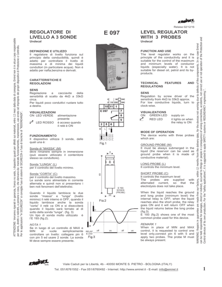
Quando il liquido lambisce le due
sonde “massa” e “lunga” (livello
minimo) il relè interno è OFF, quando il
liquido lambisce anche la sonda
“corta” il relè va ON e si disecciterà
quando il liquido sarà tornato al di
sotto della sonda “lunga”. (fig. 3)
Un tipo di sonda molto utilizzato è
l’E 193 (fig.2).
When the liquid reaches the ground
and long probe (minimum level) the
internal relay is OFF; when the liquid
reaches also the short probe, the relay
goes ON and it will return OFF when
the liquid returns below the long probe
(fig.3).
E 193 (fig.2) shows one of the most
common probe used for this device.
NOTA 1
Se in luogo di un controllo di MAX e
MIN
si
vuole
semplicemente
controllare un livello: collegare pin 6
con pin 5 ed usare 2 sonde. La sonda
M deve sempre essere presente.
REMARK 1
When in place of MIN and MAX
control, it is requested to control one
level only,connect pin 6 with 5 and
apply two probes. The probe M must
be always present.
WARNING: Repairs in guarantee are made free our factory, within 12 months from the delivery date, for the devices not working due to defects of the components. In no case Emirel
can be held responsible for damages, direct or indirect, occurred to things or people in consequence of wrong connections, accidents, not correct use or not operation of the Protection and
Control devices of its own production. For the "safety applications", it is suggested to apply SAFETY systems or REDUNDANCY engineering.".
ATTENZIONE: Verranno riparati in garanzia, franco ns sede, i dispositivi guasti per difetti sui materiali, entro 12 mesi dalla data di consegna. Emirel non è in alcun caso responsabile
per danni, diretti o indiretti, a persone o cose, che derivano da: mancato funzionamento, manomissioni, uso errato od improprio dei propri dispositivi di Protezione e Controllo.
Per le applicazioni "in SICUREZZA" si consiglia l'uso di sistemi di SICUREZZA o l'uso di tecniche di "RIDONDANZA".
Relaise 02/12/16
Viale Caduti per la Libertà, 4b - 40050 MONTE S. PIETRO - BOLOGNA (ITALY)
Tel. 051/6761552 - Fax 051/6760492 - Internet: http://www.emirel.it - E-mail: [email protected]
1
TARATURA
Regolare la SENS a seconda della
conducibilità
del
liquido.
Con
sensibilità BASSA il dispositivo non
riconosce la presenza di un liquido
poco conduttivo.
SETTING
Fix SENS according to the liquid
conductivity. When SENS is turned to
a low sensitivity, the device does not
see the presence of a liquid with low
conductivity.
INSTALLAZIONE
Eseguire i collegamenti di fig.1.
(Collegamento a un quadro elettrico
con differenziale e sezionatore).
La lunghezza di ogni collegamento
deve essere < 30m.
INSTALLATION
Electric wiring to be made as per fig.1.
(Wiring to an electrical board with a
differential relay and a sectionalizing
switch). The lenght of every wiring
must be less than 30m.
INGRESSI
(SONDE) tensione massima 11Vac
pin 2 : SONDA “MASSA”
pin 5 : SONDA “LUNGA” (livello min.)
pin 6 : SONDA “CORTA” (livello max).
Il filo di collegamento delle sonde
aggiunge una resistenza in serie al
liquido (ad esempio 1 mm2 presenta
15Ω/km. E’ bene tenere questa
resistenza aggiuntiva < di 30 ohm, per
ogni sonda. Si consiglia l’uso di filo
con 600 Vac di isolamento per lunghi
tratti.
NOTA 2
La differenza fra il livello MAX e min,
dipende dalla collocazione
delle
sonde C ed L.
USCITA: 5A - 230 Vac - carico
resistivo
8-9 NC
8-7 NA
ALIMENTAZIONE: 2VA - 50÷60 Hz
Tolleranza: -10%÷+6%
10-11 : 115 Vac
10-1 : 230 Vac (24 Vac a richiesta)
DIMENSIONI: 48x96x90 mm con
innesto per zoccolo undecal.
Accessori disponibili a richiesta:
E 171 : ganci per montaggio da
incasso.
E 172 : zoccolo femmina undecal per
DIN.
M 13A: protezione plexiglas piombabile IP54.
E 346 : molle di sostegno antisfilamento.
Dima di Foratura: 45x92 mm
TEMP. DI FUNZIONAMENTO: 0÷70°C
PESO: 0,300 kg
COLORE: nero
Per la pulizia usare un panno imbevuto
con detergenti privi di: Alcool denaturato, Benzene, Alcool isopropilico.
COMPATIBILITA' ELETTRO
MAGNETICA
Electromagnetic compatibility
CEI-EN 61326-1
“BASSA TENSIONE” - LVD
LVD – “LOW VOLTAGE”
CEI-EN 61010-1
Nota generale: Negli schemi di
collegamento non sono riportati i
fusibili sulle alimentazioni e sugli
ingressi voltmetrici.
I collegamenti elettrici devono essere
eseguiti a dispositivo e quadro
elettrico spenti.
General remark: The wiring
diagrammes do not show the fuses
installed on the supply and on the
voltmetric inputs.
The electric wirings must be realized
with device and electrical panel in off
condition.
INPUT
PROBES: max voltage 11Vac
pin 2 : GROUND PROBE
pin 5 : LONG PROBE - minimum level
pin 6 : SHORT PROBE – max. level
The wire connecting the probes adds a
“series” resistance to the liquid (ex.: 1
mm2 wire has 15Ω/km resistance).
This added resistance should be less
than 30 ohm for each probe.
It is suggested to apply a 600 Vac
insulated wire for long distance.
REMARK 2
The difference between MAX and min
level depends on the location of C and
L probes.
OUTPUT: 5A-230 Vac - resistive load
8-9 NC
8-7 NO
SUPPLY: 2VA - 50÷60 Hz
Tolerance: -10%÷+6%
10-11 : 115 Vac
10-1 : 230 Vac (24 Vac on request)
SIZE: 48x96x90 mm
undecal male base.
Accessories available on request:
E 171 : hooks for flush mounting.
E 172 : undecal female base for DIN.
M 13A: plexiglas protection IP 54tight
closure.
E 346 : hold spring protecting from
vibrations.
Template: 45x92 mm
WORKING TEMPERATURE: 0÷70°C
WEIGHT: 0,300 kg
COLOUR: black
For cleaning use a cloth soaked with
detergents without: Denatured alcohol,
Benzene, Isopropyl Alcohol.
Viale Caduti per la Libertà, 4b - 40050 MONTE S. PIETRO - BOLOGNA (ITALY)
2
Tel. 051/6761552 - Fax 051/6760492 - Internet: http://www.emirel.it - E-mail: [email protected]

