JOLLY MINI 1-10V
LED Driver, DC1-10V, 150W
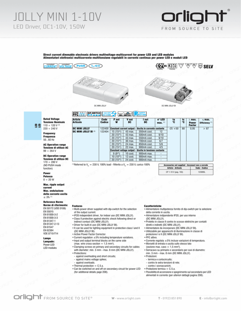
Direct current dimmable electronic drivers multivoltage-multicurrent for power LED and LED modules
Alimentatori elettronici multicorrente-multitensione regolabili in corrente continua per power LED e moduli LED
SELV
05
PENDING
LED
LED
DC MINI JOLLY
Rated Voltage
Tensione Nominale
110 ÷ 120 V (2)
220 ÷ 240 V
Frequency
Frequenza
50...60 Hz
DC MINI JOLLY BI
Article
Articolo
Code
Codice
DC MINI JOLLY
DC MINI JOLLY BI (2)
122400 Constant current output - Uscita in corrente costante
122404 15 (15(2)) 43 max.
350mA cost.
12
20 (15(2)) 43 max.
500mA cost.
9/10
20 (15(2)) 43 max.
550mA cost.
9/10
20 (15(2)) 36 max.
700mA cost.
6/7
20 (15(2)) 24 max.
850mA cost.
5/6
(2)
20 (15 ) 22 max.
900mA cost.
4/5
AC Operation range
Tensione di utilizzo AC
99 ÷ 264 V
DC Operation range
Tensione di utilizzo DC
170 ÷ 280 V
(NO PUSH mode
function)
PENDING
P out
W
V out
DC
I out
DC
n° LED
max. (1)
ta
°C
tc
°C
-25 +50
80
l max.
Power
Factor
0,95
h max.
Efficiency (1)
> 87
Constant voltage output - Uscita in tensione costante
9 (9(2))
10 (10(2))
20 (15(2))
(1)
10 cost.
12 cost.
24 cost.
900mA max.
900mA max.
900mA max.
Referred to Vin = 230 V, 100% load - Riferito a Vin = 230 V, carico 100%
Accessories not supplied - Accessori non a corredo
Article - Articolo
Code - Codice
CP 1-10 V (pag. 193)
Power
Potenza
0 ÷ 20 W
123999L
Max. ripple output
current
Max. ondulazione
della corrente uscita
≤ 3% (1)
Reference Norms
Norme di riferimento:
EN 50172 (VDE 0108)
EN 55015
EN 61000-3-2
EN 61000-3-3
EN 61347-1
EN 61347-2-13
EN 61547
EN 62384
VDE 0710-T14
Lamps
Lampade:
Power LED
LED modules
44
Features
• Multi-power driver supplied with dip-switch for the selection
of the output current.
• IP20 independent driver, for indoor use (DC MINI JOLLY).
• Class II protection against electric shock following direct or
indirect contact (DC MINI JOLLY).
• Driver for built-in use (DC MINI JOLLY BI).
• It can be used for lighting equipment in protection class I and II
(DC MINI JOLLY BI).
• Active Power Factor Corrector.
• Current regulation ±5% including temperature variations.
• Input and output terminal blocks on the same side
(max. wire cross-section = 1,5 mm2).
• Clamping screws on primary and secondary circuits for cables
with diameter: min. 3 mm - max. 8 mm (DC MINI JOLLY).
• Protections:
- against overheating and short circuits;
- against mains voltage spikes;
- against overloads.
• Thermal protection = C.5.a.
• Can be switched on and off on secondary circuit for power LED
(for additional details page 208).
TCI professional light applications
www.tci.it
FROM SOURCE TO SITE ®
Caratteristiche
• Alimentatore multipotenza fornito di dip-switch per la selezione
della corrente in uscita.
• Alimentatore indipendente IP20, per uso interno
(DC MINI JOLLY).
• Protetto in classe II contro le scosse elettriche per contatti
diretti e indiretti (DC MINI JOLLY).
• Alimentatore da incorporare (DC MINI JOLLY BI).
• Utilizzabile per apparecchi di illuminazione in classe di
protezione I e II (DC MINI JOLLY BI).
• PFC attivo.
• Corrente regolata ±5% incluse variazioni di temperatura.
• Morsetti di entrata e uscita sullo stesso lato
(sezione max. cavo = 1,5 mm2).
• Serracavo su primario e secondario per cavi di diametro:
min. 3 mm - max. 8 mm (DC MINI JOLLY).
• Protezioni:
- termica e cortocircuito;
- contro le extra-tensioni di rete;
- contro i sovraccarichi.
• Protezione termica = C.5.a.
• Possibilità di accensione e spegnimento sul secondario per LED
alimentati in corrente (per ulteriori dettagli pagina 208).
W - www.orlight.com T - 01923 851 890 E - [email protected]
JOLLY MINI 1-10V
LED Driver, DC1-10V, 150W
Direct current dimmable electronic drivers multivoltage-multicurrent for power LED and LED modules
Alimentatori elettronici multicorrente-multitensione regolabili in corrente continua per power LED e moduli LED
Weight - Peso gr. 108
Pcs - Pezzi 50
Ø55
Weight - Peso gr. Pcs - Pezzi -
108
108
52
27,5 52
100
22
22
92
110,4
Wiring diagram - Schema di collegamento (Max. LED distance at page 201 - Massima distanza LED a pagina 201)
SEC
6 5 4 32 1
+
_
+
1...10 V _
LED
PRI
SEC
+
_
LED
1...10 V
+
_
1...10 V
PUSH
PUSH
N
L
PUSH diagram - Collegamento PUSH
LED
LED
6 5 4 32 1
PUSH
N
L
PRI
N
L
N
L
1...10 V diagram - Collegamento 1...10 V
Operation Mode
• Light regulation 0-100% by means of PUSH function, 1...10 V interface
(I=0,35 mA) or 100 Kohm potentiometer.
• Light regulation 0-100% by mains of PUSH function
(L mains voltage: 170 Kohm):
- a short push to turn on and off;
- a longer push to increase or decrease light intensity;
- regulation automatically stops at minimum and maximum values;
- for another on, regulation or off command, release the push button and give
the desired command again.
• Maximum length of the cable, from push button to last driver, must be
max. 15 m. In case of applications where the cable is longer than 15 m,
keep this separate from the 110-240 Volt mains cable.
• ATTENTION: only use normally open push buttons with no incorporated
warning light.
• Specific dimming terminal connection with a 1...10 Vdc electronic
potentiometer (1…10 V local dimming, double insulation required for external
connection).
For additional details for regulations see pages 206-207.
Modalità di funzionamento
• Regolazione della luminosità 0-100% mediante funzione PUSH, Interfaccia
1...10 V (I=0,35 mA) o potenziometro da 100 Kohm.
• Regolazione della luminosità 0-100% mediante la funzione PUSH (tensione
di rete L; 170 Kohm):
- una pressione breve per accendere e spegnere;
- una pressione prolungata per aumentare o diminuire l’intensità luminosa;
- la regolazione si ferma automaticamente ai valori minimi e massimi;
- per un nuovo comando accensione, regolazione o spegnimento, rilasciare il
pulsante e dare nuovamente il comando desiderato.
• La lunghezza massima del cavo, dal pulsante all’ultimo trasformatore,
deve essere max. 15 m. In caso di applicazioni dove il cavo superi i 15 m,
tenere lo stesso separato dal cavo di rete 110-240 Volt.
• ATTENZIONE: usare solo pulsanti di tipo normalmente aperto privi di spia
luminosa incorporata.
• Provvisto di morsetto specifico per la regolazione collegando un
potenziometro elettronico 1...10 Vdc (dimmerazione locale 1…10 V, per
connessioni esterne all’apparecchio garantire il doppio isolamento).
Per ulteriori dettagli sulle regolazioni vedi pagine 206-207.
TCI professional light applications
FROM SOURCE TO SITE ®
www.tci.it
W - www.orlight.com 45
T - 01923 851 890 E - [email protected]

