TERMOSTATO AMBIENTE TERMO14
Istruzioni per l‘installazione
IMPIEGHI
Questo termostato è particolarmente indicato per la regolazione automatica del riscaldamento e del
condizionamento dei più svariati ambienti (abitazioni, alberghi, scuole, uffici, officine ecc.). Esso è adatto anche a
molteplici altre applicazioni concernenti riscaldamento e condizionamento sia civile che industriale.
DATI TECNICI TERMO 14
Termostato unipolare a montaggio indipendente non elettronico
- Campo di regolazione: +5 / +30°C
- Portata dei contatti:
- Differenziale: ∆t ≤ 1K
TERMO 14.1 16(2,5)A 250V ~ (*) ; TERMO 14.2 e
- Gradiente termico: 1K /15 min.
TERMO 14.3 10(1,5)A 250V ~ ; TERMO 14.4 10(1,5)A 250V ~
- Elemento sensibile: polmone ad
- Dispositivo di classe I
espansione di vapore
- Grado di protezione: IP 20
- Contatti in argento 1000/1000
- Azioni di tipo 1B
- Contatti di interruzione o commutazione - Situazione di inquinamento del dispositivo:
- Tensione impulsiva nominale: 4kV
grado di polluzione 2
(*) La portata di 16(2,5)A 250V è condizionata all’impiego per il collegamento di conduttori flessibili.
In caso di impiego di conduttori rigidi la portata si intende ridotta a 10(2,5)A 250V.
COLLOCAZIONE
E’ consigliabile scegliere per il termostato una collocazione in una zona che rispecchi il più possibile le condizioni di
temperatura media di tutto l’ambiente. Va evitata l’immediata vicinanza di porte, finestre, fonti di calore, posizioni
con eccesso o totale mancanza di aerazione.
Si consiglia inoltre di montare il termostato ambiente a circa 1,5 m dal pavimento.
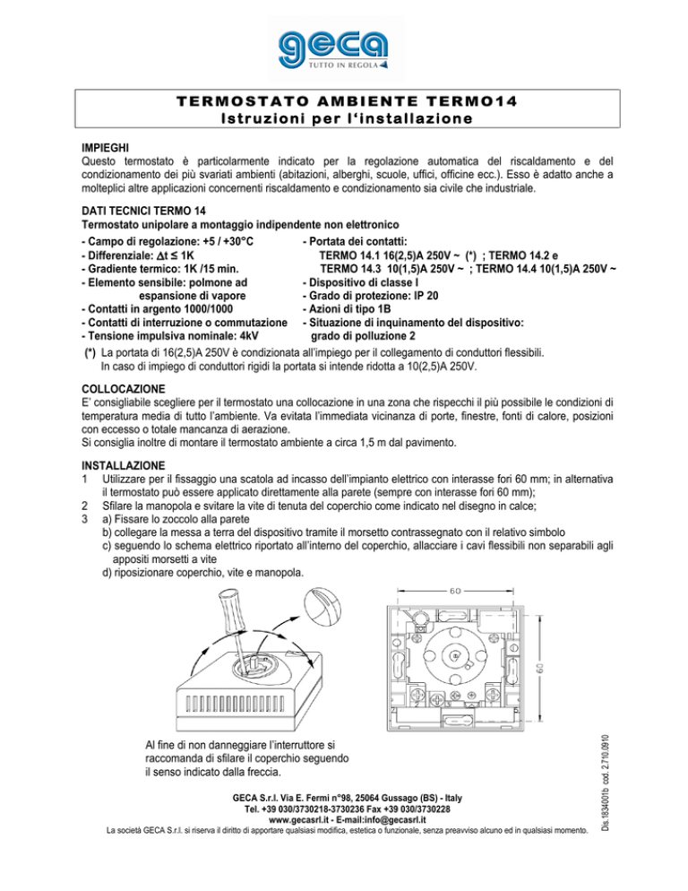
Al fine di non danneggiare l’interruttore si
raccomanda di sfilare il coperchio seguendo
il senso indicato dalla freccia.
GECA S.r.l. Via E. Fermi n°98, 25064 Gussago (BS) - Italy
Tel. +39 030/3730218-3730236 Fax +39 030/3730228
www.gecasrl.it - E-mail:[email protected]
La società GECA S.r.l. si riserva il diritto di apportare qualsiasi modifica, estetica o funzionale, senza preavviso alcuno ed in qualsiasi momento.
Dis.1834001b cod. 2.710.0910
INSTALLAZIONE
1 Utilizzare per il fissaggio una scatola ad incasso dell’impianto elettrico con interasse fori 60 mm; in alternativa
il termostato può essere applicato direttamente alla parete (sempre con interasse fori 60 mm);
2 Sfilare la manopola e svitare la vite di tenuta del coperchio come indicato nel disegno in calce;
3 a) Fissare lo zoccolo alla parete
b) collegare la messa a terra del dispositivo tramite il morsetto contrassegnato con il relativo simbolo
c) seguendo lo schema elettrico riportato all’interno del coperchio, allacciare i cavi flessibili non separabili agli
appositi morsetti a vite
d) riposizionare coperchio, vite e manopola.
AMBIENT THERMOSTAT TERMO14
Installation instructions
USES
This thermostat is designed for automatic regulation of heating and conditioning systems in houses, Hotels,
schools, offices, workshops and many other environments, both domestic and industrial. It is also ideal for heating
and air conditioning numerous industrial and civil applications.
TECHNICAL SPECIFICATIONS TERMO 14
Free mounted non-electric single-pole thermostat
- Setting range: +5 / +30°C
- Capacity of the contacts:
- Differential: ∆t ≤ 1K
TERMO 14.1 16(2,5)A 250V ~ (*) ; TERMO 14.2 and
- Thermal gradient: 1K / 15 min.
TERMO 14.3 10(1,5)A 250V ~ ; TERMO 14.4 10(1,5)A 250V ~
- Sensitive element: vapour expansion lung
- Protection against shock: I
- Silver contacts 1000/1000
- Degree of protection: IP20
- Break or switching contacts
- Type of action: 1B
- Rated pulsating voltage: 4kV
- Pollution level of the device: degree of pollution 2
(*) The current carrying capacity of 16(2.5)A 250V depends on the use of flexible leads for the connections.
If rigid leads are used, the capacity is reduced to 10(2.5)A 250V.
POSITIONING
You are advised to position the thermostat as far as possible in a place that reflects the average temperature of the
whole area. Avoid positioning it near doors, windows, sources of heat and in places where there is too much or too
little ventilation.
The thermostat should be fitted at approximately 1.5 m from the ground.
INSTALLATION
1 The thermostat can be fitted to the flush-mounting box of the electric system (centre distance 60 mm) or
directly to the wall (centre distance 60 mm);
2 Remove the knob and unscrew the screw of the cover as shown in the drawing;
3 a) Fix the base to the wall
b) connect the thermostat earth by using the terminal marked with the earth symbol
c) follow the wiring diagram inside the cover; fix the flexible inseparable wires to the relative screw terminals
d) replace the cover, screws and knob.
To avoid any damage to the switch
we recommend to remove the cover
according to the direction of the arrow.
GECA S.r.l. Via E. Fermi n°98, 25064 Gussago (BS) - Italy
Tel. +39 030/3730218-3730236 Fax +39 030/3730228
www.gecasrl.it - E-mail:[email protected]
GECA S.r.l. reserves the right to make any aesthetic or functional modification without prior notice at any time.

