BIG1F-SLY
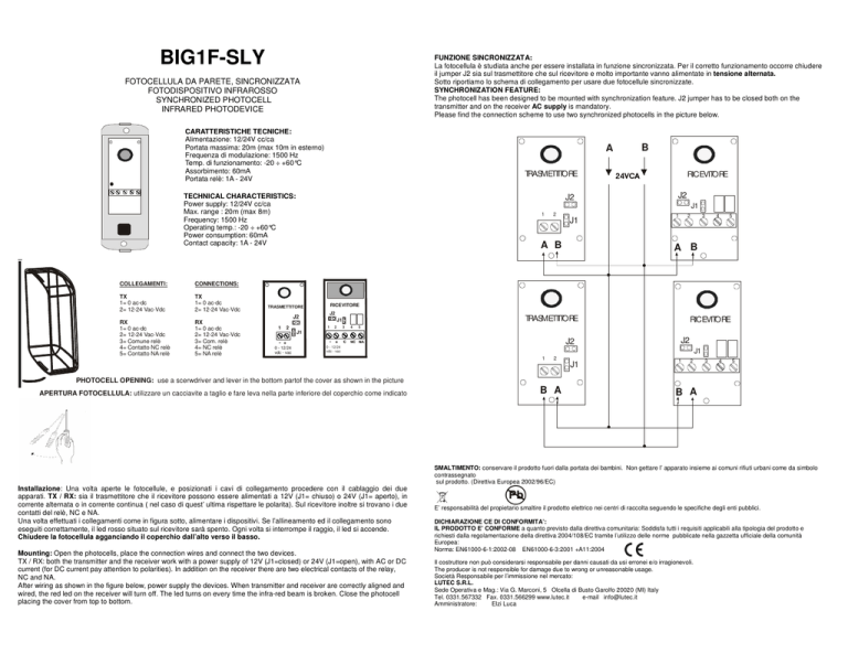
FUNZIONE SINCRONIZZATA:
La fotocellula è studiata anche per essere installata in funzione sincronizzata. Per il corretto funzionamento occorre chiudere
il jumper J2 sia sul trasmettitore che sul ricevitore e molto importante vanno alimentate in tensione alternata.
Sotto riportiamo lo schema di collegamento per usare due fotocellule sincronizzate.
SYNCHRONIZATION FEATURE:
The photocell has been designed to be mounted with synchronization feature. J2 jumper has to be closed both on the
transmitter and on the receiver AC supply is mandatory.
Please find the connection scheme to use two synchronized photocells in the picture below.
FOTOCELLULA DA PARETE, SINCRONIZZATA
FOTODISPOSITIVO INFRAROSSO
SYNCHRONIZED PHOTOCELL
INFRARED PHOTODEVICE
CARATTERISTICHE TECNICHE:
Alimentazione: 12/24V cc/ca
Portata massima: 20m (max 10m in esterno)
Frequenza di modulazione: 1500 Hz
Temp. di funzionamento: -20 ÷ +60°C
Assorbimento: 60mA
Portata relè: 1A - 24V
A
TRASMETTITORE
TECHNICAL CHARACTERISTICS:
Power supply: 12/24V cc/ca
Max. range : 20m (max 8m)
Frequency: 1500 Hz
Operating temp.: -20 ÷ +60°C
Power consumption: 60mA
Contact capacity: 1A - 24V
COLLEGAMENTI:
CONNECTIONS:
TX
1= 0 ac-dc
2= 12-24 Vac-Vdc
TX
1= 0 ac-dc
2= 12-24 Vac-Vdc
RX
1= 0 ac-dc
2= 12-24 Vac-Vdc
3= Comune relè
4= Contatto NC relè
5= Contatto NA relè
RX
1= 0 ac-dc
2= 12-24 Vac-Vdc
3= Com. relè
4= NC relè
5= NA relè
J2
RICEVITORE
J2
J1
1
2
J1
A B
J2
J2
2
1
2
3
4
5
A B
RICEVITORE
TRASMETTITORE
1
B
TRASMETTITORE
J1
1
2
3
4
RICEVITORE
5
J1
- +
- +
0 - 12/24
vdc - vac
0 - 12/24
vdc - vac
J2
J2
J1
1
2
J1
1
2
3
4
5
PHOTOCELL OPENING: use a scerwdriver and lever in the bottom partof the cover as shown in the picture
APERTURA FOTOCELLULA: utilizzare un cacciavite a taglio e fare leva nella parte inferiore del coperchio come indicato
B A
B A
SMALTIMENTO: conservare il prodotto fuori dalla portata dei bambini. Non gettare l’ apparato insieme ai comuni rifiuti urbani come da simbolo
contrassegnato
sul prodotto. (Direttiva Europea 2002/96/EC)
Installazione: Una volta aperte le fotocellule, e posizionati i cavi di collegamento procedere con il cablaggio dei due
apparati. TX / RX: sia il trasmettitore che il ricevitore possono essere alimentati a 12V (J1= chiuso) o 24V (J1= aperto), in
corrente alternata o in corrente continua ( nel caso di quest’ ultima rispettare le polarita). Sul ricevitore inoltre si trovano i due
contatti del relè, NC e NA.
Una volta effettuati i collegamenti come in figura sotto, alimentare i dispositivi. Se l’allineamento ed il collegamento sono
eseguiti correttamente, il led rosso situato sul ricevitore sarà spento. Ogni volta si interrompe il raggio, il led si accende.
Chiudere la fotocellula agganciando il coperchio dall’alto verso il basso.
Mounting: Open the photocells, place the connection wires and connect the two devices.
TX / RX: both the transmitter and the receiver work with a power supply of 12V (J1=closed) or 24V (J1=open), with AC or DC
current (for DC current pay attention to polarities). In addition on the receiver there are two electrical contacts of the relay,
NC and NA.
After wiring as shown in the figure below, power supply the devices. When transmitter and receiver are correctly aligned and
wired, the red led on the receiver will turn off. The led turns on every time the infra-red beam is broken. Close the photocell
placing the cover from top to bottom.
E’ responsabilità del propietario smaltire il prodotto elettrico nei centri di raccolta seguendo le specifiche degli enti pubblici.
DICHIARAZIONE CE DI CONFORMITA’:
IL PRODOTTO E’ CONFORME a quanto previsto dalla direttiva comunitaria: Soddisfa tutti i requisiti applicabili alla tipologia del prodotto e
richiesti dalla regolamentazione della direttiva 2004/108/EC tramite l’utilizzo delle norme pubblicate nella gazzetta ufficiale della comunità
Europea:
Norma: EN61000-6-1:2002-08 EN61000-6-3:2001 +A11:2004
Il costruttore non può considerarsi responsabile per danni causati da usi erronei e/o irragionevoli.
The producer is not responsible for damage due to wrong or unreasonable usage.
Società Responsabile per l’immissione nel mercato:
LUTEC S.R.L.
Sede Operativa e Mag.: Via G. Marconi, 5 Olcella di Busto Garolfo 20020 (MI) Italy
Tel. 0331.567332 Fax. 0331.566299 www.lutec.it
e-mail [email protected]
Amministratore:
Elzi Luca

