Helios Italquartz srl
Via Delle Industrie 103/a
20040 CAMBIAGO –MI
Tel. ++39.02.95.34.93.18 r.a.
Fax ++39.02.95.34.50.85
[email protected]
www.heliositalquartz.com
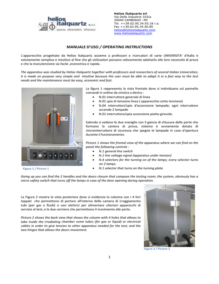
MANUALE D'USO / OPERATING INSTRUCTIONS L'apparecchio progettato da Helios Italquartz assieme a professori e ricercatori di varie UNIVERSITA' d'Italia è volutamente semplice e intuitivo al fine che gli utilizzatori possano velocemente adattarlo alle loro necessità di prova e che la manutenzione sia facile ,economica e rapida. The apparatus was studied by Helios Italquartz together with professors and researchers of several Italian Universities; it is made on purpose very simple and intuitive because the user must be able to adapt it in a fast way to the test needs and the maintenance must be easy, economic and fast. La figura 1 rappresenta la vista frontale dove si individuano sul pannello comandi in ordine da sinistra a destra : N.01 interruttore generale di linea N.01 spia di tensione linea ( apparecchio sotto tensione) N.04 interruttori/spia d'accensione lampade; ogni interruttore accende 2 lampade N.01 interruttore/spia accensione piatto girevole. Salendo si vedono le due maniglie con il gancio di chiusura delle porte che formano la camera di prova; sistema è ovviamente dotato di microinterruttore di sicurezza che spegne le lampade in caso d'apertura durante il funzionamento. Picture 1 shows the frontal view of the apparatus where we can find on the panel the following controls : N.1 general line switch N.1 line voltage signal (apparatus under tension) N.4 selectors for the turning on of the lamps; every selector turns on 2 lamps. N.1 selector that turns on the turning plate. Figura 1 / Picture 1 Going up you can find the 2 handles and the doors closure that compose the testing room; the system, obviously has a micro safety switch that turns off the lamps in case of the door opening during operation. La Figura 2 mostra la vista posteriore dove si evidenzia la colonna con i 4 fori tappati che permettono di portare all'interno della camera di irraggiamento tubi (per gas o fluidi) o cavi elettrici per alimentare ulteriori apparecchi di servizio al test; e le due cerniere che permettono il movimento alle porte. Picture 2 shows the back view that shows the column with 4 holes that allows to take inside the irradiating chamber some tubes (for gas or liquid) or electrical cables in order to give tension to other apparatus needed for the test; and the two hinges that allows the doors movement. Figura 2 / Picture 2 1 Helios Italquartz srl
Via Delle Industrie 103/a
20040 CAMBIAGO –MI
Tel. ++39.02.95.34.93.18 r.a.
Fax ++39.02.95.34.50.85
[email protected]
www.heliositalquartz.com
Figura 4 Fusibile di linea
Sul basamento posteriore troviamo la connessione femmina per il cavo d'alimentazione e i due fusibili di linea facilmente sostituibili. On the back of the base you can find the female connection for the tension cable and the two line fusible of easy substitution . La figura 5 mostra la vista frontale con le porte aperte dove si evidenzia il ventilatore di raffreddamento della camera, le lampade UV (n.5 per ogni porta), il doppio ‐ piatto girevole, la colonna di sostegno delle porte con i 4 fori d'accesso dall'esterno e i due supporti per il fissaggio delle pinze di supporto per reattori fissi che non necessitano dei piatti girevoli. Picture 5 shows the frontal view with the open doors and we can see the fan for the chamber cooling, the UV lamps (n.5 for every door), the double turning plate, the column with the 4 holes for the external access to the chamber and the two supports for the tongs for the fixing of the static reactors that do not need the turning plates. Figura 5 Vista frontale con porte aperte
Figura 3 Vista Basamento Posteriore In queste foto viene mostrato l'accesso al cablaggio elettrico e dove sono posizionati i fusibili del trasformatore a 24V e del motore dei piatti girevoli. In these pictures it is shown the way to access to the electrical box where are positioned the fusible of the transformer at 24V and the engine of the turning plate. 2 Helios Italquartz srl
Via Delle Industrie 103/a
20040 CAMBIAGO –MI
Tel. ++39.02.95.34.93.18 r.a.
Fax ++39.02.95.34.50.85
[email protected]
www.heliositalquartz.com
In queste immagini indichiamo come poter variare l'altezza del disco superiore porta provette secondo necessità e come togliere la struttura dei piatti rotanti per fare esposizioni statiche. In these pictures it s shown how it is possible to change the height of the upper plate according to the test needs and how to take out the structure of the turning plates for the static expositions. Mostriamo ora come cambiare le lampade; svitando le ghiere di protezione alla polvere e all'umidità del portalampade e facendo fare alla lampada un piccola rotazione abbiamo la possibilità di sfilarla facilmente (esattamente come un normale neon). We show now how to change the lamps; you must twist off the ring that protects the lamp holder from dust and humidity and making the lamp do a little turn, in this way you will be able to take out the lamp easily just like you do for a normal neon tube. 3

