1
2
DE
L
ÜSM-LED 230-65
ÜSM-LED 230-65 (Art.-Nr. 5092 478)
L
Produktbeschreibung
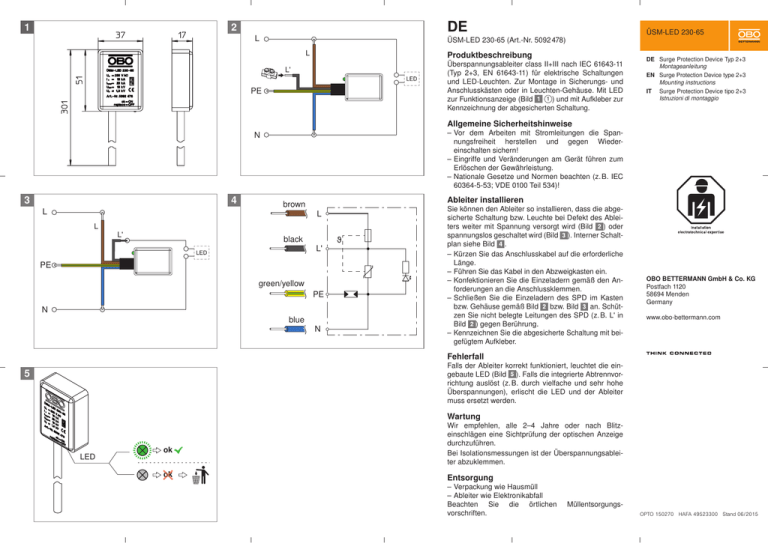
Überspannungsableiter class II+III nach IEC 61643-11
(Typ 2+3, EN 61643-11) für elektrische Schaltungen
und LED-Leuchten. Zur Montage in Sicherungs- und
Anschlusskästen oder in Leuchten-Gehäuse. Mit LED
1 ) und mit Aufkleber zur
zur Funktionsanzeige (Bild
Kennzeichnung der abgesicherten Schaltung.
L'
PE
DE Surge Protection Device Typ 2+3
Montageanleitung
EN Surge Protection Device type 2+3
Mounting instructions
IT
Surge Protection Device tipo 2+3
Istruzioni di montaggio
Allgemeine Sicherheitshinweise
–– Vor dem Arbeiten mit Stromleitungen die Spannungsfreiheit herstellen und gegen Wieder­
einschalten sichern!
–– Eingriffe und Veränderungen am Gerät führen zum
Erlöschen der Gewährleistung.
–– Nationale Gesetze und Normen beachten (z. B. IEC
60364-5-53; VDE 0100 Teil 534)!
N
3
4
L
L
L'
brown
black
Ableiter installieren
L
L'
PE
green/yellow
PE
N
blue
N
Sie können den Ableiter so installieren, dass die abgesicherte Schaltung bzw. Leuchte bei Defekt des Ableiters weiter mit Spannung versorgt wird (Bild ) oder
spannungslos geschaltet wird (Bild ). Interner Schaltplan siehe Bild .
–– Kürzen Sie das Anschlusskabel auf die erforderliche
Länge.
–– Führen Sie das Kabel in den Abzweigkasten ein.
–– Konfektionieren Sie die Einzeladern gemäß den Anforderungen an die Anschlussklemmen.
–– Schließen Sie die Einzeladern des SPD im Kasten
bzw. Gehäuse gemäß Bild
bzw. Bild
an. Schützen Sie nicht belegte Leitungen des SPD (z. B. L' in
Bild ) gegen Berührung.
–– Kennzeichnen Sie die abgesicherte Schaltung mit beigefügtem Aufkleber.
OBO BETTERMANN GmbH & Co. KG
Postfach 1120
58694 Menden
Germany
www.obo-bettermann.com
Fehlerfall
Falls der Ableiter korrekt funktioniert, leuchtet die eingebaute LED (Bild ). Falls die integrierte Abtrennvorrichtung auslöst (z. B. durch vielfache und sehr hohe
Überspannungen), erlischt die LED und der Ableiter
muss ersetzt werden.
5
Wartung
LED
ok
ok
Wir empfehlen, alle 2–4 Jahre oder nach Blitz­
einschlägen eine Sichtprüfung der optischen ­Anzeige
durchzuführen.
Bei Isolationsmessungen ist der Überspannungsableiter abzuklemmen.
Entsorgung
–– Verpackung wie Hausmüll
–– Ableiter wie Elektronikabfall
Beachten Sie die örtlichen
vorschriften.
Müllentsorgungs­
OPTO 150270 HAFA 49523300 Stand 06/2015
Installing arresters
Technische Daten
ÜSM-LED 230-65
Art. Nr.:
Abmessungen
5092478
siehe Bild
Gewicht
ca. 75 g
UN
230 V ~ (50 Hz)
UCS
255 V ~ (50 Hz)
In (8/20)
10 kA
Imax (8/20)
20 kA
Itotal (8/20)
20 kA
UOC
10 kV
max. Vorsicherung
16 A gL/Gg
Up
< 1,3 kV
Schutzart
Gehäusewerkstoff
IP 65
Thermoplast, UL 94
Einbauort
Einsatztemperaturbereich
Innenraum
-15 °C – +60 °C
IEC 61643-11
class II+III
EN 61643-11
Typ 2+3
Schutzpfad
L–N und N–PE
IPE
Topologie
Ports
< 0,5 mA
kombiniertes SPD
One-port SPD
You can install the arrester in such a way that, if the
arrester is defective, the protected circuit or luminaire
continues to be supplied with voltage (Figure ) or is
de-energised (Figure ). Internal circuit diagram, see
Figure .
–– Shorten the connection cable to the required length.
–– Run the cable into the junction box.
–– Terminate the individual wires according to the requirements for the connection terminals.
–– Connect the individual wires of the SPD in the box or
housing according to Fig.
or Fig. . Protect unassigned cables of the SPD (e.g. L‘ in Figure )
against contact.
–– Label the protected circuit with the enclosed sticker.
Faults
If the arrester functions correctly, the integrated LED
lights up (Figure ). If the integrated cut-off unit trips
(e.g. due to age on account of multiple very high overvoltages), the LED will go out. In this case, arrester
must be replaced.
Maintenance
We recommend carrying out a visual check of the visual display every 2-4 years or after lightning strikes.
During insulation measurements, disconnect the surge arrester.
Disposal
–– Packaging as household waste
–– Arrester as electronic waste
Comply with the local waste disposal regulations.
Technical data
ÜSM-LED 230-65
Item no.:
EN
ÜSM-LED 230-65 (Item no. 5092 478)
Product description
Class II+III surge arrester in accordance with IEC
61643-11 (Type 2+3, EN 61643-11) for electrical circuits and LED luminaires. For installation in fuse and
connection boxes or luminaire housings. With LED for
1 ) and with a sticker to lafunction display (Figure
bel the protected circuit.
General safety information
–– Before working on power cables, ensure that they
are de-energised and secure them against unintentional switch-on!
–– Intervention in and changes to the device will render
the warranty null and void.
–– Comply with national laws and standards (e.g. IEC
60364-5-53; VDE 0100 Part 534)!
Dimensions
Weight
5092478
See Figure
Approx. 75 g
UN
230 V ~ (50 Hz)
UCS
255 V ~ (50 Hz)
In (8/20)
Imax (8/20)
10 kA
20 kA
Itotal (8/20)
20 kA
UOC
10 kV
Max. back-up fuse
Up
16 A gL/Gg
< 1.3 kV
Protection rating
IP 65
Housing material
Thermoplast, UL 94
Installation
location
Use temperature
range
Interior
-15 °C – +60 °C
IEC 61643-11
Class II+III
EN 61643-11
Protection path
Type 2+3
L–N and N–PE
IPE
< 0.5 mA
Topology
Combined SPD
Ports
One-port SPD
IT
ÜSM-LED 230-65 (Art.-Nr. 5092 478)
Descrizione del prodotto
Limitatore di sovratensione classe II+III secondo IEC
61643-11 (tipo 2+3, EN 61643-11) per circuiti elettrici e
luci a LED. Per il montaggio nei quadri dei fusibili e di
collegamento o nell‘alloggiamento della lampada. Con
1 )
LED per la visualizzazione delle funzioni (figura
e con adesivi per la marcatura del circuito di sicurezza.
Indicazioni generali di sicurezza
–– Prima di iniziare a lavorare con i cavi della corrente,
accertare che la tensione sia assente e non possa
essere ripristinata!
–– Interventi e modifiche all‘apparecchio invalidano la
garanzia.
–– Osservare le leggi e le norme nazionali (ad es. IEC
60364-5-53; VDE 0100 parte 534)!
Installazione del deviatore
È possibile installare il deviatore in modo tale che, in
caso di difetto del deviatore, il circuito o la lampada
continui ad essere in tensione (figura ) o venga disattivato (figura ). Schema elettrico interno vedere
figura .
–– Accorciare il cavo di connessione per ottenere la
lunghezza necessaria.
–– Inserire il cavo nelle scatole di derivazione.
–– Confezionare i cavi singoli secondo i requisiti dei
morsetti di collegamento.
–– Collegare i cavi singoli del SPD nel quadro o
nell‘alloggiamento in base alla figura
o alla figura
. Proteggere i cavi non utilizzati del SPD (ad es. L‘
in figura ) dal contatto.
–– Marcare il circuito di sicurezza con l‘adesivo fornito.
Caso di guasto
Se il deviatore funziona correttamente, il LED installato è acceso (figura ). Se l‘unità di separazione integrata scatta (ad es. a causa di molteplici ed elevate
sovratensioni), il LED si spegne e il deviatore deve
essere sostituito.
Manutenzione
Si consiglia di eseguire un controllo visivo o una visualizzazione ottica ogni 2-4 anni o dopo un fulmine.
La misurazione dell‘isolamento richiede il serraggio
del limitatore di sovratensione.
Smaltimento
–– La confezione come i rifiuti domestici
–– Il deviatore come i rifiuti elettronici
Osservare le direttive locali per lo smaltimento dei rifiuti.
Dati tecnici
ÜSM-LED 230-65
Art. Nr.:
Misure
Peso
5092478
vedere figura
ca. 75 g
UN
230 V ~ (50 Hz)
UCS
255 V ~ (50 Hz)
In (8/20)
10 kA
Imax (8/20)
20 kA
Itotale (8/20)
20 kA
UOC
10 kV
Fusibile a monte
max.
Up
Grado di
protezione
Materiale cassetta
Luogo di
montaggio
Range di
temperatura di
lavoro
16 A gL/Gg
< 1,3 kV
IP 65
Thermoplast, UL 94
All'interno
-15 °C – +60 °C
IEC 61643-11
classe II+III
EN 61643-11
Tipo 2+3
Percorso di
protezione
IPE
L–N e N–PE
< 0,5 mA
Tipologia
SPD combinato
Porte
One-Port-SPD

