cod. +050000156 - rel. 1.3 - 09.11.2007
HYFC****** Dispositivo elettronico di controllo per unità fan coil / Electronic control device for fan coil units
Thank you for having chosen this product. We trust
you will be satisfied with your purchase.
Vi ringraziamo per la scelta fatta, sicuri che sarete
soddisfatti del vostro acquisto.
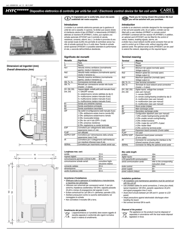
Dimensioni ed ingombri (mm)
Overall dimensions (mm)
Introduzione
Introduction
L'e-drofan è un controllo elettronico pensato per la gestione di
unità fan coil e cassette. In opzione, l'e-drofan può essere dotato
di interfaccia utente di tipo (HYPA00*) o telecomando (HYHS00*)
abbinato al ricevitore IR (HYIR00*), inoltre, può ospitare una
scheda opzionale (HYVC00*) per il controllo di valvole,
resistenze, consensi, allarmi, ecc.). L'e-drofan è provvisto di una
rete seriale locale (tLAN) che permette di controllare senza l'ausilio di schede opzionali fino a 5 unità slave. Tramite le schede
seriali opzionali (HYSC00*) è possibile estendere le performance
di rete, a seconda dell'architettura desiderata.
e-drofan is an electronic controller designed for the management
of fan coil and cassette units. As an option, e-drofan can be
fitted with a user interface (HYPA00*) or remote control
(HYHS00*) combined with the receiver IR (HYIR00*); in addition,
an optional card (HYVC00*) can be fitted for the control of
valves, heaters, enabling signals, alarms, etc.
e-drofan has a local network (tLAN) serial connector that can be
used to control up to 5 Slave units, without requiring other
optional cards. The optional serial cards (HYSC00*) can be used
to extend the network, depending on the required layout.
Significato dei morsetti
Terminal meaning
Morsetto
L
N
No1
Terminal
L
N
No1
37
No2
20
No3
GN, Tx, V+
GN, Tx
DI1, DI2, DI3,
DI4, DI5
B1
B2
B3
DIP
EXP
FLAP
SUPPLY EXP
65
IR
SERIAL
95
5
Lunghezza max. cavi:
sonde:
ingressi digitali:
comunicazione pannello LCD/reti tLAN:
comunicazione schede seriali:
5
85
5
Significato
Fase
Neutro
Velocità minima ventilatore (normalmente
aperto). Uscita in tensione (L)
Velocità media ventilatore (normalmente aperto).
Uscita in tensione (L)
Velocità massima ventilatore (normalmente
aperto). Uscita in tensione (L)
Connessione terminale utente
Morsetti per connessione seriale rete locale
(master + 5 slave).
Ingressi digitali, contatti puliti (vedi manuale d’uso):
1= ON/OFF remoto
2= estate/inverno remoto (abilitata da dip 2)
3= multifunzione (vedere manuale d’uso)
4= multifunzione (vedere manuale d’uso)
5= multifunzione (vedere manuale d’uso)
Sonda aria ambiente (ripresa)
Sonda scambiatore principale
Sonda scambiatore secondario
Dip switch di configurazione (vedi manuale d’uso):
1 ON= abilitazione estate inverno (sonda B2)
2 ON= abilitazione estate/inverno remoto
3 ON= funzionalità limitata
4 ON= fan coil 4 tubi (OFF= 2 tubi)
5 ON= presenza resistenza
6 ON= regolazione su sonda terminale
Connettore per collegamento della scheda
espansione (cavo a 5 vie)
non utilizzato
Connettore per l’alimentazione della scheda
espansione (cavo 2 vie)
Connettore per il collegamento dell’interfaccia
con ricevitore infrarossi (cavo 8 vie)
Connettore per inserimento schede seriali opz.
ingombro scheda HYVC0*
HYFC0*
150
5
160
comando caldaia:
alimentazione:
uscite di potenza (relè)
10 m
30 m
30 m
consultare foglio
istruzione relativo
30 m
5m
30 m
No2
No3
GN, Tx, V+
GN, Tx
DI1, DI2, DI3,
DI4, DI5
B1
B2
B3
DIP
EXP
FLAP
SUPPLY EXP
IR
SERIAL
Meaning
Phase
Neutral
Minimum fan speed (normally open).
Voltage output (L)
Medium speed fan (normally open).
Voltage output (L)
Maximum speed fan (normally open).
Voltage output (L)
User terminal connection
Terminals for local network serial connection
(master + 5 slave).
Digital inputs, voltage-free contacts
(see user manual):
1= remote ON/OFF
2= remote cooling/heating (enabled by dip 2)
3= multifunction (see user manual)
4= multifunction (see user manual)
5= multifunction (see user manual)
Room probe (intake)
Main exchanger probe
Secondary exchanger probe
Configuration dipswitch (see user manual):
1 ON= enable heating/cooling (probe B2)
2 ON= enable remote cooling/heating
3 ON= limited functions
4 ON= 4-pipe fan coil (OFF= 2-pipe)
5 ON= heater fitted
6 ON= control by terminal probe
Expansion board connector (5-wire cable)
not used
Expansion board power connector
(2-wire cable)
Connector for connecting the interface to the
infrared receiver (8-wire cable)
Connector for fitting the optional serial cards
Max cable length:
probes:
digital inputs:
LCD panel/tLAN communication:
serial communication cards:
boiler control:
power supply:
power outputs (relays)
10m
30m
30m
refer to the corresponding
instruction sheet
30m
5m
30m
Avvertenze d’installazione
• Effettuare tutte le operazioni di installazione e manutenzione
a macchina non alimentata.
• Utilizzare cavi schermati per connessioni seriali, 2 cavi più
schermo, impedenza caratteristica 120 Ohm, capacità parassita
40 pf/m e tempo di propagazione del segnale 5 ns/m;
• Evitare cortocircuiti tra i pin GN e V+ (alimentaz. pannello LCD).
• Adottare precauzioni contro le scariche elettrostatiche nel
maneggiare la scheda.
• Non connettere il morsetto GN a terra.
Installation guidelines
• All installation and maintenance operations must be carried out
with the unit off.
• Use shielded cables for serial connections, 2 wires plus shield,
typical impedance 120 Ohm, parasitic capacitance 40 pf/m
and signal propagation time 5 ns/m;
• Avoid short-circuits between pin GN and V+ (power to LCD
panel).
• Adopt precautions against electrostatic discharges when
handling the board.
• Not connect terminal GN to earth.
Smaltimento del prodotto
L'apparecchiatura (o il prodotto) deve essere oggetto di
raccolta separata in conformità alle vigenti normative
locali in materia di smaltimento.
Disposal of the product
The appliance (or the product) must be disposed of
separately in accordance with the local waste disposal
legislation in force.
GN Tx V+ GN Tx
Protezione contro le scosse elettriche
Protection against electric shock
Il sistema composto dalla scheda controllo (HYFC000***) e dalle
altre schede opzionali (HYVC00****, HYPA00****, HYIR00****,
HYSC00**C*, schede seriali pCO, ecc.) costituisce un dispositivo
di comando da incorporare in apparecchiature di tipo classe I o II.
La classe relativa alla protezione contro le scosse elettriche
dipende dalla modalità con cui viene eseguita l'integrazione del
dispositivo di comando nella macchina realizzata dal costruttore.
La protezione contro i cortocircuiti deve essere garantita dal
costruttore dell'apparecchiatura in cui il dispositivo di comando
viene integrato o dall’installatore finale.
The system made up of the control board (HYFC000***) and the
other optional cards (HYVC00****, HYPA00****, HYIR00****,
HYSC00**C*, pCO serial cards etc..) constitutes a control
device to be incorporated into class I or II units. The class of
protection against electric shock depends on how the control
device is integrated into the unit built by the manufacturer.
Protection against short-circuits must be guaranteed by the
manufacturer of the unit that the control device is integrated into
or by the installer.
Modifica parametri
Parameter settings
Per l’impostazione dei parametri è richiesto l’utilizzo di uno dei
seguenti dispositivi: terminale remoto, scheda seriale o chiave di
programmazione.
To set the parameters, one of the following devices must be
used: remote terminal, serial card or programming key.
Caratteristiche tecniche
Technical specifications
Alimentazione
Power supply
Exemple of Broadcast network
GN Tx V+ GN Tx
.....
GN Tx V+ GN Tx DI1 DI1 DI2 DI2 DI3 DI3 DI4 DI4
user interface
N
L
HYPA0010*
No3 No2 No1
N
N
N
L
L
HYFC00000* hydrofan controller
GN Tx V+ GN Tx
HYFC00000*
HYFC00000*
fan coil
slave2
comunicazione seriale
serial communication
fan coil
slave1
infrared receiver (optional)
IR
SERIAL
EXP
230 Vac, -15/10%; 50/60 Hz
Massima potenza assorbita (escluso
carichi dei relè): 4VA
Morsetti a vite
tensione max: 230 V;
(alimentaz. unità
sezione cavi: 14…22 AWG
esterna)
La corrente in ingresso assorbita dalla
rete (somma delle correnti assorbite dai
carichi più quella del modulo esterno) non
deve superare i 6 A.
Uscite relè No1,
corrente max.:
No2, No3
• VDE0631: 6 (2) A, 250 Vac
Tipo di azione micro-interruzione dei relè:
1C
Isolamento tra Bassa (uscite relè) e
bassissima tensione: Rinforzato
Ingressi digitali
Standard elettrico: contatto pulito
Corrente di chiusura riferita a massa: 5 mA
Massima resistenza per chiusura: 50 Ω
Ingressi analogici
Sonde di temperatura NTC CAREL
(10 kΩ a 25 °C)
B1= sonda ambiente
B2= sonda scambiatore principale
B3= sonda scambiatore secondario
Grado di protezione
IP00
Condizioni di stoccaggio
-20T80 °C, umidità 80%
U.R. non condensante
Condizioni di funzionamento
0T60 °C, umidità <90%
U.R. non condensante
Grado di inquinamento
Normale
Categoria di resistenza al
calore e al fuoco
D
PTI dei materiali di
isolamento
tutti i materiali hanno PTI≥250
Classe e struttura del software A
Periodo delle sollecitazioni
elettriche delle parti isolanti
lungo
230 Vac, -15/10 %; 50/60 Hz
Maximum power input (excluding relay
loads): 4 VA
Screw terminals
max voltage: 230 V;
(external unit PS) cable cross-section: 14 to 22 AWG
The total current input (sum of the current
inputs of the loads plus the external
module) must not exceed 6 A.
Relay outputs
max current.:
No1, No2, No3
• VDE0631: 6 (2) A, 250 Vac
Type of relay disconnection or
microswitching: 1C
Insulation between low (relay outputs) and
very low voltage parts: Reinforced
Digital inputs
Electrical standard: voltage-free contact
Closing current referred to earth: 5 mA
Maximum closing resistance: 50 Ω
Analogue inputs
CAREL NTC temperature probes (10 kΩ
at 25 °C)
B1= room probe
B2= main exchanger probe
B3= secondary exchanger probe
Index of protection
IP00
Storage conditions
-20T80°C, 80%
rH non-condensing
Operating conditions
0T60°C, <90%
rH non-condensing
Degree of pollution
Normal
Category of resistance
to heat and fire
D
PTI of insulating materials
all the materials have PTI≥250
Software class and structure A
Period of electrical stress
across the insulating parts
long
Functional characteristics
contatto
acqua
fredda
cold
water
contact
contatto
acqua
calda
hot
water
contact
Risoluzione ingressi analogici:
sonde di temp.: intervallo -25T90 °C, 0.1 °C
Errore di misura in temperatura:
• Intervallo -20T25 °C, ±0.5 °C (escluso errore sonda)
• Intervallo 25T30 °C, ±1 °C (escluso errore sonda)
• Intervallo 30T90 °C, ±1.5 °C (escluso errore sonda)
Resolution of the analogue inputs:
temp. probes: range -25T90 °C, 0.1 °C
Temperature measurement error:
• Range -20T25 °C, ±0.5 °C (excluding probe error)
• Range 25T30 °C, ±1 °C (excluding probe error)
• Range 30T90 °C, ±1.5 °C (excluding probe error)
valvola
acqua
calda
hot
water
valve
valvola
acqua
fredda
cold
water
valve
No6 No6 No7 No7
N No4 N No5
valve board (optional)
Caratteristiche funzionali
HYVC0*
DIP
B3
remote ON/OFF
B2
SUMMER/WINTER
B1
ECO
DI5
SAFETY
HYIR0002*
.....
fan coil
slave5
HYFC00000*
Schema di collegamento
Connection diagram
AVVERTENZE IMPORTANTI
Il prodotto CAREL è un prodotto avanzato, il cui funzionamento è
specificato nella documentazione tecnica fornita col prodotto o
scaricabile, anche anteriormente all’acquisto, dal sito internet
www.carel.com.
Il cliente (costruttore, progettista o installatore dell’equipaggiamento finale) si assume ogni responsabilità e rischio in relazione
alla fase di configurazione del prodotto per il raggiungimento dei
risultati previsti in relazione all’installazione e/o equipaggiamento
finale specifico.
La mancanza di tale fase di studio, la quale è richiesta/indicata
nel manuale d’uso, può generare malfunzionamenti nei prodotti
finali di cui CAREL non potrà essere ritenuta responsabile.
Il cliente finale deve usare il prodotto solo nelle modalità descritte
nella documentazione relativa al prodotto stesso.
La responsabilità di CAREL in relazione al proprio prodotto è
regolata dalle condizioni generali di contratto CAREL editate nel
sito www.carel.com e/o da specifici accordi con i clienti.
CAREL S.p.A.
Via dell’Industria, 11 - 35020 Brugine - Padova (Italy)
Tel. (+39) 0499716611 – Fax (+39) 0499716600 – http://www.carel.com – e-mail: [email protected]
IMPORTANT WARNINGS
The CAREL product is a state-of-the-art product, whose operation is specified in the technical documentation supplied with the
product or can be downloaded, even prior to purchase, from the
website www.carel.com.
The client (builder, developer or installer of the final equipment)
assumes every responsibility and risk relating to the phase of
configuration the product in order to reach the expected results in
relation to the specific final installation and/or equipment. The
lack of such phase of study, which is requested/indicated in the
user manual, can cause the final product to malfunction of which
CAREL can not be held responsible.
The final client must use the product only in the manner described in the documentation related to the product itself.
The liability of CAREL in relation to its own product is regulated
by CAREL’s general contract conditions edited on the website
www.carel.com and/or by specific agreements with clients.
cod. +050000156 - rel. 1.3 - 09.11.2007

