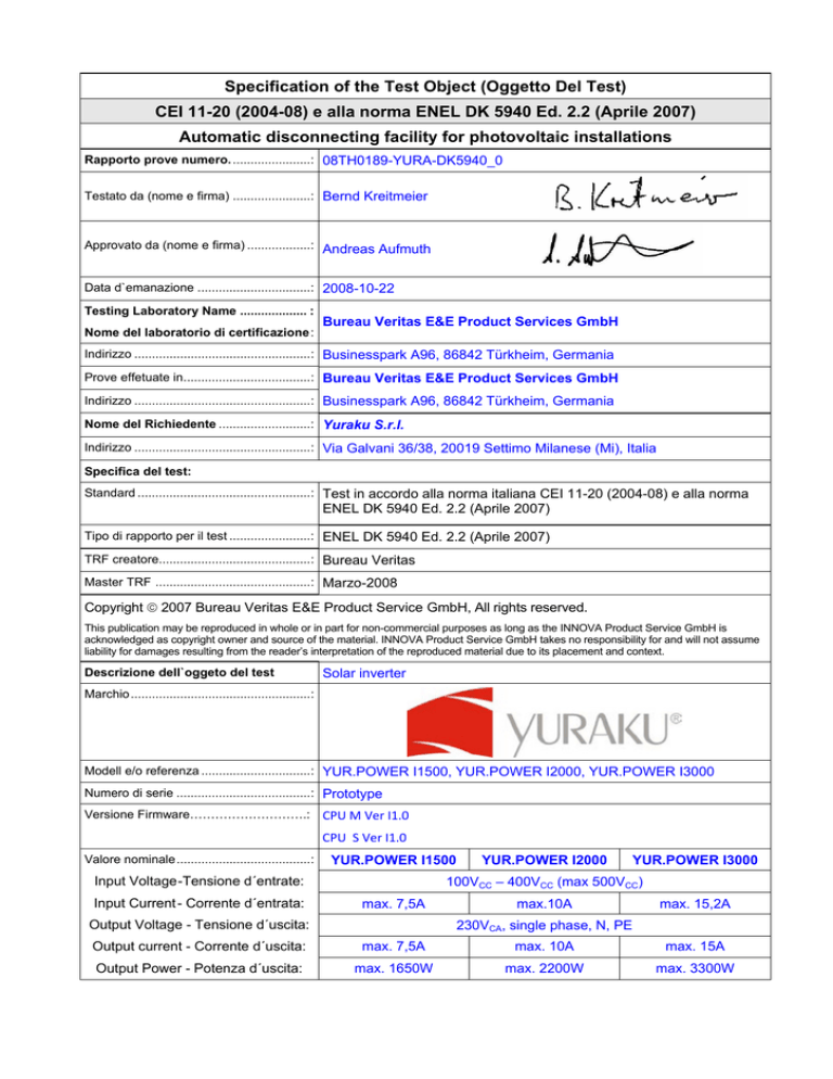
Specification of the Test Object (Oggetto Del Test)
CEI 11-20 (2004-08) e alla norma ENEL DK 5940 Ed. 2.2 (Aprile 2007)
Automatic disconnecting facility for photovoltaic installations
Rapporto prove numero. ......................: 08TH0189-YURA-DK5940_0
Testato da (nome e firma) ......................: Bernd Kreitmeier
Approvato da (nome e firma) ..................: Andreas Aufmuth
Data d`emanazione ................................: 2008-10-22
Testing Laboratory Name ................... :
Nome del laboratorio di certificazione :
Bureau Veritas E&E Product Services GmbH
Indirizzo ..................................................: Businesspark A96, 86842 Türkheim, Germania
Prove effetuate in....................................: Bureau Veritas E&E Product Services GmbH
Indirizzo ..................................................: Businesspark A96, 86842 Türkheim, Germania
Nome del Richiedente ..........................: Yuraku S.r.l.
Indirizzo ..................................................: Via Galvani 36/38, 20019 Settimo Milanese (Mi), Italia
Specifica del test:
Standard .................................................: Test in accordo alla norma italiana CEI 11-20 (2004-08) e alla norma
ENEL DK 5940 Ed. 2.2 (Aprile 2007)
Tipo di rapporto per il test .......................: ENEL DK 5940 Ed. 2.2 (Aprile 2007)
TRF creatore...........................................: Bureau Veritas
Master TRF ............................................: Marzo-2008
Copyright © 2007 Bureau Veritas E&E Product Service GmbH, All rights reserved.
This publication may be reproduced in whole or in part for non-commercial purposes as long as the INNOVA Product Service GmbH is
acknowledged as copyright owner and source of the material. INNOVA Product Service GmbH takes no responsibility for and will not assume
liability for damages resulting from the reader’s interpretation of the reproduced material due to its placement and context.
Descrizione dell`oggeto del test
Solar inverter
Marchio ...................................................:
Modell e/o referenza ...............................: YUR.POWER I1500, YUR.POWER I2000, YUR.POWER I3000
Numero di serie ......................................: Prototype
Versione Firmware……………………….: CPU M Ver I1.0 CPU S Ver I1.0
Valore nominale......................................:
YUR.POWER I1500
Input Voltage -Tensione d´entrate:
Input Current - Corrente d´entrata:
YUR.POWER I2000
YUR.POWER I3000
100VCC – 400VCC (max 500VCC)
max. 7,5A
Output Voltage - Tensione d´uscita:
max.10A
max. 15,2A
230VCA, single phase, N, PE
Output current - Corrente d´uscita:
max. 7,5A
max. 10A
max. 15A
Output Power - Potenza d´uscita:
max. 1650W
max. 2200W
max. 3300W
Page 2 of 49
Report No.: 08TH0189-YURA-DK5940_0
Copy of marking plate:
Copia della piastra della marcatura:
In addition the applicants name and serial number will be added to the label.
Page 3 of 49
Display front:
Report No.: 08TH0189-YURA-DK5940_0
Page 4 of 49
Bernd Kreitmeier
Report No.: 08TH0189-YURA-DK5940_0
History Sheet
Storico del foglio
2008-10-22
Initial report was written
Address of the manufacturer sites:
Indirizzo dello stabilimento di produzione:
Powercom Co., Ltd.
8F, NO. 246, Lien Chen Road,
Chung Ho City
Taipei Hsien,
Taiwan, R.O.C.
Rev. 0
Page 5 of 49
Report No.: 08TH0189-YURA-DK5940_0
Particulars: test item vs. test requirements / Dettagli: oggetto del test vs requisti del test
Equipment mobility ..................................... :
mobilità dell'apparecchiatura....................... :
Operating condition ..................................... :
Modo d´ operazione .................................... :
For building-in
Continuous
Mains supply tolerance (%)......................... : Input (Solar): 100-500VDC
Tolleranza dell’alimentatore principale
:
Output (mains): 230VAC
Class of equipment ..................................... :
Classe del dispositivo.................................. :
Mass of equipment (kg)............................... :
Peso del dispositivo..................................... :
Protection against ingress of water ............ :
Grado di protezione contro l’acqua ............. :
Class I
14kg
IP65 according to EN 60529
Test case verdicts / Risultati dei test
Test case does not apply to the test object :
Il test non si applica all’oggetto del test....... :
Test item does meet the requirement ........ :
Il test rispetta il requisito.............................. :
Test item does not meet the requirement .. :
Il test non rispetta il requisito....................... :
N/A
P(ass)
F(ail)
Test:
Date of receipt of test item ……… ........... :
Data di Ricezione del test .......................... :
Date(s) of performance of test ................ :
Data(e) di esecuzione del test..................... :
2008-08-28
WW 35 to WW 37
Page 6 of 49
Report No.: 08TH0189-YURA-DK5940_0
General remarks:
The
test
result
presented
in
this
report
relate
only
to
the
object(s)
This report shall not be reproduced, except in full, without the written approval of the applicant.
tested.
”(see Enclosure #)" refers to additional information appended to the report.
"(see appended table)" refers to a table appended to the report.
Throughout this report a comma (point) is used as the decimal separator.
Il risultato del test presentato in questo report, si relaziona solo all’oggetto testato. Questo report non puo
essere riprodotto in parte, senza l’autorizzazione del produttore.
(vedi nota #) si riferisce a informazioni aggiuntive aggiunte al report
(vedi tabella allegata) si riferisce ad una tabella allegata
In tutto il report come separatore decimale si è usata la virgola.
This Test Report consists of the following documents:
1.
2.
3.
4.
5.
6.
7.
Test Report
Annex 1 – ISO certificate
Annex 2 – EMC Test Report
Annex 3 – Datasheet of the relays
Annex 4 – Schematics
Annex 5 – Pictures of the units
Annex 6 – Test equipment
Page 7 of 49
Report No.: 08TH0189-YURA-DK5940_0
General product information: / Informazione generali sul prodotto:
The Solar converter converts DC voltage into AC voltage.
The input and output are protected by capacitors and varistors to earth. The unit is providing EMC filtering at
the input and output towards mains. The unit does not provide galvanic separation from input to output but
provides a RCMU and an insulation measurement DC – PE. The output is switched off by two independent
relays in series to assure, that the output circuit will also operate in case of one error. The whole control
system is build up redundant.
Il convertitore solare permette la conversione della tensione continua (DC) in tensione alternata (AC)
L’ingresso e l’uscita sono protetti da variatori connessi a terra. L’unitá è provvista di un filtro EMC all’uscita
verso i principale le condutture. L’unità non fornisce una separazione galvanica dall’entrata all’uscita. L’uscita
è disattivata da due relay indipendenti posti in serie per assicurare che l’apertura del circuito di uscita operi
anche in caso di un errore.
Page 8 of 49
Report No.: 08TH0189-YURA-DK5940_0
TEST SHEET:
C4.1 CEI 11-20 V1, 5: Criteria of connection to the public network
( CEI 11-20 V1, 5: Criteri di collegamento alla rete pubblica)
C4.1.1 CEI 11-20 V1, 5.1: Production installations in Cat I networks – Power Factor
(CEI 11-20 V1, 5.1:Funzionamento in parallelo alla rete pubblica di I categoria –
Fattore di Potenza)
Power factor test
(Fattore di potenza)
Operating conditions:
(Condizioni di
funzionamento)
Grid voltage:
Output
(V)
Power: (%)
P
Power factor:
(Factor di potenza)
Measurement:
(Misurazione) [1]
Reactive Power:
(Potenza reattiva)
Measurement:
(Misurazione)
(kvar)
Limiting value:
(Valore limite)
(Kvar)
YUR.POWER I1500
230V
230V
230V
230V
100% PN
50% PN
20% PN
10% PN
0,995
0,990
0,958
0,899
0,171
0,137
0,107
0,092
1,0
1,0
1,0
1,0
0,198
0,156
0,113
0,106
1,0
1,0
1,0
1,0
0,183
0,144
0,124
0,093
1,0
1,0
1,0
1,0
YUR.POWER I2000
230V
230V
230V
230V
100% PN
50% PN
20% PN
10% PN
0,996
0,989
0,962
0,886
230V
230V
230V
230V
100% PN
50% PN
20% PN
10% PN
0,998
0,955
0,988
0,957
YUR.POWER I3000
Limits of CEI 11-20 V1, Section 5.1
Page 9 of 49
Report No.: 08TH0189-YURA-DK5940_0
8. Protection against DC components in the output current
( 8. Criteri generali di allacciamento)
Protection against DC-Injection, IDC<0,5% of Imax, within max. 0,1s
(Protezione corrente continua, 0,5% della corrente massima, max. 0,1 s)
Grid voltage:
(Vac)
Idc polarity
(Polarita c.c.)
230V
230V
+
-
230V
230V
+
-
Measurement:
(Misurazione)
(mA)
P
Limiting value:
(Valore limite)
(mA)
Disconnection time
(Tempo de
intervento)
+32,5mA
-32,5mA
90ms
93ms
+43,5mA
-43,5mA
83ms
87ms
+75,0mA
-75,0mA
79ms
90ms
YUR.POWER I1500
+14mA
-14mA
YUR.POWER I2000
+11mA
-12mA
YUR.POWER I3000
230V
230V
+
-
+15mA
-12mA
Limits of DK5940 Ed. 2.2, Allegato AIB 2.3.1.1
YUR.POWER I1500
2,00E+03
3,50E-02
1,80E+03
2,50E-02
1,60E+03
Power
1,20E+03
5,00E-03
1,00E+03
-5,00E-03
8,00E+02
6,00E+02
-1,50E-02
4,00E+02
-2,50E-02
2,00E+02
0,00E+00
-3,50E-02
1
73 145 217 289 361 433 505 577 649 721 793 865 937 10091081115312251297136914411513158516571729
Time
DC-Injection
1,50E-02
1,40E+03
Page 10 of 49
Report No.: 08TH0189-YURA-DK5940_0
YUR.POWER I2000
3,E+03
0,050
0,040
2,E+03
0,030
0,020
0,010
power (W)
2,E+03
0,000
1,E+03
-0,010
-0,020
5,E+02
-0,030
-0,040
0,E+00
-0,050
1
71
141 211 281 351 421 491 561 631 701 771 841 911 981 1051 1121 1191 1261 1331 1401 1471 1541 1611 1681 1751
time (500ms cycle)
P1
IDC1
max. DC
max. DC
YUR.POWER I3000
4,E+03
0,100
0,080
3,E+03
0,060
power (W)
3,E+03
0,040
0,020
2,E+03
0,000
2,E+03
-0,020
-0,040
1,E+03
-0,060
5,E+02
-0,080
0,E+00
-0,100
1
76
151 226 301 376 451 526 601 676 751 826 901 976 1051 1126 1201 1276 1351 1426 1501 1576 1651 1726 1801 1876
time (500ms cycle)
P1
IDC1
max. DC
max. DC
Page 11 of 49
Report No.: 08TH0189-YURA-DK5940_0
9.4 Automatic protection –test results
(Protezioni di interfaccia – risultati di prova)
9.5 Massima tensione e minima tensione
Condizioni di
funzionamento:
P
Frequenza: 50Hz
Protezioni minima tensione
Parametro
Valore limite
Voltaggio
0,8 UN
(184 VAC)
188,2V
195 -> 185V
230 -> 185V
Tempo di intervento (ms)
<= 200
Valore misurato
80ms
73ms
Tempo di
sconnessione
75ms
69ms
Tempo di
≥ 5s
35s
riconnessione
Note:
Limits of DK 5940, ED. 2.2 (Aprile 2007), Table 3
71ms
72ms
Protezioni massima tensione
Voltaggio
1,2 UN
(276 VAC)
271,5
269 -> 279V
230 -> 279V
≥ 5s
Tempo di intervento (ms)
<= 100
89ms
75ms
72ms
85ms
35s
84ms
84ms
Page 12 of 49
Report No.: 08TH0189-YURA-DK5940_0
9.5 Massima frequenza e minima frequenza
Condizioni di
funzionamento:
Qualunque livello di potere di uscita
Protezioni minima frequenza
Parametro
voltaggio di
uscita
Valore limite
Valore misurato
P
Frequenza
(Hz)
Tempo di intervento
(ms)
80%UN
49,7
UN
Protezioni massima frequenza
Frequenza
(Hz)
120%UN
senza ritardo intenzionale
49,80H
49,80H
49,80Hz
z
z
Tempo di
50,00 →
senza ritardo intenzionale
sconnessione
49,00
Tempo di
≥ 5s
35s
riconnessione
Note:
Limits of DK 5940, ED. 2.2 (Aprile 2007), Table 2
Tempo di intervento
(ms)
80%UN
50.3
UN
120%UN
senza ritardo intenzionale
50,20H
50,20Hz
50,20Hz
z
50,00 →
51,00
senza ritardo intenzionale
≥ 5s
35s
Page 13 of 49
Report No.: 08TH0189-YURA-DK5940_0
9.5 Frequency derivative (Rate of Change of Frequency) test
(Derivata di frequenza)
Frequency derivative protection –Frequency variation = + 0,5Hz/s
(increasing)
(Protezioni derivata di frequenza, , valore d'intervento 50,3Hz)
Operating conditions:
(Condizioni di funzionamento)
Grid voltage:
Power:
(V)
(%)
230V
230V
230V
N/A
Disconnection time:
(Tempo di intervento)
Measurement: Measurement: Limiting value:
(Valore limite)
(Misurazione)
(Misurazione)
(s)
(ms)
(Hz)
senza ritardo
intenzionale
(10% PN)
(50% PN)
(100% PN)
Limits of DK 5940 Ed. 2.2 (Aprile 2007), Table 2
Frequency derivative protection –Frequency variation = - 0,5Hz/s
(decreasing)
(Protezioni derivata di frequenza, valore d'intervento 49,7Hz)
Operating conditions:
(Condizioni di funzionamento)
Grid voltage:
Power:
(V)
(%)
230V
230V
230V
(10% PN)
(50% PN)
(100% PN)
Limits of DK 5940 Ed. 2.2 (Aprile 2007), Table 2
N/A
Disconnection time:
(Tempo di intervento)
Measurement: Measurement: Limiting value:
(Valore limite)
(Misurazione)
(Misurazione)
(s)
(ms)
(Hz)
senza ritardo
intenzionale
Page 14 of 49
Report No.: 08TH0189-YURA-DK5940_0
9.2.1 Sigillatura del sistema di misura dell’energia prodotta ed incentivata
(Sealing of the system to protect against misuse)
Page 15 of 49
Report No.: 08TH0189-YURA-DK5940_0
ALLEGATO AIB:
APPARECCHIATURE DI INTERFACCIA CON LA RETE BT
2.1.3 Verifiche
Auto Test Function
In “Working Mode” press the button over 3sec. The LCD will show “Setting”. Than the PV
inverter will enter “Function Setting Mode”, after that toggle the button, you will see the
following setting items:
Contrast Set
Language Set
Auto Test Set
When you see the “Auto Test Set”, press the button over 3seconds, LCD will show
“Setting” then PV inverter will start “Auto Test Procedure”.
During the “Auto Test Procedure”, if user press button over 3 seconds, LCD will show
“Escape Auto Test” then PV inverter will finish “Auto Test Procedure”
The “Auto Test Procedure” start with the over voltage from 270V to 229V. After this step
the relays are opened. On LCD will show “OK 229V – 0,05S”. At next step the PV inverter
will start with the under voltage from 190V to 230V. The Relays are opened. The result
was show on LCD “OK 230V – 0,05S”. In the following step the test will start with upper
and lower frequency check. After the test the relays are opened and the result was show
on LCD “OK 49,9Hz – 0,05S” (upper frequency) and “OK 50Hz – 0,05S” (lower frequency).
The summary result will show on LCD “Test Pass”.
During the “Auto Test Procedure” the PV inverter will not supply with current into the grid.
Page 16 of 49
Report No.: 08TH0189-YURA-DK5940_0
3.1 Protezione di interfaccia (PIB)
Rigidità dielettrica
Location
Relay RY 1/RY 2 (SONG CHUAN
PRECISION CO., LTD. /SCL-1-HDPNO-F 12VDC)
AC to PE
DC to PE
P
2kV c.a.
Tensione di prova
Breakdown Yes/No
No
2kV c.a.
2kV c.a.
No
No
Prova ad impulso
Location
Relay RY 1 (SONG CHUAN
PRECISION CO., LTD. / SCL-1-HDPNO-F 12VDC)
Relay RY 2 (SONG CHUAN
PRECISION CO., LTD. / SCL-1-HDPNO-F 12VDC)
P
Tensione di prova
1,2/50µs surge impulse
2kV CM
Breakdown Yes/No
No
1kV DM
No
Misura della resistenza di isolamanti
Location
Relay RY 1/RY 2 (SONG CHUAN
PRECISION CO., LTD. /.SCL-1-HDPNO-F 12VDC)
Tensione di prova
500V c.c.
100MOhm
Prove di assestamento
Temperatura
55°C
40°C
-10°C
-10°C -> +40°C
Note: No effect on the unit
Umidita relativa
50%
93%
10%
---
P
Durata
16h
4 giorni
10h
3h @ -10°C, 3h @ +40°C
Umidita relativa
50%
93%
-----
P
Durata
16h
4 giorni
10h
3h @ -10°C, 3h @ +40°C
Prove ad apparato funzionante
Temperatura
55°C
40°C
-10°C
-10°C -> +40°C
Note: The inverter was running.
P
Resistenza di
isolamenti
>150MOhm
Limite
Prove di sovraccaricabilità dei circuti voltmetrici di misura
Tensione
≥130%UN
≥200%UN
Durata
permanente
1s
P
P
P
Page 17 of 49
Annex 1
ISO certificate
Report No.: 08TH0189-YURA-DK5940_0
Page 18 of 49
Report No.: 08TH0189-YURA-DK5940_0
Page 19 of 49
Report No.: 08TH0189-YURA-DK5940_0
Page 20 of 49
Report No.: 08TH0189-YURA-DK5940_0
Annex 2
EMC Report
The whole report is stored by Bureau Veritas E&E Product Services
Türkheim
Germany
The test was performed with the OEM model SLK-X000 but is also valid for the YURAKU series since
it is the same hard- and software
Page 21 of 49
Report No.: 08TH0189-YURA-DK5940_0
Page 22 of 49
Report No.: 08TH0189-YURA-DK5940_0
Page 23 of 49
Report No.: 08TH0189-YURA-DK5940_0
Page 24 of 49
Annex 3
Datasheet of the relays
Report No.: 08TH0189-YURA-DK5940_0
Page 25 of 49
Report No.: 08TH0189-YURA-DK5940_0
Page 26 of 49
Report No.: 08TH0189-YURA-DK5940_0
Page 27 of 49
Report No.: 08TH0189-YURA-DK5940_0
Page 28 of 49
Report No.: 08TH0189-YURA-DK5940_0
Page 29 of 49
Report No.: 08TH0189-YURA-DK5940_0
Page 30 of 49
Report No.: 08TH0189-YURA-DK5940_0
Page 31 of 49
Report No.: 08TH0189-YURA-DK5940_0
Page 32 of 49
Report No.: 08TH0189-YURA-DK5940_0
Page 33 of 49
Report No.: 08TH0189-YURA-DK5940_0
Page 34 of 49
Report No.: 08TH0189-YURA-DK5940_0
Page 35 of 49
Report No.: 08TH0189-YURA-DK5940_0
Page 36 of 49
Report No.: 08TH0189-YURA-DK5940_0
Page 37 of 49
Report No.: 08TH0189-YURA-DK5940_0
Page 38 of 49
Annex 4
Schematics
Report No.: 08TH0189-YURA-DK5940_0
Page 39 of 49
Report No.: 08TH0189-YURA-DK5940_0
Page 40 of 49
Report No.: 08TH0189-YURA-DK5940_0
Page 41 of 49
Report No.: 08TH0189-YURA-DK5940_0
Page 42 of 49
Report No.: 08TH0189-YURA-DK5940_0
Page 43 of 49
Report No.: 08TH0189-YURA-DK5940_0
Page 44 of 49
Annex 5
Pictures of the unit
Report No.: 08TH0189-YURA-DK5940_0
Page 45 of 49
Report No.: 08TH0189-YURA-DK5940_0
Display
YUR.POWER I1500 (identical YUR.POWER I2000)
YUR.POWER I3000
Page 46 of 49
Report No.: 08TH0189-YURA-DK5940_0
Connecting Plate
AC Connector
DC-Connector
Main Switch
Page 47 of 49
Report No.: 08TH0189-YURA-DK5940_0
Left side (Yuraku is red colored)
Right side (Yuraku is red colored)
Rear side
Page 48 of 49
Annex 6
Test Equipment list
Report No.: 08TH0189-YURA-DK5940_0
Page 49 of 49
Gerät
Intern Hersteller
e Nr.
Report No.: 08TH0189-YURA-DK5940_0
Type
Serien Nr.
Schwingkreis
336
GRS
-
-
Letzte
Kalibrierun
g
-
Nächste
Kalibrierun
g
-
Dielectric
tester
26
ET Euro-Test
EHV10SL
00.09.4189
Jun 2008
Jun 2009
DMM
89
Gossen - Metrawatt 24S
LB0735
Apr 2008
Apr 2009
Current Clamp
110
Chauvin Arnoux
YPAC12
118609YDV
Mai 2008
Mai 2009
Power Station
277
Power Control
JP13kW/90015
pe
0305/39476
-
Klimaschrank
279
CTS GmbH
C-40/200
052027
Mai 2005
Feb 2006
AC Source
323
Chroma
6590
0225
-
-
Digital
osciloscop
324
Yokogawa
DL1620
91EB06225
Apr 2008
Apr 2009
Power Meter
335
Zimmer
LMG 500-3
00940605
Aug 2008
Aug 2009
Variable
Resistor
397
Ruhstrat
59Ω 2,5A
-
-
-
3-Phasen
Trenntrafo
446
Statron
5316.1
9507001
-
-

