DIGITALI
DIGITAL METERS
Indicatore digitale di
tensione continua
96x96 mm
Misura di tensione continua bidirezionale
Misura di corrente continua bidirezionale,
da shunt esterno(mV)
Visualizzazione di qualsiasi grandezza
direttamente proporzionale
Ingresso 60mV – 500V
Ingresso per segnali standard 1 - 5 - 10V
DG9K
Direct voltage
digital meter
96x96 mm
Bidirectional direct voltage measurements
Bidirectional direct current measurements,
by external shunt (mV)
Display any proportional
process variable
Input 60mV – 500V
Input for standard signal 1 - 5 - 10V
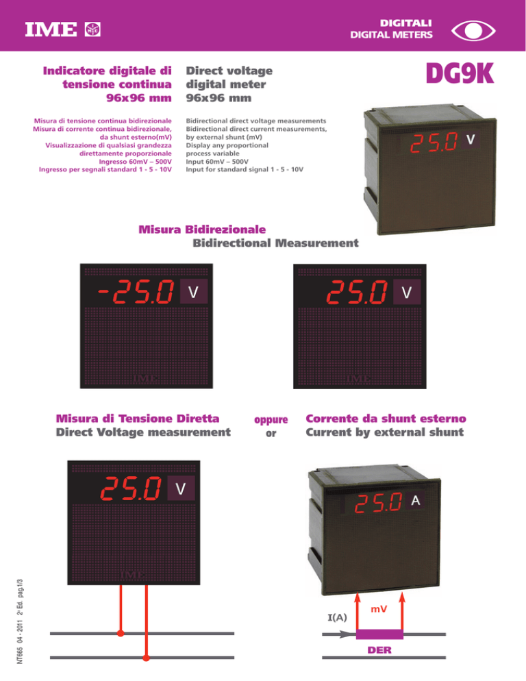
Misura Bidirezionale
Bidirectional Measurement
NT665 04 - 2011 2a Ed. pag.1/3
Misura di Tensione Diretta
Direct Voltage measurement
oppure
or
Corrente da shunt esterno
Current by external shunt
I(A)
mV
DER
CODICE DI ORDINAZIONE
ORDERING CODE
INGRESSO
INPUT
VISUALIZZAZIONE
DISPLAY
DG9K05N7
-100...0...100V
-99,9...0...99,9V
DG9K05N9
-500...0...500V
-500...0...500V
DG9K05NB
-1...0...1V
DG9K05ND
-5...0...5V
DG9K05NF
-10...0...10V
DG9K05NM
-60...0...60mV
-100...0...100mV
DG9K05NS
- 150...0...150mV
DG9K01N7
-100...0...100V
-99,9...0...99,9V
DG9K01N9
-500...0...500V
-500...0...500V
DG9K01NB
-1...0...1V
-5...0...5V
DG9K01NF
-10...0...10V
DG9K01NM
-60...0...60mV
-100...0...100mV
DG9K01NS
- 150...0...150mV
DG9K07N7
-100...0...100V
-99,9...0...99,9V
DG9K07N9
-500...0...500V
-500...0...500V
DG9K07NB
-1...0...1V
-5...0...5V
DG9K07NF
-10...0...10V
-60...0...60mV
DG9K07NO
-100...0...100mV
DG9K07NS
- 150...0...150mV
DG9K01N7
-100...0...100V
-99,9...0...99,9V
-500...0...500V
DG9K0HN9
-500...0...500V
-1...0...1V
DG9K0HND
-5...0...5V
DG9K0HNF
-10...0...10V
DG9K0HNM
-60...0...60mV
DG9K0HNO
-100...0...100mV
DG9K0HNS
- 150...0...150mV
-
24V
-
240V
-
48V
20...150V
a richiesta
on request
Accessorio protezione frontale IP54 / IP54 front frame protection kit
VISUALIZZAZIONE
DISPLAY
Tipo display: LED rossi, 7 segmenti
Type of display: 7 segments, red LED’s
Altezza cifre: 14mm
Digit height: 14mm
N° punti visualizzazione: 1.000 (3 cifre)
N° of display points: 1.000 (3 digit)
Indicazione massima: -999...999
Maximum display: -999...999
Indicazione polarità: automatica, visualizzazione segno “-”
Polarity indication: automatic, signal “-”
Unità ingegneristica: a richiesta
Engineering unit: on request
Punto decimale: fisso
Decimal point: fixed
Indicazione fuoriscala: accensione LED rosso
Overrange indication: red LED on
Fuoriscala: visualizzazione > 999
Overrange: display > 999
Risoluzione: 1 digit
Resolution: 1 digit
Precisione (riferita al fondo scala): ± 0,5% + 1 digit
Accuracy (referred to full scale): ± 0,5% + 1 digit
Aggiornamento lettura: 3 letture/secondo
Display update: 3 reading/second
INGRESSO
INPUT
Inserzione: diretta
Connection: direct
Tensione nominale Un: 60mV...500V
Rated voltage Un: 60mV...500V
Campo di misura: -Un...0...Un
Measuring range: -Un...0...Un
Impedenza di ingresso: 10MΩ (Un < 2V) - ≥ 300kΩ (Un ≤ 100V) - ≥ 900kΩ (Un > 100V)
Input impedance: 10MΩ (Un < 2V) - ≥ 300kΩ (Un ≤ 100V) - ≥ 900kΩ (Un > 100V)
Sovraccarico permanente: 1,2Un (massimo 650V)
Continuous overload: 1,2Un (max. 650V)
Sovraccarico istantaneo: 2Un/5s (massimo 650V)
Instantaneous overload: 2Un/5s (max. 650V)
NT665 04 - 2011 2a Ed. pag.2/3
ADGIP549
115 + 230V
a richiesta
on request
DG9K07NM
DG9K0HNB
cc /dc
a richiesta
on request
DG9K01NO
DG9K07ND
ca / ac
a richiesta
on request
DG9K05NO
DG9K01ND
AL. AUSILIARIA
AUX. SUPPLY
La I.M.E. S.p.A. si riserva in qualsiasi momento, di modificare le caratteristiche tecniche senza darne preavviso. / I.M.E. S.p.A. reserves the right, to modify the technical characteristics without notice.
ALIMENTAZIONE AUSILIARIA
AUXILIARY SUPPLY
Valore nominale Uaux ca: 24 – 48 – 115 – 230 – 240V
Rated value Uaux ac: 24 – 48 – 115 – 230 – 240V
Variazione ammessa: ±10% Uaux ca – 40...60V (Uaux 48V)
Tolerance: ±10% Uaux ca – 40...60V (Uaux 48V)
Frequenza nominale: ± 50%Hz
Rated frequency: ± 50%Hz
Frequenza di funzionamento: 47...63Hz
Working frequency: 47...63Hz
Autoconsumo: ≤ 4,5VA
Rated burden: ≤ 4,5VA
Valore nominale Uaux cc: 20...150Vcc
Rated value Uaux dc: 20...150Vdc
Autoconsumo: ≤ 3W
Rated burden: ≤ 2,5W
Protezione contro l’inversione di polarità
Protected against incorrect polarity
ISOLAMENTO
(EN/IEC 61010-1)
Categoria di installazione: III
Installation category: III
Grado di inquinamento: 2
Pollution degree: 2
Prova di tensione alternata 2kV valore efficace 50Hz/1 min
A.C. voltage test 2kV r.m.s. 50Hz/1 min
Circuiti considerati: misura, alimentazione
Considered circuits: measure, supply
Prova di tensione alternata 4kV valore efficace 50Hz/1 min
A.C. voltage test 4kV r.m.s. 50Hz/1 min
Circuiti considerati: tutti i circuiti e massa
Considered circuits: all circuits and earth
COMPATIBILITA’ ELETTROMAGNETICA
ELECTROMAGNETIC COMPATIBILITY
Prove di emissione in accordo con EN/IEC 61326-1
Emission tests according to EN/IEC 61326-1
Prove di immunità in accordo con EN/IEC 61326-1
Immunity tests according to EN/IEC 61326-1
CONDIZIONI AMBIENTALI
ENVIRONMENTAL CONDITIONS
Temperatura di riferimento: 23°C ±1°C
Reference temperature: 23°C ±1°C
Temperatura di impiego: -5...55°C
Specified operating range: -5...55°C
Variazione indice di classe: ±0,03%/°C
Variation to the class index: ±0,03%/°C
Campo limite per l’immagazzinamento e trasporto: -40...70°C
Limit range for storage and transport: -40...70°C
Adatto all’utilizzo in clima tropicale
Suitable for tropical climates
Massima potenza dissipata1: ≤ 4W
Max. power dissipation1: ≤ 4W
For switchboard thermal calculation
1
1
CUSTODIA
HOUSING
Custodia: incasso (foratura pannello 92x92mm)
Housing: flush mounting (panel cutout 92x92mm)
Frontale: 96x96mm (99x99mm con protezione IP54)
Front frame. 96x96mm (99x99mm with IP54 protection)
Profondità: 103mm
Depth: 103mm
Connessione: faston 6,3x0,8mm
Connections: faston 6,3x0,8mm
Materiale custodia: policarbonato autoestinguente
Housing material: self-extinguishing policarbonate
Grado di protezione (EN/IEC 60529): IP50 (frontale) IP20 (morsetti)
Protection degree (EN/IEC 60529): IP50 (front frame) IP20 (terminals)
Opzione: protezione frontale IP54 (con accessorio ADGIP549)
Option: IP54 protection degree (wih kit ADGIP549)
Peso: 320 grammi
Weight: 320 grams
Per il dimensionamento termico dei quadri
SCHEMA D’INSERZIONE
WIRING DIAGRAM
S 305/67
INPUT
DIMENSIONI
NT665 04 - 2011 2a Ed. pag.3/3
INSULATION
(EN/IEC 61010-1)
(+)
(–)
AUX. SUPPLY
c l h
(–)
(+)
14
15
12 13 20
DIMENSIONS
99
99 96
92
92
96
103
11

