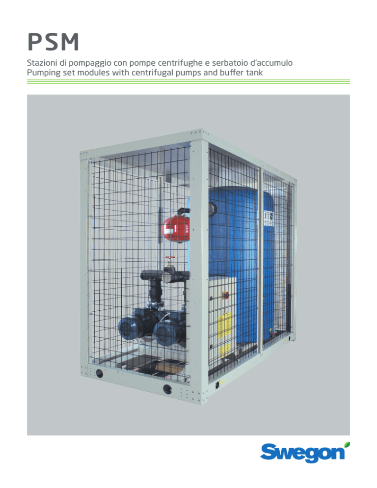
PSM
Stazioni di pompaggio con pompe centrifughe e serbatoio d’accumulo
Pumping set modules with centrifugal pumps and buffer tank
indice
Generalita’
Caratteristiche tecniche
Accessori
La serie
Campo di applicazione
Generalita’
Ispezione, trasporto e posizionamento
Ispezione
Sollevamento e trasporto
Disimballaggio
Posizionamento
Installazione
Spazi di installazione
Raccomandazioni generali per i collegamenti idraulici
Collegamenti elettrici
Generalita’
Collegamenti elettrici dell’unità
Consensi esterni
Avviamento
Controlli preliminari
Messa in funzione
Arresto del gruppo
Limiti di funzionamento
Manutenzione e controlli periodici
Avvertenze
Generalità
Messa fuori servizio dell’unita’
Ricerca guasti
Disegni di ingombro
Schema circuito idraulico
Dati tecnici
Prevalenze utili
1476
1476
1476
1477
1477
1477
1478
1478
1479
1480
1481
1482
1484
1484
1485
1485
1486
1486
1486
1487
1488
1488
1488
1489
1489
1490
1494
1496
1497
GENERALITA'
GENERAL
DESCRIPTION
CARATTERISTICHE
TECNICHE
TECHNICAL
FEATURES
1476
Stazioni di pompaggio con pompe
centrifughe, serbatoio di accumulo e
vaso di espansione per impianti idraulici di raffreddamento e riscaldamento.
Pumping set modules with centrifugal
pumps, buffer tank and expansion vessel for cooling and heating hydraulic
plants.
Stazioni di pompaggio PSM
Pumping set modules PSM
STRUTTURA
a telaio portante e pannellature asportabili, (esclusi i modelli 380-680-9201100 che sono forniti con griglie metalliche) è realizzata in lamiera zincata
ulteriormente verniciata con polveri
poliestere a 180 °C, che le conferiscono un’alta resistenza agli agenti atmosferici. Viteria in acciaio inox.
UNIT FRAME
Self supporting frame with removable
panels (models 380-680-920-1100 excluded, as supplied with metallic grilles) made of galvanized steel protected
with polyesthere powder painting
baked enamel which allows the unit to
be installed outdoor.Stainless steel
screws and bolts.
ELETTROPOMPE
Due elettropompe centrifughe monoblocco con accoppiamento diretto motore-pompa tramite unico albero in acciaio al cromo. Corpo e girante in ghisa, tenuta meccanica, motore elettrico
a 2 poli trifase con grado di protezione elettrica IP 54.
Le due elettropompe disposte in parallelo,funzionano alternativamente.
Disponibile a richiesta la versione con
pompa singola.
PUMPS
Two cenrtifugal pumps directly coupled with the electric motor by extended chrome steel shaft,. Cast iron
pump casing and impeller, mechanical
seal, 2 pole three-phase motor, IP 54
protection.
The two pumps are installed in parallel
and one is stand-by.
On request, the version with single
pump is available.
SERBATOIO
Serbatoio in lamiera zincata con coibentazione in poliuretano espanso rivestito in PVC.
STORAGE TANK
Foamed poyurethan insulated storage
tank, PVC coated.
CIRCUITO IDRAULICO
Circuito idraulico interno costituito da
tubi in gomma flessibili o acciaio, raccorderia in acciaio, valvole di ritegno,
saracinesche, valvole di sfiato, vaso di
espansione.
HYDRAULIC CIRCUIT
Hydraulic circuit composed with flexible rubber tubes, steel pipe fittings,
check valves, gate valves, vent valves
and expansion vessel.
QUADRO ELETTRICO
Il quadro elettrico con grado protezione IP 55 comprende:
- sezionatore generale
- interruttori magnetotermici delle
pompe
- teleruttori delle pompe
- selettore-interruttore di marcia delle
pompe
ELECTRIC SWITCH BOARD
According to IP 55 it includes :
ACCESSORI:
ACCESSORIES:
• Resistenza elettrica serbatoio
• Resistenza elettrica antigelo per le
pompe
• Versione con pompa singola
• Gruppo di caricamento automatico
dell’acqua
• Valvola di sicurezza
• Manometri
• Antivibranti in gomma od a molla
• Alimentazione elettrica con differenti
tensioni o frequenze
• Predisposizione per funzionamento
con fluidi a basse temperature (speciale tenuta meccanica delle pompe).
•
•
•
•
•
•
•
•
-
main switch
pump circuit breakers
pump contactors
pump selector switch
Tank electric heater
No frost electric heater for pumps
Single pump version
Automatic water filling kit
Safety valve
Water pressure gauges
Rubber or spring antivibration mounts
Electric supply with different voltages
or frequencies
• Provision for operation with low temperature fluids (pump’ special mechanical seal)
LA SERIE
THE SERIES
La serie di stazioni di pompaggio PSM è
disponibile in varie grandezze con portate e prevalenze che variano da modello a modello (si vedano le tabelle dei
dati tecnici).
Pumping set module PSM series is available in various sizes with water flow
and available static pressure varyng for
each model (see technical data sheets).
CAMPO DI APPLICAZIONE
APPLICATION FIELD
Queste unità sono destinate alla circolazione ed all’accumulo di acqua nei circuiti idraulici di riscaldamento e raffreddamento.
Il loro utilizzo è raccomandato entro i limiti di funzionamento riportati nel capitolo 5 di questo manuale.
These units have been designed for circulating and storing water in heating or
cooling hydraulic circuits.
Their recommended operation range is
reported in chapter 5 of this manual.
1. GENERALITA’
1. GENERALITY
- All’atto dell’installazione o quando si
debba intervenire sull’unità, è necessario attenersi scrupolosamente alle
norme riportate su questo manuale,
osservare le indicazioni a bordo unità
e comunque applicare tutte le precauzioni del caso.
- When installing or servicing the unit,
it is necessary to strictly follow the recommendations reported on this manual, to conform to all the specifications of the labels on the unit, and to
take any possible precautions of the
case.
- Le pressioni presenti nel circuito
idraulico ed i componenti elettrici presenti possono creare situazioni rischiose durante gli interventi di installazione e manutenzione.
- Pressure in the hydraulic circuit and
electrical equipment present in the
unit can be hazardous when installing
or servicing the unit.
Qualsiasi intervento sull’unità
quindi deve essere effettuato da
personale qualificato.
Therefore every action on the
unit must be done by trained
people only.
- Il mancato rispetto delle norme riportate in questo manuale e qualsiasi
modifica nell’unità non preventivamente autorizzata, provocano l’immediato decadimento della garanzia.
- Not observing the recommendations
reported on this manual, and every
modification to the unit done without
explicit previous authorisation, will
cause the immediate termination of
the warranty.
Att.ne: Prima di effettuare qualsiasi intervento sull’unità, assicurarsi di aver tolto l’alimentazione
elettrica.
Attention: before every operation of servicing on the unit, be
sure that the electric supply is disconnected.
1477
2. ISPEZIONE,
TRASPORTO,
POSIZIONAMENTO
2. INSPECTION,
TRANSPORT,
SITE HANDLING
2.1 ISPEZIONE
2.1 INSPECTION
All’atto del ricevimento dell’unità, verificarne l’integrità: la macchina ha lasciato la fabbrica in perfetto stato;
eventuali danni dovranno essere immediatamente contestati al trasportatore ed annotati sul Foglio di Consegna prima di controfirmarlo. La nostra
Azienda dovrà essere messa al corrente entro 8 giorni sull’entità del danno.
Il Cliente deve compilare un rapporto
scritto concernente ogni eventuale
danno rilevante.
After receiving the unit, immediately
check its integrity. The unit left the
factory in perfect condition; any eventual damage must be questioned to
the carrier and recorded on the Delivery Note before it is signed. Our Company must be informed, within 8 days,
of the extent of the damage.
The Customer should prepare a written statement of any severe damage.
2.2 SOLLEVAMENTO
E TRASPORTO
2.2 LIFTING AND SITE HANDLING
Durante lo scarico ed il posizionamento dell’unità, va posta la massima cura
nell’evitare manovre brusche o violente. I trasporti interni dovranno essere
eseguiti con cura e delicatamente, evitando di usare come punti di forza i
componenti della macchina.
L’unità va sollevata utilizzando tubi in
acciaio infilati negli occhielli contraddistinti da apposita targatura (targhette
gialle a forma di freccia).
Il modulo va sollevato imbracandolo
come indicato nelle figure riportate di
seguito: utilizzare corde o cinghie abbastanza lunghe e barre distanziatrici
per non danneggiare i fianchi ed il coperchio dell’unità.
In alternativa le unità possono essere
sollevate tramite l’ausilio di un carrello
elevatore, infilando le forche di sollevamento nel pallet di appoggio (si veda la figura a pagina seguente).
1478
When unloading the unit, it is highly
recommended to avoid any sudden
move.
When unloading or locating the chiller
with a crane, pass bars through base
frame lifting holes (marked with yellow
arrows) and attach the necessary cable
or chain lifting devices to the bar, ensuring that they are clamped firmly;
protect the sides of the unit with boarding or material of a similar nature.
Another method of lifting is obtained
by using a forklift: fork must be inserted in the base pallet, and care must
be taken in order that the fork does
not hit the section base or panel (see
the following picture).
In any case be sure the method of lifting does not allow the unit to slip
from chains and or slings and allow
the pumping module to turn over or
similar and slide from the lifting devices (see picture at the following page).
Barre distanziatrici
Spacing bars
Protezione fiancate
Protection boarding
Att.ne: In tutte le operazioni di
sollevamento assicurasi di aver
saldamente ancorato l’unità, al
fine di evitare ribaltamenti o cadute accidentali.
Caution: be sure that the method
of lifting does not allow the unit
to slip from chains and slings and
does not allow the unit to turn
over or slide from lifting devices.
2.3 DISIMBALLAGGIO
2.3 UNPACKING
L’imballo dell’unità deve essere rimosso con cura evitando di arrecare possibili danni alla macchina.
I materiali che costituiscono l’imballo
sono di natura diversa. legno, cartone,
nylon ecc.
E’ buona norma conservarli separatamente e consegnarli per lo smaltimento o l’eventuale riciclaggio, alle aziende preposte allo scopo e ridurre così
l’impatto ambientale.
When unpacking the unit pay attention not to damage the unit.
The package is made up by different
materials: wood, paper, nylon etc.
It’s a good rule to keep them separately and deliver to the proper gathering centre in order to reduce their environmental impact.
1479
2.4 POSIZIONAMENTO
2.4 LOCATION
E’ opportuno prestare attenzione ai
punti seguenti per determinare il sito
migliore ove installare l’unità ed i relativi collegamenti:
- dimensioni e provenienza delle tubazioni idrauliche;
- ubicazione dell’alimentazione elettrica;
- accessibilità per le operazioni di manutenzione o riparazione;
Consideration must be given to the
following points when determining the
most suitable site for the equipment
installation:
- location arrangement and size of
water piping;
- electrical power supply;
- accessibility
of
space
for
servicing/maintenance and repair of
the unit and/or its components;
- floor loading strength and ability to
support the operating weight of the
unit;
- possible objection to operating noise.
- solidità del piano di supporto;
- possibile riverbero delle onde sonore.
Tutti i modelli della serie PSM sono
progettati e costruiti per installazioni
esterne.
E’ buona norma creare una soletta di
supporto di dimensioni adeguate a
quelle dell’unità. Tale precauzione risulta indispensabile quando si voglia
collocare l’unità su terreno instabile
(terreni vari, giardini, ecc.).
All PSM series units are designed and
manufactured for external location
It is advisable to create a proper basement, with a size similar to unit footprint. This solution is to be intended
compulsory when locating the unit on
the ground (gardens or similar, etc.).
Le unità trasmettono al terreno un
basso livello di vibrazioni: è comunque
consigliabile interporre tra il telaio di
base ed il piano di appoggio un nastro
di gomma rigido.
Qualora si necessitasse di un isolamento più spinto è opportuno l’impiego di
supporti antivibranti (contattare la nostra azienda).
Unit vibration level is very low: it is advisable however, to fit a rigid rubber
band between basement and unit base-frame.
If it is the case, it is possible to install
anti-vibration mounts (spring or rubber), to keep vibrations at a very low
level (contact our firm).
Nastro di gomma
Rubber band
Soletta
Concrete
1480
3. INSTALLAZIONE
3. INSTALLATION
3.1 SPAZI DI INSTALLAZIONE
3.1 CLEARANCES
Per garantire un’adeguata accessibilità
per le operazioni di manutenzione è
necessario predisporre i seguenti spazi
di servizio (si veda la figura nella pagina):
In order to guarantee access to inner
components for maintenance purposes
it is necessary to observe the following
clearances (see the picture in the page):
- lato quadro elettrico: min. 1 metro.
- lato opposto quadro elettrico: min. 1
metro per l’accessibilità alle pompe.
- lato attacchi idraulici: min. 1 metro.
- electric board side: min. 1 metre
- electric board opposite side: min. 1
metre to allow pump access.
- hydraulic connection side: min.1 metre.
LEGENDA / LEGEND
Quadro elettrico
Electric board
Connessioni idrauliche
Hydraulic connections
Per i modelli, 380, 690, 920 e
1100 fare riferimento ai fogli
dimensionali
For models 380, 690, 920 and
1100, please make reference to
the dimensional drawings.
1481
3.2 RACCOMANDAZIONI GENERALI PER I COLLEGAMENTI
IDRAULICI
3.2 GENERAL RECOMMENDATIONS FOR WATER PIPING
CONNECTIONS
Quando ci si appresta a realizzare il circuito idraulico, è buona norma attenersi alle seguenti prescrizioni e comunque rispettare la normativa nazionale o locale (si faccia riferimento agli
schemi inclusi nel manuale).
Unit water pipework must be installed
in accordance with national and local
regulation and code.
Please follow the recommendations reported below, when designing the unit
water piping circuit (please refer to the
diagrams included in this manual).
- Raccordare le tubazioni all’unità tramite giunti flessibili al fine di evitare
la trasmissione delle vibrazioni e
compensare le dilatazioni termiche.
Verificare che la tubazione in arrivo
dall’impianto sia collegata in corrispondenza della connessione di ingresso acqua. Verificare che la tubazione di mandata all’impianto sia collegata in corrispondenza della connessione di uscita acqua.
- Piping should be connected to the
unit with flexible joints, in order to
avoid vibration transmission and
compensate thermal expansion.
Check that the pipe coming from the
system is connected to the inlet water connection. Check that the pipe
going to the system is connected to
the outlet water connection.
- Installare sulle tubazioni i seguenti
componenti:
• rubinetti d’arresto, indicatori di
temperatura e pressione per la normale manutenzione e controllo.
- On the piping should be installed the
following devices:
• isolating valves, temperature gauges, pressure gauges for the ordinary maintenance or servicing operations.
• temperature gauges for inlet and
outlet water temperature measurement.
• shut-off valves to separate the unit
from the hydraulic circuit.
• pozzetti e termometri sulle tubazioni d’ingresso ed uscita per i rilievi di temperatura.
• valvole di intercettazione (saracinesche) per isolare l’unità dal circuito
idraulico.
• valvole di sfiato, da collocare nelle
parti più elevate del circuito idraulico, per permettere lo spurgo degli
incondensabili.
• valvola di carico automatica per il
mantenimento della pressione del
sistema dotata di filtro.
E’ vivamente consigliata l’installazione di una valvola di sicurezza sul circuito idraulico. In caso
di anomalie gravi nell’impianto
(ad es. incendio) essa permetterà
di scaricare il sistema evitando
possibili scoppi. Collegare sempre lo scarico ad una tubazione
di diametro non inferiore a quello dell’apertura della valvola, e
convogliarlo in zone nelle quali il
getto non possa recare danno alle persone.
1482
• vent valves, to be installed in the
upper parts of the circuit, for air
bleeding.
• water filling group for circuit pressurisation with metallic filters.
It is highly recommended to install a safety valve on hydraulic
circuit. In case of dangerous situation (i.e. fire) the valve will
discharge the system avoiding
explosions. The valve must be
connected to a vent pipe with a
cross area equal or greater than
the valve and must be directed
into a safe zone in which no
injuries can be done to people.
CIRCUITO IDRAULICO CONSIGLIATO PER UNITA' PSM
RECOMMENDED HYDRAULIC CIRCUIT FOR PSM SERIES UNIT
12
9
10
8
3
7
11
4
5
8
ENTRATA ACQUA UTENZE
USER WATER INLET
7
11
5
USCITA ACQUA UTENZE
USER WATER OUTLET
LEGENDA / LEGEND
3
4
5
7
8
9
10
11
12
Valvola di sicurezza
Valvola di ritegno
Rubinetto
Manometro acqua
Termometro
Filtro acqua
Valvola di sfiato
Giunto elastico
Gruppo di riempimento impianto
Safety valve
Check valve
Shut-off valve
Water gauge
Thermometer
Water filter
Vent valve
Flexible coupling
System filling group
1483
1484
3.3 COLLEGAMENTI ELETTRICI
3.3 ELECTRICAL CONNECTIONS
3.3.1 Generalità
3.3.1 Generality
Prima di effettuare qualsiasi operazione su parti elettriche assicurarsi che non vi sia tensione.
Before every operation on the
electric section, be sure that the
electric supply is disconnected.
Verificare che la tensione di alimentazione corrisponda ai dati nominali
dell’unità (tensione, numero di fasi,
frequenza) riportati sulla targhetta a
bordo macchina.
L’allacciamento di potenza avviene tramite cavo tripolare e cavo di terra. Per
l’ingresso dei cavi utilizzare il foro pretranciato posto alla base del montante
della macchina stessa e sul quadro (si
vedano i disegni dimensionali alla fine
del manuale).
It must be verified that electric supply
is corresponding to the unit electric
nominal data (tension, phases, frequency) reported on the label in the
front panel of the unit.
Power connections must be made
using a three-wire cable + ground cable. For cable connection use the dedicated hole on the bottom of the corner pillar and at the bottom of the
electric board (see dimensional
drawing at the end of this manual).
La sezione del cavo e le protezioni di linea devono essere
conformi a quanto indicato nella
apposita tabella nello schema
elettrico allegato all’unità.
Power cable and line protection
must be sized according to the
specification reported on the
form of the wiring diagram enclosed with the unit.
La tensione di alimentazione non deve
subire variazioni superiori a ±5% e lo
squilibrio tra le fasi deve essere sempre
inferiore al 2%.
Se ciò non dovesse verificarsi prendere
contatto con la nostra Azienda per la
scelta di opportune protezioni.
The line voltage fluctuations must not
be more than ±5% of the nominal value, while the voltage unbalance
between one phase and another must
not exceed 2%. If those tolerances
should not be respected, please contact our Firm to provide proper devices.
Il funzionamento deve avvenire
entro i valori sopra citati: in caso
contrario la garanzia viene a decadere immediatamente.
Electric supply must be in the limits shown: in the opposite case
warranty will terminate immediately.
I collegamenti elettrici devono essere
realizzati in accordo con le informazioni riportate sullo schema elettrico allegato all’unità e le normative vigenti.
Il collegamento a terra è obbligatorio
per legge. L’installatore deve provvedere al collegamento del cavo di
terra con l’apposito morsetto sulla
barra di terra situata nel quadro elettrico contrassegnato con PE.
Electrical connections must be done
according to the instructions reported
on the wiring diagram enclosed with
the unit and according to norms in
force.
Ground connection is compulsory. Installer must connect ground cable with
a dedicated terminal on ground bar in
the electric board (refer to the picture
at the following page) labelled with PE.
L’alimentazione del circuito degli ausiliari è derivata dalla linea di potenza
tramite un trasformatore situato nel
quadro elettrico.
Il circuito degli ausiliari è protetto da
appositi fusibili.
The auxiliary circuit derives from the
power supply through a transformer
on the electrical panel.
The auxiliary circuit is protected by fuses.
3.3.2 Collegamento elettrico
dell’unità
Collegare il cavo tripolare e di terra
agli appositi morsetti nel quadro elettrico.
Nella morsettiera sono presenti anche
contatti per la segnalazione remota del
funzionamento o del blocco delle
pompe. Per tali collegamenti riferirsi allo schema elettrico dell’unità.
L’installatore deve provvedere
alla protezione della linea di alimentazione in accordo con la
normativa vigente.
3.3.2 Unit electrical connection
Three wire cable + ground cable must
be connected to the dedicated terminals on the terminal block.
Contacts for pump operation or failure
remote signalling are located in the
terminal block. For these connections
refer to unit electrical drawing.
Installer must protect electrical
supply line according to the local
regulation.
3.3.3 Consensi esterni
3.3.3 External interlock
Qualora si desideri effettuare un ONOFF remoto dell’unità è necessario collegare il consenso esterno ai contatti
25-17.
If a remote ON-OFF should be needed,
it is necessary to connect external interlock to terminals 25-17.
Nel caso non fosse presente alcun consenso esterno ponticellare i contatti 25-17 per permettere all’unità di avviarsi.
If no external interlock should be
present, make a bridge between
terminals 25-17 in order to let
the unit start.
1485
1486
4. AVVIAMENTO
4. START UP
4.1 CONTROLLI PRELIMINARI
4.1 PRE-START CHECK
- Verificare che l’allacciamento elettrico sia stato eseguito in maniera corretta e che tutti i morsetti siano serrati strettamente.
- Check that all power cables are correctly connected and all terminals are
hardly fixed.
- Verificare che la tensione sui morsetti RST sia di 400 V ± 5% (o quella di
targa della unità in caso di tensioni
speciali) . Se la tensione fosse soggetta a variazioni frequenti prendere
contatto con la nostra Azienda per la
scelta di opportune protezioni.
- The voltage at the phase R S T clamps must be 400 V ± 5% (or value reported on the identification label for
special voltage) . If this should not
happen please contact our Firm.
- Verificare che i collegamenti idraulici
siano stati eseguiti in maniera corretta, rispettando le indicazioni sulle
targhette a bordo macchina.
- Check that all hydraulic connections
are correctly installed and all indications on unit labels are observed.
- Verificare che l’impianto idraulico sia
stato sfiatato, eliminando ogni eventuale residuo di aria, caricandolo gradualmente e aprendo i dispositivi di
sfiato sulla parte superiore, che l’installatore avrà avuto cura di predisporre (a tale riguardo si consulti la
sezione 3.2).
- The system must be purged in order
to eliminate any air that might have
remained in the unit by means of
vent valves, previously installed (see
paragraph 3.2).
4.2 MESSA IN FUNZIONE
4.2 START UP
Prima di procedere alla messa in funzione chiudere il sezionatore generale.
- Nel caso di unità con una sola pompa posizionare l’interruttore di marcia sulla posizione “I”.
- Nel caso di unità con due pompe
posizionare l’interruttore di marcia
sulla posizione “1” o “2” a seconda
che si desideri avviare la pompa n. 1
o n. 2.
After having closed the main switch
refer to the following procedure:
- On the units with one pump only,
turn the ON-OFF switch on the “I”
position.
- On the units with two pump turn
the pump selector switch on the “1”
or “2” position depending on which
pump is called to start.
Qualora l’unità non dovesse avviarsi:
- verificare che il contatto 25-17
dei consensi esterni sia chiuso.
- verificare che non siano intervenute le sicurezze a protezione delle pompe.
If the unit should not start,:
- check that the external interlock contact between terminal
25-17 is closed.
- check that any cut out is coming from pump protective devices.
4.3 ARRESTO DEL GRUPPO
4.3 UNIT SWITCH OFF
Per fermare l’unità portare il selettore
marcia-arresto sulla posizione “0”.
To stop the unit turn the pump selector to the “0” position.
5. LIMITI DI FUNZIONAMENTO
5. OPERATION LIMITS
La tabella che segue indica limiti di
funzionamento delle unità PSM in relazione alla temperatura dell’acqua, alla portata ed alle temperature ambientali.
Following table shows operating limits
concerning water flow, water temperatures, and ambient air temperatures
130
Temperatura ambiente minima
Minimum ambient temperature
°C
Temperatura ambiente massima
Maximum ambient temperature
°C
Temperatura minima acqua
Minimum water temperature
°C
Temperatura massima acqua
Maximum water temperature
°C
Portata massima
Max water flow
l/h
(l/s)
165
MODELLO / MODEL
200
260
310
-10
40
4
90
22000
(6,111)
380
Temperatura ambiente minima
Minimum ambient temperature
°C
Temperatura ambiente massima
Maximum ambient temperature
°C
Temperatura minima acqua
Minimum water temperature
°C
Temperatura massima acqua
Maximum water temperature
°C
Portata massima
Max water flow
l/h
(l/s)
22000
(6,111)
480
22000
(6,111)
MODELLO / MODEL
690
920
25000
(6,944)
28000
(7,778)
1100
-10
40
4
90
61000
(16,944)
62000
(17,222)
62000
(17,222)
115000
(31,944)
115000
(31,944)
1487
1488
6. MANUTENZIONE
E CONTROLLI
PERIODICI
6. MAINTENANCE
AND PERIODIC
CHECKS
6.0 AVVERTENZE
6.0 IMPORTANT RULES
Tutte le operazioni descritte in
questo capitolo DEVONO ESSERE
SEMPRE ESEGUITE DA PERSONALE QUALIFICATO.
All this operation described in
this chapter MUST BE DONE BY
TRAINED PEOPLE ONLY
Prima di effettuare qualsiasi intervento sull’unità o di accedere
a parti interne, assicurarsi di aver
tolto l’alimentazione elettrica.
Before every operation of servicing on the unit, be sure that the
electric supply is disconnected.
Dopo le operazioni di manutenzione richiudere sempre l’unità
tramite le apposite pannellature,
fissandole con le viti di serraggio.
After servicing operation close
the unit with cover panels, fixing
them with locking screws.
6.1 GENERALITA’
6.1 GENERALITY
E’ buona norma eseguire controlli periodici per verificare il corretto funzionamento dell’unità:
- Verificare il funzionamento di tutte le
apparecchiature di controllo e di sicurezza (mensilmente).
- Controllare il serraggio dei morsetti
elettrici sia all’interno del quadro
elettrico che nelle morsettiere delle
pompe. Devono essere periodicamente puliti i contatti mobili e fissi
dei teleruttori e, qualora presentassero segni di deterioramento, vanno
sostituiti (mensilmente).
- Verificare che non vi siano perdite
d’acqua nel circuito idraulico (mensilmente).
- Se l’unità deve rimanere per un lungo periodo fuori servizio, scaricare
l’acqua dalle tubazioni e dal serbatoio. Questa operazione è indispensabile qualora durante il periodo di
fermata dell’unità si prevedono temperature ambiente inferiori al punto
di congelamento del fluido utilizzato
(tipica operazione stagionale).
- Controllare il riempimento circuito
acqua. (mensilmente).
It is a good rule to carry on periodic
checks in order to verify the correct
working of the unit:
- Check that safety and control devices
work correctly (monthly).
- Check all the terminals on the electric board and on the pumps are well
locked. Periodic cleaning of the sliding terminals of the contactors
should be done: if any damage is
found, please replace the contactors
(monthly).
- Check there is no water leakage in
the hydraulic system (monthly).
- If the unit is to be expected to be
stopped for a long period, hydraulic
circuit should be emptied from all
the tubes and buffer tank. This operation is compulsory if, during seasonal stop, ambient temperature is expected to go down below the freezing point of employed mixture (typical seasonal operation).
- Check process water level (monthly).
7. MESSA FUORI SERVIZIO DELL’UNITA’
7. PUTTING THE UNIT
OUT OF SERVICE
Quando l’unità sia giunta al termine
della durata prevista e necessiti quindi
di essere rimossa e sostituita, va seguita la seguente procedura:
- la struttura ed i vari componenti, se
inutilizzabili, vanno demoliti e suddivisi a seconda del loro genere merceologico.
Tutto ciò per agevolare i centri di raccolta, smaltimento e riciclaggio e per
ridurre al minimo l’impatto ambientale
che tale operazione richiede.
Once the unit is arrived at the end of
its life and needs to be removed or replaced, the following procedure
should be observed:
- the frame and various components,
if not usable any longer, have to be
dismantled and subdivided according
to their nature.
These operations allow easy material
recover and recycling process, reducing environmental impact.
8. RICERCA GUASTI
8. TROUBLE SHOOTING
Nella tabella seguente vengono elencate le più comuni cause che possono
provocare il blocco dell’unità, o quantomeno un funzionamento anomalo.
La suddivisione viene fatta in base a
sintomi facilmente individuabili.
In the following table are reported the
most common troubles that can cause
the unit stop or an incorrect operation.
Per quanto concerne i possibili rimedi, si raccomanda un’estrema
attenzione nelle operazioni che
si intendono eseguire: un’eccessiva confidenza può causare incidenti anche gravi a persone inesperte, per cui si consiglia, una
volta individuata la causa, di richiedere il nostro intervento o
quello di tecnici qualificati.
Concerning the solutions, it is
necessary to take an extreme care on the actions to adopt: an
excessive confidence may cause
serious accidents to inexperienced people. It is advisable, once
the cause is detected, to contact
our servicing people or trained
people only.
SINTOMO
PROBLEM
Il gruppo non si avvia
Unit does not start
CAUSA PROBABILE POSSIBILE RIMEDIO
PROBABLE CAUSE CORRECTIVE ACTION
Collegamento difettoso o
contatti del sezionatore
aperti
Power failure or main
switch open
Verificare presenza di
tensione e chiudere
i contatti
Check with tester for voltage
Close main switch
Mancanza dei consensi
esterni
Verificare la chiusura dei
contatti 10 e 17; controllare altri eventuali consensi
esterni
Check the connection of
terminals 10-17; check any
other external control device
External devices do not
allow the start up
Teleruttore della pompa
diseccitato
Pump contactor not energised
Controllare la tensione ai
capi della bobina del teleruttore e la continuità della bobina stessa
Check contactor coil and
replace if defective
Intervento del salvamotore Controllare l’isolamento
della pompa
tra gli avvolgimenti e la
massa, e tra gli avvolgimenti stessi
Pump motor protection is
open
Check pump motor winding insulation
1489
DIMENSIONI DI INGOMBRO, PESI E CONNESSIONI IDRAULICHE
OVERALL DIMENSIONS, WEIGHTS AND HYDRAULIC CONNECTIONS
PSM 55÷130
DISTRIBUZIONE PESI E CONNESSIONI IDRAULICHE
WEIGHT DISTRIBUTION AND HYDRAULIC CONNECTIONS
G1
G2
G3
Modello Peso in funz.
Model
130
1490
G4
Oper. weight
"Win"
"Wout"
Ø
Ø
(kg)
(kg)
(kg)
(kg)
(kg)
BSP F.
BSP F.
675
161
168
177
169
3"
1 1/2"
DIMENSIONI DI INGOMBRO, PESI E CONNESSIONI IDRAULICHE
OVERALL DIMENSIONS, WEIGHTS AND HYDRAULIC CONNECTIONS
PSM 165
DISTRIBUZIONE PESI E CONNESSIONI IDRAULICHE
WEIGHT DISTRIBUTION AND HYDRAULIC CONNECTIONS
G1
G2
G3
Modello Peso in funz.
Model
165
G4
Oper. weight
"Win"
"Wout"
Ø
Ø
(kg)
(kg)
(kg)
(kg)
(kg)
BSP F.
BSP F.
866
215
210
218
223
3"
1 1/2"
1491
DIMENSIONI DI INGOMBRO, PESI E CONNESSIONI IDRAULICHE
OVERALL DIMENSIONS, WEIGHTS AND HYDRAULIC CONNECTIONS
PSM 200÷480
DISTRIBUZIONE PESI E CONNESSIONI IDRAULICHE
WEIGHT DISTRIBUTION AND HYDRAULIC CONNECTIONS
G1
G2
G3
Modello Peso in funz.
Model
1492
G4
Oper. weight
"Win"
"Wout"
Ø
Ø
(kg)
(kg)
(kg)
(kg)
(kg)
BSP F.
BSP F.
200
1073
287
242
249
295
3"
2"
260
1118
291
261
268
298
3"
2"
310
1118
291
261
268
298
3"
2 1/2"
480
1163
294
280
287
302
3"
3"
DIMENSIONI DI INGOMBRO, PESI E CONNESSIONI IDRAULICHE
OVERALL DIMENSIONS, WEIGHTS AND HYDRAULIC CONNECTIONS
PSM 380÷1100
DISTRIBUZIONE PESI E CONNESSIONI IDRAULICHE
WEIGHT DISTRIBUTION AND HYDRAULIC CONNECTIONS
G1
G2
G3
Modello Peso in funz.
Model
G4
"Win"
Oper. weight
"Wout"
Ø
Ø
(kg)
(kg)
(kg)
(kg)
(kg)
A
BSP F.
BSP F.
380
1559
229
286
580
464
817
4”
3”
690
1579
235
295
584
465
837
4”
3”
920
1623
249
316
592
466
861
4”
4”
1100
1639
254
324
595
466
861
4”
4”
1493
DIMENSIONI DI INGOMBRO, PESI E CONNESSIONI IDRAULICHE
OVERALL DIMENSIONS, WEIGHTS AND HYDRAULIC CONNECTIONS
PSM 380÷1100
DISTRIBUZIONE PESI E CONNESSIONI IDRAULICHE
WEIGHT DISTRIBUTION AND HYDRAULIC CONNECTIONS
G1
G2
G3
Modello Peso in funz.
Model
1494
G4
"Win"
Oper. weight
"Wout"
Ø
Ø
(kg)
(kg)
(kg)
(kg)
(kg)
A
BSP F.
BSP F.
380
1629
239
299
606
485
871
4”
3”
690
1666
248
312
616
490
891
4”
3”
920
1750
268
341
638
503
973
4”
4”
1100
1784
277
353
647
507
973
4”
4”
CIRCUITO IDRAULICO DELLE UNITA' PSM
PSM UNITS HYDRAULIC CIRCUIT
LEGENDA / LEGEND
1
2
3
4
5
6
7
8
¤
Pompa di circolazione
Vaso di espansione
Valvola di sfiato
Valvola di ritegno
Rubinetto a sfera
Serbatoio
Resistenza elettrica
Resistenza elettrica serbatoio
Opzionale
Circulating pump
Expansion vessel
Vent valve
Check valve
Ball shut-off valve
Tank
Electric heater
Tank electric heater
Optional
1495
DATI TECNICI GENERALI
TECHNICAL DATA
Dati tecnici - Technical data
Portata nominale acqua
Nominal water flow
Prevalenza utile
External available pressure
Capacità serbatoio
Tank water volume
Capacità vaso di espansione
Expansion vessel volume
Dati elettrici - Electrical data
Potenza massima assorbita
Maximum absorbed power
Corrente massima allo spunto
Maximum starting current
Corrente massima assorbita
Full load current
Alimentazione elettrica
Power supply
130
MODELLO / MODEL
165
200
l/s
(l/h)
3,333
12000
4,167
15000
kPa
154
I
260
310
4,167
15000
5,833
21000
6,250
22500
179
179
204
276
400
600
700
700
700
I
18
18
18
18
18
kW
1,5
1,5
1,5
2,2
3,1
A
22,4
22,4
22,4
24,9
51,5
A
4,3
4,3
4,3
5,3
6,6
400V/3~/50
400V/3~/50
400V/3~/50
400V/3~/50
400V/3~/50
1003
1003
1104
1104
1104
1053
1053
1154
1154
1154
1600
1600
2100
2100
2100
260
302
358
404
404
V/~/Hz
Dim. e pesi - Dimens. & Weight
Lunghezza
Length
mm
Profondità
Width
mm
Altezza
Heigth
mm
Peso
Weight
kg
Dati tecnici - Technical data
Portata nominale acqua
Nominal water flow
Prevalenza utile
External available pressure
Capacità serbatoio
Tank water volume
Capacità vaso di espansione
Expansion vessel volume
Dati elettrici - Electrical data
Potenza massima assorbita
Maximum absorbed power
Corrente massima allo spunto
Maximum starting current
Corrente massima assorbita
Full load current
Alimentazione elettrica
Power supply
480
l/s
(l/h)
13,611
49000
13,889
50000
14,583
52500
23,333
84000
23,333
84000
kPa
163
176
281
213
294
I
1100
700
1100
1100
1100
I
25
18
25
25
25
kW
4
5,5
7,5
9,2
14
A
56,6
72
148,8
180
390
A
9,6
12
16
19
30
400V/3~/50
400V/3~/50
400V/3~/50
400V/3~/50
400V/3~/50
2275
1104
2275
2275
2275
1205
1154
1205
1205
1205
2078
2100
2078
2078
2078
568
448
606
690
736
V/~/Hz
Dim. e pesi - Dimens. & Weight
Lunghezza
Length
mm
Profondità
Width
mm
Altezza
Heigth
mm
Peso
Weight
kg
24 BLUE BOX
1496
MODELLO / MODEL
690
920
380
1100
PREVALENZE UTILI
EXTERNAL AVAILABLE PRESSURE
130
MODELLO / MODEL
165-200
260
310
[l/h]
[l/s]
1000
2000
3000
4000
5000
6000
7000
8000
9000
10000
11000
12000
13000
14000
15000
16000
17000
18000
19000
20000
21000
22000
23000
24000
25000
26000
27000
28000
29000
30000
0,28
0,56
0,83
1,11
1,39
1,67
1,94
2,22
2,50
2,78
3,06
3,33
3,61
3,89
4,17
4,44
4,72
5,00
5,28
5,56
5,83
6,11
6,39
6,67
6,94
7,22
7,50
7,78
8,06
8,33
234
230
225
220
214
207
201
194
187
179
172
163
154
145
134
121
107
243
241
236
231
225
218
211
204
197
189
181
172
302
299
295
291
288
284
279
274
269
262
256
248
240
Ext. Förderhöhe
Pression statique
232
228
222
214
204
193
181
168
154
139
124
107
89
71
51
Wassermenge
Débit d'eau
BLUE BOX 25
1497
PREVALENZE UTILI
EXTERNAL AVAILABLE PRESSURE
MODELLO / MODEL
480
690
920
380
1100
[l/h]
28000
30000
32000
34000
36000
38000
40000
42000
44000
46000
48000
50000
52000
54000
56000
58000
60000
62000
64000
66000
68000
70000
72000
74000
76000
78000
80000
82000
84000
86000
88000
90000
92000
94000
96000
98000
100000
102000
104000
106000
108000
110000
112000
114000
115000
219
216
213
209
204
199
193
187
181
174
167
160
152
144
135
126
116
276
270
262
254
245
235
225
214
202
189
176
162
148
133
117
101
84
344
340
335
331
326
322
317
311
305
299
292
284
275
266
256
246
234
269
266
263
260
257
254
251
247
244
240
236
232
228
223
218
213
208
202
196
190
184
177
170
163
155
147
139
131
123
114
105
101
7,78
8,33
8,89
9,44
10,00
10,56
11,11
11,67
12,22
12,78
13,33
13,89
14,44
15,00
15,56
16,11
16,67
17,22
17,78
18,33
18,89
19,44
20,00
20,56
21,11
21,67
22,22
22,78
23,33
23,89
24,44
25,00
25,56
26,11
26,67
27,22
27,78
28,33
28,89
29,44
30,00
30,56
31,11
31,67
31,94
347
344
341
338
335
332
329
326
323
319
316
312
308
304
299
295
290
285
279
274
268
262
255
248
241
234
227
219
211
202
194
189
400
350
300
Ext. Förderhöhe
Pression statique
250
200
150
100
50
7,2
8,6
10,0
11,4
12,8
14,2
15,6
16,9
18,3
19,7
Wassermenge
Débit d'eau
1498
21,1
22,5
23,9
25,3
26,7
28,1
29,4
30,8
32,2
60270000112 Psm_04-2014

