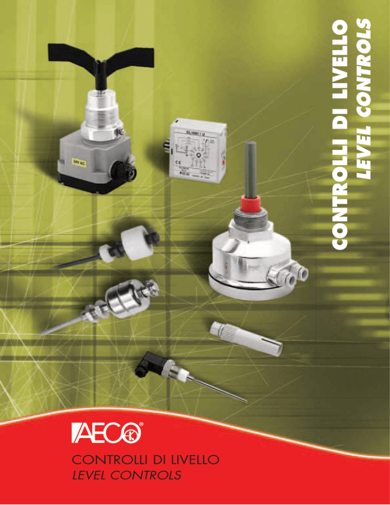
CONTROLLI DI LIVELLO
LEVEL CONTROLS
LEVEL CONTROLS
CONTROLLI DI LIVELLO
®
CONTROLLI DI LIVELLO CAPACITIVI
SERIE SC - SCD
CAPACITIVE LEVEL CONTROLS
SC - SCD SERIES
PRINCIPIO DI FUNZIONAMENTO
WORKING PRINCIPLE
Tale principio è basato sul comportamento fisico di un condensatore elettrico, la cui capacità dipende dall’area delle armature affacciate, dalla distanza fra di loro e dalla costante
dielettrica del materiale interposto.
Nel caso di controllo di livello capacitivo le armature del condensatore sono rappresentate
dalle pareti del serbatoio da un lato e dall’elettrodo di una sonda dall’altro (isolato dalle
pareti e che sporge all’interno dello stesso).
Rimanendo costanti la superficie dell’elettrodo e delle
pareti del serbatoio l’unica variabile è il materiale da
controllare che funge da dielettrico. La costante dielettrica relativa dell’aria o del vuoto è uguale a 1, mentre
quella di ogni altro materiale è per definizione superiore
a 1, quindi variando la quantità di materiale del serbatoio
si avrà una variazione di capacità del condensatore
che viene rilevata applicando agli elettrodi una tensione
alternata ad alta frequenza e all’aumentare della
capacità, conseguente al crescere del livello di riempimento, cresce anche la corrente che fluisce nel
condensatore.
Tale intensità di corrente ad alta frequenza viene
trasformata dalla centralina in una corrente continua
utilizzata per l’indicazione del livello.
The principle is based on the behavior of a capacitor the capacitance of which depends on
the area of the armatures in the vicinity, the distances between them and the dielectric constant of the material.
In the case of a capacitive level control the armatures of the capacitor are represented by
the walls of the tank on one side and by the electrode of a probe, isolated from the walls
on the other.
As the surfaces of the electrode and the walls of the
tank remain constant the only variable is the material
which acts as the dielectric. The dielectric constant
relative to air or vacuum is 1, whilst by definition that
of any other material is greater than 1, therefore by
varying the quantity of material in the tank the capacitance of the capacitor is varied and this is measured
by applying to the electrodes a high frequency alternating voltage and as the capacitance increases as a
result in the increasing level in the tank the current
flowing in the capacitor also increases.
This value of frequency current is transformed by the
control circuit into a current which is used to indicate
the level.
APPLICAZIONI
APPLICATIONS
I controlli di livello capacitivi trovano largo impiego
dove necessiti controllare con notevole sicurezza di
intervento il livello di sostanze anche non conduttrici
sia liquide che solide.
Sono particolarmente utilizzati per il controllo del
livello nei silos per cereali e foraggi, nei mangimifici,
pastifici, sementifici, biscottifici e nell’industria
alimentare in genere.
Negli impianti di trasporto, dosaggio, stoccaggio e
lavorazione di materie plastiche e prodotti petrolchimici, nelle fonderie e cementifici.
Il campo di impiego è comunque vastissimo e applicabile in ogni situazione dove si presenti
la necessità di controllare il livello in serbatoi contenenti materiali di ogni genere.
Capacitive level controls are widely used where it is
necessary to control with a good safety margin of
intervention the level of substances both liquid and
solid which may not be conductive.
They are particularly used in silos for cereals, foodstuffs, seeds, biscuit plants and the food industry in
general.
They are also used in the transport, dosing, stocking
and handling of plastic materials, petrochemical
products, in foundries and cement factories.
The field of use is vast and is practically anywhere where it is necessary to control the
level inside tanks which contain many types of different material.
REGOLAZIONE DELLA SENSIBILITÀ
SENSITIVITY ADJUSTMENT
Dopo aver installato la sonda, se il serbatoio non è conduttore, effettuare la messa a terra
tramite apposito morsetto situato nella sonda stessa. Per una corretta taratura della sensibilità è consigliabile agire sul potenziometro di regolazione, con elettrodo libero da materiale,
fino a trovare il punto di intervento del relè ed annotare la posizione del potenziometro.
Quindi immergere l’elettrodo nel materiale da controllare, agire sul potenziometro fino a
trovare il punto di intervento del relè ed annotarne la posizione. Come
ultima operazione posiMAX
zionare il potenziometro
nel punto intermedio a
quelli trovati nelle due
prove precedenti.
Sia il modello SC con
centralino incorporato
che il modello SCD con
centralino separato sono
dotati di un selettore di
sicurezza min./max livello
MIN
da posizionare opportunamente in funzione del
controllo da effettuare.
After having installed the probe, if the tank is not conductive, carry out the earthing of the
probe by connecting to the connector placed on the probe. In order to calibrate the sensitivity the adjustment potentiometer should be adjusted with the probe free from material
until the point at which the relay switches is found and this should be noted on the potentiometer. The probe should then be immersed in the material to be controlled and the potentiometer should be adjusted
once again until the relay
MAX
MIN
switches, once again note
the position. As a last operation place the position
of the potentiometer in the
mid position between the
two markings. Both the SC
model with incorporated
power supply and the SCD
model with separate power
supply are supplied with a
min/max level security
switch which can be positioned depending on the
control function that is to
be carried out.
LIMITAZIONI
Nell’utilizzo di sonde capacitive bisogna tenere presente che notevoli formazioni di depositi sulla sonda possono falsare o impedire la misura, anche se ciò è da escludersi nella maggior parte dei casi perchè gli elettrodi sono ricoperti in teflon antiaderente.
Il valore della costante dielettrica del materiale non deve essere troppo piccolo, deve
comunque differire significativamente da 1.
Inoltre bisogna tenere conto della composizione del materiale, contenuto di
umidità, temperatura ecc.
114
LIMITATIONS
When using capacitive
probes is should be borne
in mind that large deposits
adhering to the probe may affect the measurement, this can however, be discounted in
most cases as the probe is covered in teflon.
The value of the dielectric constant of the material must not be too low, it must in any case
differ significantly from 1, furthermore it is important to bear in mind the composition of the
material, humidity content, temperature etc.
®
CONTROLLI DI LIVELLO CAPACITIVI
SERIE SC - SCD
CAPACITIVE LEVEL CONTROLS
SC - SCD SERIES
MODELLI SCA - SCF
SCA - SCF TYPES
Questa versione ad esecuzione compatta presenta la parte meccanica e la parte elettronica
in una unica unità.Sono forniti con elettrodi ad asta in acciaio (SCA) rivestiti in teflon con
lunghezze standard 300-500-800 mm. oppure con elettrodi a fune (SCF) in acciaio plastificati ed elemento tenditore rivestito in teflon con lunghezze standard 1000-2000-30004000 mm. facilmente accorciabili.
This is the compact version which has both the mechanical and electronic parts in one unit.
They are supplied with bar electrodes of teflon coated steel (SCA) with standard lenghts of
300 - 500 - 800 mm, or with cable electrodes which are of plastified steel and tensioning,
weight covered in teflon (SCF) with standard lenghts of 1.000 - 2.000 - 3.000 - 4.000 mm,
these are easily shortened.
MODELLI SCDA - SCDF
SCDA - SCDF TYPES
Questa versione presenta la parte meccanica separata dalla parte elettronica che è situata
nel centralino-alimentatore-amplificatore mod. SX2. In questa versione il cavo di collegamento tra la sonda ed il centralino può essere di lunghezza illimitata, è però consigliabile
tenere separato tale cavo dai conduttori di potenza e se necessario utilizzare un cavo schermato.La parte meccanica è fornita come nella versione compatta con elettrodi ad asta e
fune con uguali caratteristiche.Questo sistema di rilevamento è utilizzato quando necessiti
avere sotto controllo sia la taratura che la visualizzazione del funzionamento in un unico
quadro di comando.
These types have the electronic and mechanical parts separate. The power supply/amplifier is situated in the SX2 unit. In this version the connection cable between the probe and
the control unit can be of any length, it is recommended that this cable be kept separate
from any power cables or that it be screened.The mechanical parts are supplied as per the
compact version with bar or cable probes of equal characteristics.This system is used when
it is necessary to have the calibration and the visualisation of operation in one control panel.
MODELLI SCD30P
SCD30P TYPES
Questa versione miniaturizzata si presenta fisicamente come un sensore capacitivo, ma
funziona in abbinamento al centralino-alimentatore-amplificatore mod. SX2. È utilizzato
principalmente quando necessita avere sotto controllo sia la taratura che la visualizzazione
del funzionamento in un unico quadro di comando, unitamente a problemi dimensionali
dove la miniaturizzazione dell’elemento sensibile risolve problemi di spazio che si presentano
in determinate applicazioni.
This minituarised version presents itself as a capacitive sensor but it works in conjunction
with the SX2 unit. It is used when it is necessary to have the calibration and the visualisation of operation in one control panel and where the small dimensions of the sensing unit
over come space problems.
REGOLAZIONE SENSIBILITÀ E SCHEMI DI COLLEGAMENTO / SENSITIVITY ADJUSTMENT AND WIRING DIAGRAMS
SCA / SCF
SCDA
SCDF
REG. SENSIBILITÀ
SENSITIVITY ADJ.
50
1
1 22 33 44
®
0
0
LED
10
-
6
+
SX2
5
4
MAX
3
RELÉ
TEST
BLU / BLUE
NERO / BLACK
BIANCO / WHITE
MARRONE / BROWN
N
3
4
5
6
7
220
0
2
110
1
MAX-MIN
6
5
MI
Nei modelli con alimentazione a 24Vca collegarsi ai morsetti 2-4
In the case of 24Vac type supply connect to terminals 2-4
6
LED
RELAY
ON
SELETTORE
SELECTOR
7
REG. SENSIBILITÀ
SENSITIVITY ADJ.
8
4
SENSIBILITY
5
4
3
9
SX2
2
10
3
SCD-30P
220
1
11
0
110
SX2
24
(AMPLIFICATORE / AMPLIFIERS)
CARATTERISTICHE MECCANICHE DELLE SONDE
MECHANICAL CHARACTERISTICS OF THE PROBES
Il corpo meccanico della sonda nella versione SC e SCD è in fusione di alluminio con due
pressacavi di uscita, attacco standard filettato da 1 1/2” GAS, fornibile anche da 1” oppure
2” GAS. Tale custodia ha un grado di protezione IP65 che ne consente l’installazione all’aperto.Nella versione SCD-30P il corpo sonda è in materiale plastico makrolon e può essere
abbinato alla custodia protettiva mod. SCM (pag. 76)
The body of the SC and SCD probes is an aluminium casting with two cable clamps on the
outputs, standard fixing 1 1/2" GAS, available also 1" ore 2" GAS. The body has a degree
of protection of IP 65 which allows for outside installation.
The body of the SCD-30P is of macrolon plastic and can be used in combination with the
SCM protection housing (Page 76)
DIMENSIONI / DIMENSIONS (mm)
CARATTERISTICHE TECNICHE / TECHNICAL CHARACTERISTICS
Tensione di alimentazione ± 15% / Supply voltage ± 15%
24Vac-110/220Vac 50÷60Hz
-20÷+60°C
Limiti di temperatura mod. SCD / SCD-30P / Temperature limits SCD / SCD-30P types
-20÷+100°C
Limiti di temperatura mod. SX2 / Temperature limits SX2 types
-20÷+60°C
SC-F
Ø120
Ø120
93
Limiti di temperatura mod. SC / Temperature limits SC types
Assorbimento / Maximum absorption
SC-A
24Vd.c.
2 x 3/8" GAS
Tensione di alimentazione a richiesta mod. SC / On request power supply SC types
2,5VA
5A a 220Vac
Grado di protezione mod. SC / SCD / IP rating SC / SCD types
IP65
Grado di protezione mod. SCD-30P / IP rating SCD-30P types
IP67
SW60
24
Uscita a relè 1 scambio / Output with 1 pole changeover
1 1/2"
GAS
300 - 500 - 800
DIMENSIONI / DIMENSIONS (mm)
SCD-30P
20
10
SX2
108
68
®
76
1000 - 2000 - 3000 - 4000
12 Kg./cmq.
Pressione max nel serbatoio / Maximum tank pressure
155
Ø17
SX2
20
Ø30
38
®
13
70
M 30 X 1,5
115
ROTATIVE LEVEL CONTROLS
RL-A (STANDARD) RL-A AD (ATEX)
CONTROLLI DI LIVELLO ROTATIVO
SERIE RL-A (STANDARD) RL-A AD (ATEX)
GENERALITÀ
GENERAL DESCRIPTION
Sono utilizzati per il controllo di livello in serbatoi contenenti
materiali in polvere o granulari. La custodia nella versione
standard è interamente in materiale plastico, invece nella
versione ATEX l’attacco filettato è in alluminio.
Il funzionamento è dovuto alla rotazione a bassa velocità di
un motorino sincrono che aziona un’elica posta all’interno
del serbatoio da controllare.
In assenza di materiale il motorino è sotto tensione e l’elica
ruota. La presenza di materiale attorno all’elica ne frena la
rotazione provocando lo scambio dei contatti di comando.
Un secondo microinterruttore disinserisce la tensione di
alimentazione del motorino.
L’elica si rimette in movimento quando il livello del prodotto
scende fino a liberarla ed il microinterruttore si riapre alimentando il motorino.
They are used for the level control in containers holding
product in powder or granule form. In the standard version
the body is made of plastic material, in the ATEX version the
threaded mounting part is made of aluminium.
The functioning is based on the slow rotation of a syncronous motor which turns the paddle which is placed in the
container.
In the absence of material the paddle turns, material coming
into contact with the paddle causes a breaking effect which
slows down the motor and in turn causes the unit to switch.
A second switch switches off the power off the motor.
The paddle starts to rotate again when the material in the
container falls freeing the paddle.
MAX
ISTRUZIONI DI MONTAGGIO
MOUNTING INSTRUCTION
L’apparecchio viene applicato sulla parete esterna del
contenitore lateralmente o dall’alto, mediante attacco filettato
1 1/2" GAS.
Il materiale deve potersi muovere liberamente attorno
all’elica che non deve essere investita dal getto diretto del
materiale. Per evitare questo inconveniente predisporre eventuali deflettori di protezione sopra il segnalatore quando il
peso sull’elica e relativo albero è elevato (materiale ad alto
peso specifico o soggetto a movimenti in blocco).
The unit is placed on the external wall of the container
mounted it by means of a standard fixing 1 1/2" GAS.
The material must be able to move freely around the paddle
and this must not be installed in the jet of material.
In order to avoid this it may be necessary to install deflectors above the unit when the mass of the material is high.
MIN.
SCHEMI DI COLLEGAMENTO/WIRING DIAGRAMS
TENSIONE DI ALIMENTAZIONE C.C.
SUPPLY VOLTAGE D.C.
M3
1
M2
1
TENSIONE DI ALIMENTAZIONE C.A.
SUPPLY VOLTAGE A.C.
1
2 PE
M1
1
2 PE
L
N
CONTATTO DI USCITA / OUTPUT CONTACT
A B C
RL-A STANDARD
RL-A AD ATEX
8
REG. SENSIBILITÀ
SENSIBILITY ADJ.
8
7
6
7
6
5
5
MOLLA DI REG.
REG. SPRING
La molla di regolazione della forza di rotazione è regolabile
in tre posizioni: / The power rotation regulation spring can
be adjusted as follows:
A = debole / weak
B = media / average
C = dura / hard
2A / 250V
M1
M2
250V
300V
blu/blue
24Vac (*)
rosso/red
marrone/brown
blu/blue
48Vac
rosso/red
blu/blue
marrone/brown
110Vac (*)
rosso/red
marrone/brown
blu/blue
220Vac
rosso/red
blu/blue
marrone/brown
* Collegamenti pre impostati / Pre-set connection
A: Fissare la vite dopo avere effettuatro la
procedura B.
Fix the screw after procedure B
A
M3
marrone/brown
116
2A
2A
Pmax
600Va
(coso=1)
60W
CONSIGLI PER IL MONTAGGIO / SUGGESTIONS FOR MOUNTING
rosso/red
24Vdc
Vmax
N.B.: il contatto è rappresentato con apparecchiatura sotto tensione ed elica in movimento.
N.B.: The contact is on when the device is under tension and the paddle is moving.
Modalità di cambio tensione per modelli non ATEX
Instructions for change supply voltage for non ATEX models
ALIMENTAZIONE
SUPPLY VOLTAGE
AC
DC
Imax
B: Montaggio corretto. Il pressacavo deve
essere rivolto verso il basso.
For a correct mounting the cable gland
must be facing downwards.
C
B
C: Per facilitare l’entrata dell’elica nel foro
di fissaggio tagliare un’aletta.
To facilitate entrance of paddle in the
fixing hole pls. cut a paddle.
®
ROTATIVE LEVEL CONTROLS
RL-A (STANDARD) RL-A AD (ATEX)
CONTROLLI DI LIVELLO ROTATIVO
SERIE RL-A (STANDARD) RL-A AD (ATEX)
CARATTERISTICHE TECNICHE RL-A STANDARD / TECHNICAL CHARACTERISTICS RL-A STANDARD
MODELLO/MODE
RL-A 24Vdc
Custodia / Housing
Temperatura / Temperature
Pressione / Pressure
Sensibilità / Sensibility
Tensione di alimentazione / Supply voltage
Assorbimento max. / Max absorption
Attacco filettato / Standard fixing
Grado di protezione / IP rating
24 Vdc
RL-A 24/48Vac
Plastica grigia PA6 / Grey plastic PA6
-20 ÷+80°C
0,5 ÷ 1,8 bar
100g/l-regolabile in 3 posizioni / 3 positions adjustable
24/48 Vac
3W / 3,5VA
1 1/2 inch Gas - PA6 GF30 Plastica nera / Black plastic
IP 66
RL-A 110/220Vac
110/220 Vac
CARATTERISTICHE TECNICHE RL-A AD ATEX / TECHNICAL CHARACTERISTICS RL-A AD ATEX
MODELLO/MODE
RL-A AD1/3 24Vdc
Custodia / Housing
Temperatura / Temperature
Pressione / Pressure
Sensibilità / Sensibility
Tensione di alimentazione / Supply voltage
Assorbimento max. / Max absorption
Attacco filettato / Standard fixing
Grado di protezione / IP rating
Marcatura / Marking
RL-A AD1/3 24Vac
RL-A AD1/3 48Vac RL-A AD 1/3 110Vac RL-A AD1/3 220Vac
Plastica PA6 grigia e attacco filettato in alluminio / Grey plastic PA6 and standard fixing in aluminium
-20 ÷+80°C
0,8 ÷ 1,1 bar
100g/l-regolabile in 3 posizioni / 3 positions adjustable
24 Vdc
24 Vac
48 Vac
110 Vac
220 Vac
3W / 3,5VA
1 1/2 inch Gas - Alluminio / Aluminium
IP 66
II 1/3D IP 66 T95°C
DIMENSIONI (mm) E ACCESSORI / DIMENSIONS (mm) AND ACCESSORIES
ESTENSIONI/EXTENSIONS
RL-A STANDARD
FUNE/ROPE
ASTA/BAR
M20x1,5
80x88
MOLLA / SPRING
66
A
B
L max 2m
L max 1m
212
L=300
L=400
L=500
L=600
150
N.B. IL CONTROLLO DI LIVELLO VIENE FORNITO NELLA VERSIONE BASE COME DA FIGURA A SINISTRA
(RL-A STANDARD). L’ESTENSIONE O PROLUNGA PUÒ ESSERE AD ASTA CON LUNGHEZZE STANDARD DA
500 E 1000 mm ACCORCIABILI OPPURE A FUNE CON LUNGHEZZA DI 2000 mm ACCORCIABILE.
LE ESTENSIONI VANNO ORDINATE SEPARATAMENTE DALLA VERSIONE BASE DEL CONTROLLO DI LIVELLO
E NON SONO COMPRENSIVE DI ELICA.
N.B. THIS LEVEL CONTROL IS SUPPLIED IN THE STANDARD VERSION AS PER DRAWING ON THE LEFT
(RL-A STANDARD). THE AVAILABLE STANDARD LENGTHS ARE 500 AND 1000 mm WHICH CAN BE
SHORTENED, THESE ARE ALSO AVAILABLE IN THE 2000 mm CABLE VERSION WHICH CAN BE
SHORTENED AS WELL. THE EXTENSIONS MUST BE ORDERED SEPARATELY FROM THE STANDARD VERSION
AND THE PADDLE IS NOT INCLUDED.
®
B
L=700
L=800
A
L=900
A
L=1000
A = SPINA DI FISSAGGIO / COTTER PIN
B = VITE STRINGICAVO / CABLE TIGHTINING SCREW
117
N.B.: la forza necessaria per bloccare la rotazione dell'albero corrisponde a circa
1 kg con elica standard
N.B.: the force to be applied for stopping the shaft rotation corresponds to 1 kilo
with standard paddle.
CONTROLLO DI LIVELLO A MEMBRANA
PER SOLIDI SM-85
MEMBRANE LEVEL CONTROL
FOR SOLIDS SM-85 MODEL
GENERALITÀ
GENERAL DESCRIPTION
Questa apparecchiatura è adatta al controllo del livello minimo e massimo in silos o
tramoggie contenenti materiali non collosi, in polvere o granuli, quali riso, cereali, materie
plastiche, caffé, sabbia, ecc. Il funzionamento è dovuto alla
pressione esercitata dal prodotto sulla membrana in gomma che
aziona un microinterruttore a scatto rapido.
La sensibilità dello scatto è regolabile tramite una vite situata sul
coperchio dell’apparecchiatura, tale sensibilità va regolata in funzione del materiale da controllare e della pressione che lo stesso
esercita sulla membrana in funzione del suo peso specifico.
Variazioni di umidità e temperatura non compromettono il buon
funzionamento, inoltre la membrana è resistente ad urti e vibrazioni.
This unit is suitable for controlling the maximum and minimum levels. In silos and tanks
containing materials such as powder, granule, such as rice, cereals, plastic material,
coffee, sand, etc.
Its functioning is due to the pressure created by a product on the
rubber membrane which activates a fast acting microswitch.
The sensitivity of the switching can be adjusted by means of a
screw placed on the lid of the unit, adjustment is made depending
on the material to be sensed as a function of its specific weight.
Variations in humidity and temperature do not compromise the
functioning, furthermore the membrane is resistant to blows and
vibrations.
ISTRUZIONI DI MONTAGGIO
MOUNTING INSTRUCTION
L’installazione di questo tipo di controllo deve essere effettuata
esternamente sulla parete laterale del silos o della tramoggia
mediante i tre fori posti sulla flangia di fissaggio praticando un
foro nel contenitore del diametro di 86 mm per permettere al
materiale da controllare di entrarne in contatto.
The unit must be assembled on the external wall of silos or tanks
by means of the three holes situated on the fixing flanges and by
making a hole of 86 mm diameter in the container so as to allow
contact with the material.
SCHEMA
ELETTRICO
ELECTRICAL
DIAGRAM
DIMENSIONI / DIMENSIONS (mm)
70
Ø115
Interasse Ø100 (tre fori a 120°)
Ø100 (3 holes at 120°)
2
23
45
Ø6,5
CARATTERISTICHE TECNICHE / TECHNICAL CHARACTERISTICS
Contenitore plastico / Plastic housing
Flangia di fissaggio / Fixing flange
Ø85
Ø87
Membrana / Membrane
1/NC
Contatti elettrici / Electrical contacts
ABS autoestinguente / Autoextinguishing ABS
Alluminio / Aluminium
Neoprene diam. 82 mm. / Neoprene 82 mm. dia.
6A a 250V / 6A at 250V
2/NO
3/C
Membrana in gomma
Rubber membrane
Vite di reg. sensibilità
Screw for sensitivity adj.
118
Pressacavo 1/4”
Cable guand 1/4"
Flangia di fissaggio
Fixing flange
Limiti di temperatura / Temperature limits
Grado di protezione / IP rating
Sensibilità di risposta / Response sensitivity
-10 ÷ +60 °C
IP 55
Min. 50 gr. centrali, 20 mm. di pressione d'acqua sulla membrana
Min. 50 gr central, 20 mm. water pressure on membrane
®
MAGNETIC LEVEL CONTROLS
SLM-SLM/P SERIES
CONTROLLI DI LIVELLO MAGNETICI
SERIE SLM-SLM/P
GENERALITÀ
GENERAL DESCRIPTION
I controlli di livello magnetici per liquidi sono costituiti
da un contatto reed situato all’interno dell’asta e da un
magnete di azionamento alloggiato nel galleggiante
che scorre sulla stessa per effetto dell’aumento o
della diminuzione del livello da controllare. Il principio
di funzionamento è identico a quello dei sensori
magnetici (vedere pag. 100-101).
Sono disponibili in tre modelli: uno in custodia plastica
e due in acciaio inox aisi 316 per temperature rispettivamente di +100°C e +150°C.
Magnetic level controls for liquids are made of a reed
contact placed inside the shaft and an operating
magnet placed in the float which runs due to the
increase or decrease of the level to detect.
The working principle the same as our magnetic
sensors (pls. see page 100-101).
There are 3 models available: one made of plastic
housing and two made of AISI 316 stainless steel
suitable for high temperatures of +100°C e +150°C.
CARATTERISTICHE TECNICHE / TECHNICAL CHARACTERISTICS
MODELLO/MODE
Peso specifico min. del liquido / Min liquid specific gravity
Distanza di intervento / Switching distance
Tensione di commutazione max. / Max switching voltage
Corrente di commutazione max. / Max switching current
Potenza di commutazione max. / Max switching power
Frequenza di lavoro max. / Max switching frequency
Tempo di attuazione contatto / Contact actuation time
Ripetibilità / Repeatability
Limiti di temperatura / Temperature limits
Grado di protezione / Ip rating
Cavo / Cable
Corpo custodia / Body Housing
Custodia galleggiante / Float Housing
Kg/dm3
mm
V
A
W/VA
Hz
ms
mm
°C
IP
0,5m
SLM/P-08 NO
SLM-08 NO GM1
SLM-08 NO GM1 150°C
SLM000001
SLM000002
SLM000004
0,9
>3
125
1
10
230
2
±0,3
-20 ÷ +100
67
PVC 2x0,25
Polypropylene
Polypropylene
0,75
>3
250
0,5
50
230
2
±0,3
-20 ÷ +100
67
PVC 2x0,25
AISI 316
AISI 316
0,75
>3
200
1
20
230
2
±0,3
-20 ÷ +150
67
Teflon 2x0,25
AISI 316
AISI 316
DIAGRAMMI COMMUTAZIONE DI POTENZA / SWITCHING POWER DIAGRAMS
SLM/P-08 NO
SLM-08 NO GM1
SLM-08 NO GM1 150°C
V
V
V
125
250
250
100
200
200
75
150
150
50
100
100
25
50
50
0
0
0,2
0,4
0,6
0,8
1,0
I
SCHEMA DI COLLEGAMENTO / WIRING DIAGRAM
0
0
0,2
0,4
0,6
0,8
0
1
0
0,2
DIMENSIONI / DIMENSIONS (mm)
0,4
0,6
0,8
1
SLM-08 NO GM1
SLM-08 NO GM1 150°C
MARRONE / BROWN
500
SLM/P-08 NO
500
BLU / BLUE
1/8” GAS
CH14
M8x1.25
19
N.B.: This level control is supplied with NO output contact,
but can obtain the NC function simply by turning
the float up-side-down.
14
N.B.: Il controllo di livello viene fornito con contatto di
uscita normalmente aperto N.O.
Si può ottenere la funzione inversa N.C.
capovolgendo il galleggiante.
28
Ch. 13
Hex 13
64
NO
30
MARRONE / BROWN
BLU / BLUE
Seeger
NC
ø 25
®
50
16
28
GALLEGGIANTE
FLOAT
Sn
Seeger
Ø8
119
CONTROLLI DI LIVELLO A CONDUCIBILITÀ
SERIE CL1001-CL1002
CONDUCTIVITY LEVEL CONTROLS
CL1001-CL1002 SERIES
PRINCIPIO DI FUNZIONAMENTO
WORKING PRINCIPLE
I controlli di livello CL1001-CL1002
funzionano sulla conducibilità dei liquidi
e rilevano il livello tramite degli elettrodi
posti nel liquido stesso. La presenza di
liquido tra l’elettrodo (o gli elettrodi) e la
superficie metallica del serbatoio (o elettrodo di massa) provoca il funzionamento del circuito elettronico posto nell’unità
di controllo e la conseguente commutazione del relè di uscita. Si può effettuare
anche il rilevamento di solidi purchè la
conducibilità del materiale sia compresa
nel campo di funzionamento dell’unità
che nell’esecuzione standard arriva
fino a 40 Kohm. Altri modelli in grado di
rilevare materiale con resistività fino a
1 Mohm sono disponibili a richiesta.
La bassa tensione e corrente alternata
applicata agli elettrodi ed il perfetto
isolamento fra questi ultimi e la linea
garantiscono un funzionamento sicuro e
non pericoloso. Sono utilizzati come controlli di livello in serbatoi, caldaie, pozzi profondi ed altri contenitori e come dispositivi di
allarme per il rilevamento di straripamenti, presenza o assenza d’acqua in qualsiasi luogo
o controllo dell’accumulo del ghiaccio.
L’apparecchiatura viene fornita in versione monotensione con attacco octal, intercambiabile
con la maggior parte delle marche presenti sul mercato ed in versione multitensione con
attacco undecal.
The CL 1001 - CL 1002 level controls
work on the resistivity of liquids and
sense the level via the electrodes placed
in the conductive liquids.
The presence of liquid between the
electrode (or electrodes) and the metal
surface of the container (or earth electrode) causes the functioning of the
electronic circuit in the control unit and
the subsequent commutation of the
output relay.
It is also possible to sense solids as long
as the conductivity of the material is
within the range of the unit which in its
standard form reaches 40 KOhm.
Other models which can sense materials
with a resistivity up to 1 MOhm are
available on request. The low alternating
voltage and current applied to the electrodes and the isolation level between
them guarantees a safe operation.
They are used as level controls in tanks,
heaters deep wells and other containers and as alarm units for overfilling and the checking
of ice accumulation.
The unit is supplied in single voltage form with an octal base and is interchangable with
most of the units available on the market. It can also be supplied in a multivoltage version
with undecal base.
MODELLI DISPONIBILI
TYPE AVAILABLE
Mod. CL1001/O: Controllo di livello monotensione con alimentazione a 24Vca oppure
110Vca oppure 220Vca ad innesto octal, questo modello è intercambiabile con la maggior
parte delle marche presenti sul mercato. Trattasi della versione più economica della serie.
Type CL1001/O: Single voltage level control with power supply at 24Vac, or 110Vac, or
220Vac supplied with octal base. It is the most economic type of this series.
Mod. CL1001/U: Controllo di livello multitensione, può essere alimentato a 110Vca oppure
a 220Vca cambiando il tipo di collegamento. Questa versione è ad innesto undecal e può
essere fornita anche a 24Vca monotensione.
Type CL1001/U: Multi voltage level control either at 110Vac, or 220Vac, by changing the
wiring diagram. It is supplied with undecal base it is also available at 24Vac single voltage.
Mod. CL1002/U: Controllo di livello monotensione con alimentazione a 24Vca oppure
110Vca oppure 220Vca ad innesto undecal. Questa versione è provvista di un relè di uscita
con doppio scambio 5A a 220Vca.
Type CL1002/U: Single voltage level control available with power supply at 24Vac or
110Vac or 220Vac, it is supplied with undecal base and relay output with 2 pole changeover
5A at 220Vac.
RITARDO ANTIONDA R5: A richiesta è possibile ritardare di 5 sec. (non regolabili) l’intervento del controllo CL1001 in modo che tumultuosità del liquido non provochino commutazioni indesiderate.
R5 ANTI-WAVE DELAY: On request it is possible to delay for 5 sec. (non-adjustment) so the
wave created by the liquid does not cause commutation.
GAMME DI SENSIBILITÀ: Premesso che i modelli suddetti sono tutti provvisti di regolazione
della sensibilità, sono disponibili diversi campi di funzionamento come da tabella.
RANGE OF SENSITIVITY: All type are supplied with sensitivity adjustment and are also
available with special sensitivity, see table below.
CAMPI DI FUNZIONAMENTO / SPECIAL SENSITIVITY RANGE
SIGLA PER ORDINAZIONE / REFERENCE FOR ORDERING
200 ohm ÷ 10 Kohm
10 K
40 K (standard)
2 Kohm ÷ 40 Kohm
10 Kohm ÷ 200 Kohm
10 Kohm ÷ 500 Kohm
200 k
500 k
1000 K
10 Kohm ÷ 1000 Kohm
CARATTERISTICHE TECNICHE / TECHNICAL CHARACTERISTICS
Tensione di alimentazione Mod. CL1001/0 / Supply voltage type CL1001/0
Tensione di alimentazione Mod. CL1001/U / Supply voltage type CL1001/U
Tensione di alimentazione Mod. CL1002/U / Supply voltage type CL1002/U
Tensione tra gli elettrodi / Voltage between the electrodes
Assorbimento / Absorption
Uscita a relè 1 scambio (Mod. CL1001) / Relay output with 1 pole changeover
Uscita a relè 2 scambio (Mod. CL1002) / Relay output with 2 pole changeover
Limiti di temperatura / Temperature limits
Grado di protezione / IP rating
Sensibilità regolabile standard / Sensitivity adjustment
LED visualizzatore / LED
120
24-110-220V ± 15% 50-60Hz
24-110/220V ± 15% 50-60Hz
24-110-220V ± 15% 50-60Hz
12Vac
3.5VA
5 A a 220 Vac
5 A a 220 Vac
- 20 + 60°C
IP40
2÷40 KOhm (On request higher)
funzione relè ON-OFF / relay ON-OFF
®
CONDUCTIVITY LEVEL CONTROLS
CL1001-CL1002 SERIES
CONTROLLI DI LIVELLO A CONDUCIBILITÀ
SERIE CL1001-CL1002
SCHEMI DI COLLEGAMENTO / WIRING DIAGRAMS
CL1001/O
CL1001/U
CL1002/U
ALIMENTAZIONE / POWER SUPPLY
ALIMENTAZIONE / POWER SUPPLY
ALIMENTAZIONE / POWER SUPPLY
24V-110V-220V
24V-110V / 220V
24V-110V-220V
110 0
24
COM.
N.O.
5A
220V
N.C.
5
4
5A
220V
6
10
N.C.
3
7
2
1
COM.
8
N.O.
220
11 1
2
10
5A
220V
3
9
4
8
7
2
3
9
4
8
7
5
6
11 1
6
5
MAX.
COM.
MIN.
MAX.
MIN.
COM.
COM.
MIN.
MAX.
CONTROLLO DI UN LIVELLO
ONE LEVEL CONTROL
Utilizzare una sonda di riferimento o la massa del serbatoio ed una sonda di livello da
collegare al morsetto corrispondente al massimo livello. Quando il liquido lascia la sonda
di livello il relè fornisce il consenso al riempimento del serbatoio. (Usare il contatto N.C. del
relè di uscita).
Use a reference probe or the tank earthing and a level probe. (To be connected to the
terminal that corresponds to the max. level).
When the liquid leaves tha probe level max. the relay switches in order to permit the tank
to be filled. (Use output contact N.C. of relay).
CONTROLLO A DUE LIVELLI (Caricamento)
TWO LEVEL CONTROL (Filling)
Utilizzare una sonda di riferimento o la massa del serbatoio, una sonda di minimo livello ed
una sonda di massimo livello. Il caricamento del serbatoio inizia quando il liquido lascia la
sonda di minimo e si arresta quando raggiunge la sonda di massimo. (Usare il contatto N.C.
del relè di uscita).
Use a reference probe or the tank earthing, min. level probe and max. level probe.
Tank filling begins the liquid leaves the minimum probe and switches off when the max.
probe is reached. (Use output contact N.C. of relay).
CONTROLLO A DUE LIVELLI (Svuotamento)
TWO LEVEL CONTROL (To empty)
Utilizzare una sonda di riferimento o la massa del serbatoio, una sonda di minimo livello ed
una sonda di massimo livello. Lo svuotamento inizia quando il liquido tocca la sonda di
massimo e si arresta quando il liquido abbandona la sonda di minimo. (Usare il contatto
N.O. del relè di uscita).
Use a reference probe or the tank earthing, min. level probe and max. level probe. The
empting begins when the liquid reaches the max. probe and switches off when the liquid
abbandons the min. probe. (Use output contact N.O. of relay).
SIGLA DI IDENTIFICAZIONE / IDENTIFICATION REFERENCE
INNESTO / PLUG
SENSIBILITÀ* / SENSITIVITY*
TENSIONE DI ALIMENTAZIONE
POWER SUPPLY
CL
1001
CONTROLLO DI LIVELLO
-
U R5 10K 24
MODELLO
TYPE
LEVEL CONTROL
RITARDO ANTIONDA**
ANTI-WAVE DELAY**
* Specificare solo se diversa da standard. / Specify only if different from the standard
** Specificare solo se richiesto. / Specify only if requested.
10
DIMENSIONI / DIMENSIONS (mm)
®
CONDUCTIVITY
LEVEL CONTROL
76
RELAY
ON
SENSIBILITY
38
®
13
70
121
PORTAELETTRODI PER CONTROLLI
DI LIVELLO A CONDUCIBILITÀ
ELECTRODE HOLDER FOR
CONDUCTIVITY LEVEL CONTROLS
GENERALITÀ
GENERAL CHARACTERISTICS
Sono sonde provviste di elettrodi, idonei al rilevamento di liquidi conduttivi, da abbinare ai
controlli di livello CL1001 e CL1002.
Sono costituite da un portaelettrodo in acciaio o in materiale plastico e da un elettrodo
separato che può essere fornito in diverse lunghezze in funzione delle esigenze.
These units are supplied with electrodes which are suitable for the sensing of conductive
liquids, to be used with level controls CL1001 and CL1002.
They consist of a stainless steel electrode support or plastic material and a separate electrode which can be supplied with different length according to the different requirements.
SONDA UNIPOLARE MOD. CL/1N
ONE POLE DETECTOR TYPE CL/1N
È una sonda unipolare che trova impiego nel controllo di livello in pozzi o in serbatoi di
accumulo. Consta di un elettrodo in acciaio inossidabile AISI 316, di un portaelettrodo in
policarbonato e di un pressacavo; un anello di tenuta posto nel lato inferiore e la chiusura
del pressacavo impediscono l’ingresso dell’acqua al morsetto di attacco del cavo e la
conseguente ossidazione. Temperatura massima d’impiego +80°C.
This one pole detector is used for level controls of wells or tanks.
It consists of a stainless steel electrode AISI 316, a polycarbonate electrode holder and a
cable gland. The sealing ring placed on the lower part and gland prevents the liquid from
entering into contact with the cable connection causing subsequent oxidization.
Max. working temperature: +80°C.
SONDA UNIPOLARE MOD. CL-A
ONE POLE DETECTOR TYPE CL-A
È una sonda unipolare che trova applicazione nel controllo di livello su caldaie, autoclavi ed
in genere dove vi siano condizioni di pressione (max 12 kg cmq) e alta temperatura
(max 200°C). Consta di un supporto in acciaio inox AISI 316 con cappuccio di protezione in
gomma, isolante in teflon e portaelettrodo in acciaio AISI 316.
This one pole detector is used for level controls in boilers, autoclaves in all conditions where
there are pressure (12 kg/cmq) and high temperatures (max. 200°C).
It consists of a stainless steel holder AISI 316 with a rubber cap of protection, insulating
material of teflon and stainless steel electrode support AISI 316.
SONDA BIPOLARE MOD. CLK-A
TWO POLE DETECTOR TYPE CLK-A
Il portaelettrodo è provvisto di un connettore a tre poli per il collegamento elettrico, due dei
quali collegati all’elettrodo ed il terzo di massa collegato internamente al supporto filettato
in acciaio. Con questo sistema se il serbatoio è in materiale metallico si evita l’installazione
della sonda di massa ed i collegamenti elettrici risultano semplificati. Consta di un supporto
in acciaio inox AISI 316 provvisto di connettore, isolante in teflon e portaelettrodo in acciaio
AISI 316.
Pressione max di esercizio 12 kg cmq e temperatura max 100°C limitata dalla presenza del
connettore in materiale plastico che garantisce una protezione IP65.
The electrode holder is provided with a three pole connector for the electrical connection,
two poles are connected to the electrode and the third, earth pole, is connected to the
thread stainless steel holder. Using this method if the tank is in metallic material it is not
necessary to install a earthing probe simplifing the wiring diagrams. It consists of a stainless steel holder AISI 316, provided with connector, supported by a teflon coated element
and electrode holder AISI 316.
Max. working pressure: 12 kgs cmq and max. temperature at 100°C limited by the
presence of the connector in plastic material which guarantees an IP65 rating with output
cable of dia. ≥6mm.
SONDA TRIPOLARE MOD. CL3-A
THREE POLE DETECTOR TYPE CL3-A
Il portaelettrodi è in materiale plastico termoindurente con tre supporti in ottone con attacco
M6 per elettrodi diam. 6mm, questi esclusi dalla fornitura, e completo di calotta coprimorsetti (in dotazione, adattatori per elettrodi standard Ø 4 mm).
Adatto per temperatura fino a 130°C e per applicazioni non in pressione.
A richiesta è fornibile una staffa in metallo per il fissaggio del portaelettrodo (mod. FCL3).
The electrode holder is thermosetting plastic material with terminal block cover and three
nickelled brass holders with M6 plug for electrode 6 mm dia. (these are not included).
It is supplied with adapter to be used with standard electrode 4 mm dia. It is suitable for
temperature up to 130°C and non-pressure application.
On request a metallic bracket is available for flange fixing to electrode holder (type FCL3).
ELETTRODI
ELECTRODES
Sono forniti in cinque diverse lunghezze 100, 300, 500, 700, 1000 mm, diam. 4mm in
acciaio inox AISI 316. Possono essere abbinati alle sonde mod. CL-A, CLK-A e CL3-A
tramite adattatori. Per l’ordinazione del modello della lunghezza desiderata specificare la
sigla relativa: E-100, E-300, E-500, E-700, E-1000.
They are supplied with five different lenght: 100, 300, 500, 700, 1000 mm, 4 mm dia.,
stainless steel AISI 316. They can be used together with CL-A, CLK-A and CL3-A with
special adapter. When ordering add "E" to the length required: E-100, E-300, E-500, E-700,
E-1000.
DIMENSIONI / DIMENSIONS (mm)
CL/1N
FCL-3
72
27
25
M6
Ø 96
78
Ø 62
11
300 - 500 - 700 - 1000
Ø4
2
18
9
M4
6
2" Gas
30
3/8" Gas
11
300 - 500 - 700 - 1000
Ø4
30
3/8" Gas
96
M4
41
Connett. K
9
Rubber
cap
CH 22
CH 22
35
PG7
20
10
mPm
73
25
7
30
Ø8
CL3-A
CLK-A
CL-A
Ø21
Ø 115
90
122
®

