N520 GD
M120
Sensore / Sensor
Magnete / Magnet
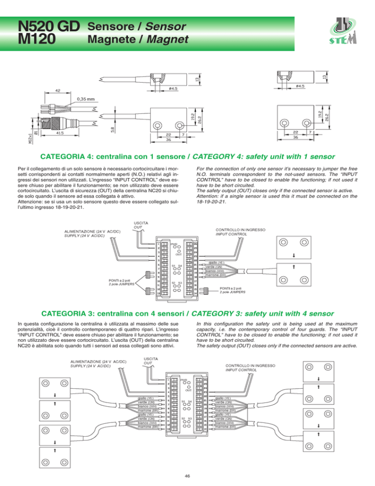
CATEGORIA 4: centralina con 1 sensore / CATEGORY 4: safety unit with 1 sensor
Per il collegamento di un solo sensore è necessario cortocircuitare i morsetti corrispondenti ai contatti normalmente aperti (N.O.) relativi agli ingressi dei sensori non utilizzati. L’ingresso “INPUT CONTROL” deve essere chiuso per abilitare il funzionamento; se non utilizzato deve essere
cortocircuitato. L’uscita di sicurezza (OUT) della centralina NC20 si chiude solo quando il sensore ad essa collegata è attivo.
Attenzione: se si usa un solo sensore questo deve essere collegato sull’ultimo ingresso 18-19-20-21.
For the connection of only one sensor it’s necessary to jumper the free
N.O. terminals correspondent to the not-used sensors. The “INPUT
CONTROL” have to be closed to enable the functioning; if not used it
have to be short circuited.
The safety output (OUT) closes only if the connected sensor is active.
Attention: if a single sensor is used this it must be connected on the
18-19-20-21.
CATEGORIA 3: centralina con 4 sensori / CATEGORY 3: safety unit with 4 sensor
In questa configurazione la centralina è utilizzata al massimo delle sue
potenzialità, cioè il controllo contemporaneo di quattro ripari. L’ingresso
“INPUT CONTROL” deve essere chiuso per abilitare il funzionamento; se
non utilizzato deve essere cortocircuitato. L’uscita (OUT) della centralina
NC20 è abilitata solo quando tutti i sensori ad essa collegati sono attivi.
In this configuration the safety unit is being used at the maximum
capacity, i.e. the contemporary control of four guards. The “INPUT
CONTROL” have to be closed to enable the functioning; if not used it
have to be short circuited.
The safety output (OUT) closes only if the connected sensors are active.
46
Sensore / Sensor
Magnete / Magnet
CONTATTO E CARATTERISTICHE ELETTRICHE
CONTACT AND ELECTRICAL CHARACTERISTICS
CORPO
BODY
Serie
Series
Tipo
Type
N520
GD
Schema elettrico
Electrical scheme
CAVO
CABLE
GD
QN
SERIES
TIPO CONTATTO
0
CABLE TYPE
CENTRALINA
CONTROL UNIT
Corrente
Current
A
Tipo
Type
Diametro
Diameter
mm
Conduttori
Conductors
mm
Caratteristiche
Characteristics
Attivazione
Activation
mm
Disattivazione
Deactivation
mm
Reset
Reset
mm
Serie
Series
Tipo
Type
24
10
0,5 max
QN
6
AWG 22
Quadripolare nero
Black Quadripolar
<3
>9
> 12
M120
NC20
200
Rectangular shaped contactless safety sensors with holes for fixing
screws to be used in combination with NC20 safety module.
The N520 GD sensors guarantees category 4 of EN 954-1; they could be
activated only using the apposite coded magnet type M120 so they are
guaranteed against undesired activations or manipulations. On the
active side there’s a referring painting for the correct alignment between
sensor and magnet.
The sensors combined with NC20 safety unit, in addition to the activation
and deactivation distances, have also a reset value that is the distance
at which the sensor have to be moved back from the magnet in order to
have a new reactivation.
The sensors are available with different cable’s length (200, 300, 400,
500 cm) or with connector on a 20 cm cable.
The coded magnet types M120 has two fixing holes to be used with
stainless steel screws and nuts.
Codice sensore con connettore
Order code Sensor with connector
Connettore
Connector
Lunghezza cavo
Cable length
M 12 x 1
cm. 20
CONTACT TYPE
TIPO CAVO
MAGNETE
MAGNET
Potenza
Power
W
Esempio di sigla di ordinazione
Order code example
N520
DISTANZE
DISTANCES
Tensione
Voltage
V
Sensori di sicurezza senza contatto di forma rettangolare con fori per viti di fissaggio da utilizzare in abbinamento con la centralina NC20.
I sensori N520 GD garantiscono una categoria di sicurezza 4 secondo
EN 954-1; essi possono essere attivati solo mediante l’apposita unità
magnetica codificata M120 e sono quindi garantiti da attivazioni indesiderate o da manipolazioni. Sul lato attivo sono presenti dei riferimenti serigrafici per l’attivazione del sensore.
I sensori abbinati alla centralina NC20, oltre ad avere una distanza di attivazione e disattivazione, presentano anche un valore di reset che rappresenta la distanza a cui deve essere portato il sensore rispetto all’unità magnetica per poter avere una nuova riattivazione.
Sono fornibili con cavo di varia lunghezza (200, 300, 400, 500 cm) o con
connettore montato su un cavo di 20 cm.
L’unità magnetica M120 è provvista di fori per il fissaggio attraverso viti e
dadi in acciaio inox.
SERIE
N520 GD
M120
Dati tecnici
Technical Data
Materiale del corpo
Housing Material
Temperatura di lavoro
Working temperature
Grado di protezione
Degree of protection
N520GDQN0M12
CARATTERISTICHE SPECIALI
SPECIAL FEATURES
LUNGHEZZA IN cm (STANDARD 200 cm).
Lunghezze disponibili: 200, 300, 400, 500 cm.
LENGTH IN cm (STANDARD 200 cm).
Available lengths: 200, 300, 400, 500 cm.
47
Sensors
N520 GD
Magnets
M120
SPS caricato vetro
glass-fiber reinforced SPS
-30 ... +100°C
-30 ... +120°C
IP 67 (IEC 60529)
Resistenza alle vibrazioni
Vibration resistance
in accordo con / in accordance with
EN 60947-5-2
Resistenza agli shock
Shock resistance
in accordo con / in accordance with
EN 60947-5-2
Compatibilità elettromagnetica
EMC compliance
in accordo con / in accordance with
EN 61496-1 / EN 50022 part A

