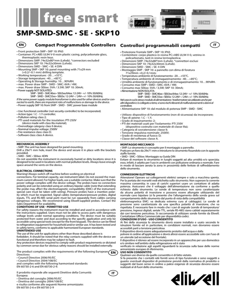
SMP-SMD-SMC ∙ SE ∙ SKP10
EN
Compact Programmable Controllers Controllori programmabili compatti
• Front protection SMP • SKP 10: IP65
• Container: PC+ABS UL94 V-0 resin plastic casing, polycarbonate glass, thermoplastic resin keys.
• Dimensions SMP: 74x32x80*mm (Lxhxb). *connectors excluded
• Dimensions SKP 10: 74x32x30mm (Lxhxb).
• Dimensions SMD - SMC • SE: 4 DIN
• Mounting SMP • SKP 10: panel mounting with 71x29 mm
(+0.2/–0.1 mm) drilling template.
• Working temperature: -20…+55°C.
• Storage temperature: -40…+85°C;
• Operating & Storage humidity: 10…90%RH.
• max. Power draw SMP - SMD - SMC: 6VA / 4W;
• max. Power draw SE6xx: 5VA / 3.5W; SKP 10: 30mA;
• Power supply NOT ISOLATED:
SMP - SMD - SMC46xx • SE63xx/64xx: 12-24Va +/- 10% 50/60Hz;
SMP - SMD - SMC55xx • SE65x: 12-24Va / 24Vc +/- 10% 50/60Hz;
If the same power supply module/transformer is also used for other devices and/or connected to earth, there are important risks of malfunctions or damage to the device.
• Power supply SKP 10: from SMP - SMD - SMC power base module
• Use: functional controller (not security controller) to be incorporated;
• Action type: 1.C - 1.Y controller;
• Pollution rating: class 2;
• PTI used materials for the insulation: PTI 250V
(device made with class IIIa material);
• Overvoltage category: class II device;
• Nominal impulse voltage: 2500V
• Fire resistance class: class D;
• Software class: class A device.
• Protezione frontale SMP • SKP 10: IP65
• Contenitore: corpo plastico in resina PC+ABS UL94 V-0, vetrino in
policarbonato, tasti in resina termoplastica;
• Dimensioni SMP: 74x32x80*mm (Lxhxb). *connettori esclusi
• Dimensioni SKP 10: 74x32x30mm (Lxhxb).
• Dimensioni SMD - SMC • SE: 4 DIN
• Montaggio SMP - SKP 10: a pannello con dima di foratura
71x29mm +0,2/-0,1mm;
• Temperatura ambiente di funzionamento: -20…+55°C.
• Temperatura ambiente di immagazzinamento: -40…+85°C;
• Umidità ambiente di funzionamento e di immagazzinamento: 10…90%RH.
• Consumo max SMP • SMD • SMC: 6VA / 4W;
• Consumo max SE6xx: 5VA / 3,5W; SKP 10: 30mA;
• Alimentazione NON ISOLATA:
SMP - SMD - SMC46xx • SE63xx/64xx: 12-24Va +/- 10% 50/60Hz;
SMP - SMD - SMC55xx • SE65x: 12-24Va / 24Vc +/- 10% 50/60Hz;
Nel caso in cui lo stesso modulo di alimentazione / trasformatore sia utilizzato anche per
altri dispositivi e /o collegato a terra, vi sono rischi rilevanti di malfunzionamenti o danni al
controllore.
• Alimentazione SKP 10: dal modulo di potenza SMP - SMD - SMC
• Utilizzo: dispositivo di funzionamento (non di sicurezza) da incorporare;
• Tipo di azione: 1.C - 1.Y;
• Grado di inquinamento: 2;
• PTI dei materiali usati per l’isolamento: PTI 250V
(dispositivo costruito con materiale di classe IIIa);
• Categoria di sovratensione: classe II;
• Tensione impulsiva nominale: 2500V;
• Grado di resistenza al fuoco: D;
• Classe del software: classe A.
MECHANICAL ASSEMBLY
• SMP: The unit has been designed for panel-mounting.
Drill a 29x71 mm hole, insert the device and secure it in place with the brackets
provided.
• SMD - SMC • SE6xx: 4DIN
Do not assemble the instrument in excessively humid or dirty locations since it is
designed to be used in locations with normal pollution levels. Always leave enough
space around the vents on the device.
ELECTRICAL CONNECTIONS
Warning! Always switch off machine before working on electrical
connections. For terminal capacity, see instrument label. Do not exceed the maximum current allowed. For higher loads, use a suitable contactor. Make sure that the
power voltage complies with the device voltage. The probes have no connection
polarity and can be extended using an ordinary bipolar cable (note that extending
the probe may affect the electromagnetic compatibility (EMC) of the instrument:
special care must be taken with wiring). Pressure probes have a insertion polarity which must be respected. Signal cables (temperature/pressure probes, digital
inputs, TTL and RS-485 serial port) must be run separately from cables carrying
dangerous voltages. We recommend using Eliwell-supplied probes. Contact the
Sales Department for availability.
CONDITIONS OF USE - PERMITTED USE
For safety reasons the instrument must be installed and used in accordance with
the instructions supplied. Users must not be able to access parts with dangerous
voltage levels under normal operating conditions. The device must be suitably
protected from water and dust according to the specific application and only be
accessible using special tools (except for the front keypad). The device can be fitted
to refrigeration equipment for household and/or similar use. It has been tested and
in safety terms, conforms to applicable harmonized European standards.
UNINTENDED USE
The use of the unit for applications other than those described above is
forbidden. It should be noted that the relay contacts supplied with the device are
functional and therefore may be subject to fault.
Any protection devices required to comply with product requirements or dictated
by common sense due for obvious safety reasons should be installed externally.
The product complies with the requirements of the following European EN
Directives:
• Council Directive 2006/95/EC
• Council Directive 2004/108/EC
and complies with the following harmonised standards:
EN 60730-2-6 and EN 60730-2-9.
Il prodotto risponde alle seguenti Direttive della Comunità
Europea:
• Direttiva del consiglio 2006/95/EC
• Direttiva del consiglio 2004/108/EC
e risulta conforme alle seguenti Norme armonizzate:
EN 60730-2-6 e EN 60730-2-9
IT
IT
MONTAGGIO MECCANICO
• SMP: Lo strumento è concepito per il montaggio a pannello.
Praticare un foro da 29x71 mm e introdurre lo strumento fissandolo con le apposite
staffe fornite.
• SMD - SMC • SE6xx: Montaggio su Guida DIN
Evitare di montare lo strumento in luoghi soggetti ad alta umidità e/o sporcizia;
esso, infatti, è adatto per l’uso in ambienti con polluzione ordinaria o normale. Fare
in modo di lasciare aerata la zona in prossimità delle feritoie di raffreddamento
dello strumento.
CONNESSIONI ELETTRICHE
Attenzione! Operare sui collegamenti elettrici sempre e solo a macchina spenta.
Per la portata dei morsetti vedi etichetta sullo strumento. Non superare la corrente
massima consentita; in caso di carichi superiori usare un contattore di adatta
potenza. Assicurarsi che il voltaggio dell’alimentazione sia conforme a quello
richiesto dallo strumento. Le sonde di temperatura non sono caratterizzate
da alcuna polarità di inserzione e possono essere allungate utilizzando del
normale cavo bipolare (si fa presente che l’allungamento della sonda grava sul
comportamento dello strumento dal punto di vista della compatibilità
elettromagnetica EMC: va dedicata estrema cura al cablaggio). Le sonde di
pressione sono caratterizzate da una specifica polarità di inserzione, che va
rispettata. È necessario fare in modo che i cavi di segnale (sonde di temperatura/
pressione, Ingressi digitali, seriale TTL, seriale RS-485) siano cablati separatamente
dai cavi tensione pericolosa. Si raccomanda di utilizzare sonde fornite da Eliwell.
Contattatare Ufficio Commerciale per disponibilità codici.
CONDIZIONI D’USO - USO CONSENTITO
Ai fini della sicurezza lo strumento dovrà essere installato e usato secondo le
istruzioni fornite ed in particolare, in condizioni normali, non dovranno essere
accessibili parti a tensione pericolosa.
Il dispositivo dovrà essere adeguatamente protetto dall’acqua e dalla
polvere in ordine all’applicazione e dovrà altresì essere accessibile solo con l’uso di
un utensile (ad eccezione del frontale).
Il dispositivo è idoneo ad essere incorporato in un apparecchio per uso domestico
e/o similare nell’ambito della refrigerazione ed è stato
verificato in relazione agli aspetti riguardanti la sicurezza sulla base delle norme
armonizzate europee di riferimento.
USO NON CONSENTITO
Qualsiasi uso diverso da quello consentito è di fatto vietato.
Si fa presente che i contatti relè forniti sono di tipo funzionale e sono soggetti a
guasto: eventuali dispositivi di protezione previsti dalla normativa di prodotto o
suggeriti dal buon senso in ordine a palesi esigenze di sicurezza devono essere
realizzati al di fuori dello strumento.
Supply
GND GND AI5
AI4
AI3
AI2
AI1
Supply
AO2 DI6
DI4
DI3
DI2
DI1
DI5
5 3 G 4
AO
RED BLACK
BLUE
-
5
+ G
6
7
9
8
10
11
/S Models
only
7
9
8
10
11
Supply
GND GND AI5
AI4
AI3
AI2
AI1
Supply
AO2 DI6
DI4
DI3
DI2
DI1
DI5
RED
BLUE
12
-
BLACK
4
RS-485
6
SMP55xx/C
SMP55xx/C/S
SMC-SMD36xx(/C/S)
6
G 3 5
AO
/S Models
only
DI1
DI2
DI3
DI4
DI5
DI6 DO4
Supply
AI1
AI2
AI3
AI4
AI5 GND GND
Supply
AO
7
RS-485
RED BLACK
BLUE
/S Models
only
DO3
5
+ G
+ G
6
7
9
8
10
11
12
RS-485
DO3
6
/S Models
only
SE632
SMD46xx/C - SMD46xx/C/S
SMC46xx/C - SMC46xx/C/S
SE646
-
5 3 G 4
12
RS-485
RS-485
/S Models
only
5
+ G
+ G
DO3
SMP46xx/C
SMP46xx/C/S
-
-
SMP - SMD - SMC55xx • SE655
SMD - SMC36xx
SMP - SMD - SMC46xx • SE646
9
8
10
RED
BLUE
RED
BLUE
BLACK
SMD55xx/C/S
SMC55xx/C - SMC55xx/C/S
SMD55xx/C - SMD55xx/C/S
SE655
BLACK
4
G 3 5
AO
DI1
DI2
DI3
DI4
DI5
DI6 AO2
Supply
AI1
AI2
AI3
AI4
AI5 GND GND
Supply
4
G 3 5
AO
SE632
DI1
DI2
DI3
DI4
DI5
DI6 AO2
Supply
AI1
AI2
AI3
AI4
AI5 GND GND
Supply
RED
BLUE
EN
IT
BLACK
SMP46xx • SMD - SMC36xx/46xx • SE63x/64x SUPPLY
12-24Va NOT ISOLATED Power Supply
SMP - SMD - SMC55xx • SE65x SUPPLY
12-24Va / 24Vc NOT ISOLATED Power Supply
• 5c5Vc 20mA max. Auxiliary Supply
• 12c12Vc Auxiliary Supply
• N
Neutral
• GND Ground
• LAN Terminal SKP 10 • SKP22(L)-SKW22(L) (#)
SMP - SMC - SMD connection to SE6xx
BLACK = GND; BLUE = SIGNAL; RED = +12Vdc
• /S Models: RS-485 Serial
• TTL as standard
DI1
DI2
DI3
DI4
DI5
DI6 AO2
Supply
AI1
AI2
NC
NC
AI5 GND GND
NC Supply
SKP 10
RED
RED
BLUE
SKP 10
BLACK
BLUE
BLACK
SMP46xx • SMD - SMC36xx/46xx • SE63x/64x SUPPLY
Alimentazione NON ISOLATA 12-24Va
SMP - SMD - SC55xx • SE65x SUPPLY
Alimentazione NON ISOLATA 12-24Va / 24Vc
• 5c
Alimentazione Ausiliaria 5Vc 20mA max.
• 12c Alimentazione Ausiliaria 12Vc
• N
Neutro
• GND Massa
• LAN Terminale SKP 10 • SKP22(L)-SKW22(L) (#)
SMP - SMC - SMD connessione a SE6xx
BLACK = GND; BLUE = SEGNALE; RED = +12Vdc
• Modelli /S Seriale RS-485
• TTL di serie
LAN: max distance 100m
LAN: distanza massima 100m
• DO1...DO4, DO6
2A - 230V~ high voltage relay output
• DO1...DO4, DO6
Uscite relè tensione pericolosa 2A - 230V~
• DO4 SMD - SMC36xx
Low voltage (SELV (§)) open collector output
• DO4 SMD - SMC36xx
Uscita Open Collector tensione non pericolosa (SELV (§))
• TC1
TRIAC 2A 230V~ high voltage TRIAC output
• TC1
Uscita TRIAC tensione pericolosa 2A 230V~
• TC1, TC2 SMD - SMC36xx
TRIAC 3A 230V~ high voltage TRIAC output
• TC1, TC2 SMD - SMC36xx
Uscita TRIAC tensione pericolosa 3A 230V~
• AO1, AO2
low voltage (SELV (§)) PWM (^) analogue output
• AO1, AO2
Uscita analogica tensione non pericolosa (SELV (§)) PWM (^)
• AO [3 G][4 G]
low voltage (SELV (§)) analogue output 0…10V
• AO [3 G][4 G]
Uscita analogica tensione non pericolosa (SELV (§)) 0…10V
• AO [5 G]
low voltage (SELV (§)) analogue output 4...20mA / 0...20mA
• AO [5 G]
Uscita analogica tensione non pericolosa (SELV (§))
• DO5
Low voltage (SELV (§)) open collector output
4...20mA / 0...20mA
• DI1...DI6
Clean contact digital inputs (°)
• DO5
Uscita Open Collector tensione non pericolosa (SELV (§))
• AI1, AI2, AI5
Configurable NTC* analogue inputs / Digital Input***
• DI1...DI6
Ingressi digitali contatto pulito (°)
• AI3, AI4
Configurable NTC* analogue inputs / Voltage, Current** /
• AI1, AI2, AI5
Ingressi analogici configurabili NTC* / Digital Input***
Digital Input***
• AI3, AI4
Ingressi analogici configurabili NTC / tensione, corrente** /
Digital Input***
* SEMITEC 103AT (10Kohm / 25°C) type
*tipo SEMITEC 103AT (10Kohm / 25°C)
** 0/4…20mA current or 0…5V / 0…10V / 0…1V voltage input or clean
**ingresso in corrente0/4…20mA oppure in tensione 0…5V / 0…10V / 0…1V
contact digital input (°)
oppure ingresso digitale contatto pulito (°)
*** clean contact digital input (°)
***ingresso digitale contatto pulito (°)
(^) PWM Open Collector (°) closing current, ground 0.5mA
(^) PWM Open Collector (°) corrente di chiusura riferita a massa 0.5mA
(§) SELV: SAFETY EXTRA LOW VOLTAGE
(§) SELV: SAFETY EXTRA LOW VOLTAGE
(#) SKW22(L) please refer to 9IS24102 SKW22 • SKW22L Instruction Sheet
(#) SKW22(L) fare riferimento a Foglio Istruzioni 9IS24102 SKW22 • SKW22L
(#) SKP22(L) please refer to 9IS24170 SKP22 • SKP22L Instruction Sheet
(#) SKP22(L) fare riferimento a Foglio Istruzioni 9IS24170 SKP22 • SKP22L
Analogue inputs features / caratteristiche ingressi Analogici: NTC*
0/4...20 mA
0-10V
0-5V
0-1V
DI
AI1
4
-
-
-
-
4
AI2
AI3
AI4
AI5
4
4
4
4
4
4
-
4
4
-
4
4
-
4
4
-
4
4
4
4
-50..+100°C
Disposal The appliance (or the product) must be disposed of separately in
compliance with the local standards in force on waste disposal
Smaltimento L’apparecchiatura (o il prodotto) deve essere oggetto di
raccolta separata in conformità alle vigenti normative locali in materia di
smaltimento.
NTC*
0/4...20 mA
0-10V
0-5V
0-1V
0,1°C
1%
e.o.s.
f.s.
0.1
1% e.o.s.
1% f.s.
0.1
1% e.o.s.
1% f.s.
0.1
1% e.o.s.
1% f.s.
0.1
2% e.o.s.
2% f.s.
100Ohm
21KOhm 110KOhm 110KOhm
-50..+100°C
Resolution / Risoluzione
Accuracy / Precisione
Impedence / Impedenza
DI
*probes not included- contact Eliwell Sales Dept. for Accessories
* sonde non incluse - contattare Ufficio Commerciale Eliwell per accessori
Eliwell Controls s.r.l.
Via dell’Industria, 15 • Zona Industriale Paludi • 32010 Pieve d’Alpago (BL) ITALY • Telephone +39 0437 986 111
Sales +39 0437 986 100 (Italy) • +39 0437 986 200 (other countries)
• E-mail [email protected] • Technical helpline +39 0437 986 250
• E-mail [email protected] • www.eliwell.com
EN • IT • rel. 03/14 • cod. 8FI20019
© Eliwell Controls s.r.l. 2006-2014 All rights reserved.

