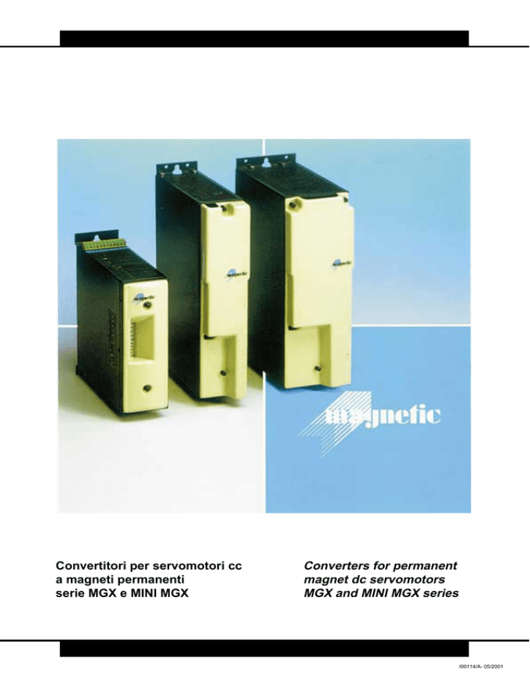
Convertitori per servomotori cc
a magneti permanenti
serie MGX e MINI MGX
Converters for permanent
magnet dc servomotors
MGX and MINI MGX series
I00114/A- 05/2001
Generalità
General Features
Trattasi di convertitori bidirezionali a quattro quadranti in tecnica
PWM adatti al controllo di servomotori a magneti permanenti in
c.c.; sia i convertitori della serie MGX che MINI MGX vengono forniti in configurazione monoasse.
Ogni modulo è completo del ponte raddrizzatore trifase con filtro,
del convertitore di potenza, del circuito alimentazioni ausiliarie e
del circuito di frenatura con relativa resistenza. Le due serie coprono una vasta gamma di potenze con correnti nominali da 4 a 50
Acc. e correnti massime da 8 a 150 Acc. Sono di facile installazione e con cablaggio facilitato dall’uso di morsettiere estraibili.
La ventilazione, quando è necessaria, è interna.
La tensione di alimentazione deve essere trifase ed ottenuta con
trasformatore avente il secondario collegato a triangolo. La serie
MGX ha una tensione di uscita massima di 200 Vcc., mentre la
serie MINI MGX è prevista su due tipologie (codice 3 o 9) che possono rispettivamente fornire una tensione di uscita massima di
130 Vcc. o 190 Vcc.
Per movimentazioni di carichi con notevole inerzia o in cicli di lavoro con frenature particolarmente gravose, è possibile l’utilizzo di
una resistenza di frenatura esterna dimensionata per l’applicazione specifica (consultare ufficio tecnico Magnetic).
MGX and MINI MGX converters are suitable to drive permanent
magnet D.C. servomotors; the regulation is in PWM mode and the
execution is in stand alone configuration.
Each module is complete of power supply, dc/dc convertor, ausiliary power supply, braking circuit and braking resistor. The two
series satisfy a wide range of applications with nominal current
from 4 to 50 Adc and max current from 8 to 150 Adc. Easy installation due to detachable plug-in terminals.
The fan is integrated, where it is requested.
The connection to the power supply can be made means of threephases transformer; the secondary of the transformer must be
connected in triangle mode. The MGX series is foreseen with max
output 200 Vdc, the MINI MGX series with max output 130 Vdc
(code 3) or 190 Vdc (code 9).
With considerable inertia charges it is possible to cut off the internal braking resistor and to use a external specific one (please contact our technical department).
Caratteristiche principali serie MGX
● Realizzazione monoasse completa di alimentatore di
potenza e circuito di frenatura con resistenza.
● Correnti nominali da 8 a 50 Acc. e correnti massime da 16 a
150 Acc.
● Corrente massima erogabile per 5 secondi.
● Corrente massima tarabile in funzione della velocità.
● Stadio di potenza a transistori ad elevata affidabilità.
● Basso rumore dovuto alla frequenza di switching pari a 5 KHz.
● Ingresso riferimento velocità differenziale.
● Ingresso riferimento di corrente per regolazioni di coppia.
● Ventilatore interno quando necessario.
● Reazione velocità da dinamo tachimetrica.
● Modulo estraibile frontalmente per la personalizzazione dei
seguenti parametri di taratura:
- rampa
- minima velocità
- limitazione della corrente in funzione della velocità
- guadagno dinamico
- costante derivata
- velocità fine
- offset
MGX series main features
● Stand alone execution complete of power supply, braking circuit
and braking resistor.
● Nominal currents from 8 to 50 Adc, max currents from 16 to
150 Adc.
● Max current available for 5 seconds.
● Max current adjustment with the speed.
● High reliability transistors power modules.
● Low noise due to the switching frequency of 5 KHz.
● Differential speed reference.
● Current reference for torque regulation.
● Integrated fan where requested.
● Speed feedback from tachogenerator.
● Front removable personality card with the following:
- acc./dev. ramp
- minimum speed
- max current with the speed
- dinamic gain
- derivative regulation
- maximun motor speed
- offset
Protections:
2
Motor thermal image ( I t - red LED on)
● Braking circuit overload (relay contact open)
Protezioni:
2
● Figura termica motore I t (LED rosso acceso per protezione
intervenuta).
● Sovraccarico circuito frenatura (contatto pulito aperto per protezione intervenuta).
●
Latched protections: (green LED off and relay contact open)
● Power supply overvoltage.
● Max/min BUS voltage.
● Heatsink overtemperature.
● Short circuit between motor connection or between motor and
ground.
● Tachogenerator loss or inverty connections.
● Internal circuit diagnostic (test connector for protection identification).
Protezioni memorizzate (LED verde spento e contatto pulito
aperto per protezioni intervenute):
● Sovraccarico alimentazioni.
● Massima/minima tensione BUS.
● Sovratemperatura radiatore convertitore.
● Cortocircuito collegamenti motore e/o tra motore e massa.
● Strappo tachimetrica o tachimetrica invertita.
● Diagnostica circuiteria interna (connettore di test per l’identificazione protezione intervenuta).
Accessori:
● Trasformatori trifasi di alimentazione.
● Induttanze esterne (vedere tabella).
● Resistenze frenatura esterne.
Optionals:
Power supply transformers.
● External inductances.
● External braking resistors.
●
2
Dati tecnici MGX
MGX Technical data
Tipo convertitore
Converter type
MGX
8/16
MGX
12/24
MGX
15/30
MGX
25/50
MGX
30/75
MGX
50/100
MGX
55/150
Corrente nominale (In)
Nominal current (In)
ADC
8
12
15
25
30
50
50
Corrente massima (Imax per 5”)
Max current (Imax = 5”)
ADC
16
24
30
50
75
100
150
Tensione alimentazione
Line to line supply voltage
VRMS
* 3x 110 ÷ 165
Frequenza alimentazione
Supply frequency
HZ
45 ÷ 65
Max tensione di uscita
Max output voltage
VDC
200
Tensione BUS intervento frenatura
Braking insertion BUS voltage
VDC
320
Frequenza chopper
PWM frequency
KHZ
5
Massimo segnale riferimento velocità
Max speed reference
VDC
±10 (20 kΩ input impedance)
Segnale riferimento corrente
Current signal reference
VDC
0 ÷ + 10
1.5
0.9
0.9
6.0
7.1
7.3
Rapporto regolazione velocità
Speed regulation
1 ÷ 5000
Massimo segnale tachimetrico
Max D.T. signal
VDC
± 100
Uscita tensioni ausiliarie
Auxliary voltage output
VDC
± 10 (5mA max)
Tempo rampa acc./dec.
Acc./dec. ramp time
s
0.01 ÷ 2
Minima induttanza carico
Min inductance of load
mH
Temperatura ambiente di lavoro
Ambient operating temperature
°C
Peso
Weight
kg
*
●
●
●
●
6
4
3
2
0 ÷ 40
3.5
3.7
5.3
5.8
Le tensioni di alimentazione dichiarate sono riferite a trasformatori a pieno carico e considerando una tolleranza di rete del ±10%.
Con trasformatori a vuoto, le tensioni di alimentazione non devono superare di +6V ac i dati di tabella a cui va aggiunta la tolleranza di rete del +10%.
The power supply suggested voltage is refered to loaded transformer output voltage with a further ±10% of tolerance on net value.
No load transformer output voltage must not exceed 187 Vrms (net tolerance included).
Dimensioni di ingombro MGX
MGX overall dimension
3
Vista frontale MGX
Frontal view MGX
Particolare scheda di personalizzazione
Customized setting card
MGX BLOCK DIAGRAM
SCHEMA A BLOCCHI MGX
4
Caratteristiche principali serie MINI MGX
● Realizzazione monoasse compatta completa di alimentatore di
potenza e circuito di frenatura con resistenza.
● Correnti nominali da 4 a 20 Acc. e correnti massime da 8 a
40 Acc.
● Corrente massima erogabile per 2 secondi.
● Schede con tecnologia SMT.
● Stadio di potenza a MOS-FET o IGBT.
● Bassissimo rumore dovuto alla frequenza di switching 20 KHz.
● Modulo di potenza estraibile.
● Ingresso differenziale riferimento velocità.
● Ingresso riferimento di corrente per regolazioni di coppia.
● Ventilatore interno quando necessario.
● Reazione velocità da dinamo tachimetrica.
● Regolazioni frontali:
- Velocità fine
- Offset
- Guadagno dinamico
- Costante derivata
- Rampa acc./dec.
MINI MGX series main features
● Stand alone execution complete of power supply, braking circuit and braking resistor.
● Nominal currents from 4 to 20 Adc., max currents from 8 to 40 Adc.
● Max current available for 2 seconds.
● SMT tecnology.
● IGBT or Power MOS-FET modules.
● Ultra low noise due to the switching frequency of 20 KHz.
● Removable power module.
● Differential speed reference.
● Current reference for torque regulation.
● Integrated fan where requested.
● Speed feedback from tachogenerator.
● Frontal adjustment:
- Maximum motor speed
- Offset
- Dinamic gain
- Derivative regulation
- Acc./dec. ramp
Protezioni (su unico contatto e visualizzate su LED separati):
2
● Figura termica motore I t.
● Massima/minima tensione di BUS.
● Sovratemperatura radiatore convertitore.
● Cortocircuito collegamenti motore e/o tra motore e massa.
● Strappo tachimetrica o tachimetrica invertita.
● Diagnostica circuiteria interna.
●
Accessori:
● Trasformatori trifasi di alimentazione.
● Induttanze esterne.
● Resistenze frenatura esterne.
Optionals:
● Power supply transformers.
● External inductances.
● External braking resistors.
Protections (single relay contact open but with different LEDS):
2
Motor thermal image (I t).
● Max/min BUS voltage.
● Heatsink overtemperature.
● Short circuit between motor connections or between motor and
ground.
● Tachogenerator loss or inverted connections.
● Internal circuits diagnostic.
Vista frontale MINI MGX
Frontal view MINI MGX
5
Dati tecnici MINI MGX
MINI MGX technical data
Tipo convertitore
Converter type
MINI 3 MINI 3 MINI 3 MINI 3 MINI 3 MINI 9 MINI 9 MINI 9 MINI 9 MINI 9
4/8
8/16
10/20 14/28 20/40
4/8
8/16
10/20 14/28 20/40
Corrente nominale (In)
Nominal current (In)
ADC
4
8
10
14
20
4
8
10
14
20
Corrente massima (Imax per 2”)
Max current (Imax = 2”)
ADC
8
16
20
28
40
8
16
20
28
40
Tensione alimentazione
Line to line supply voltage
VRMS
Frequenza alimentazione
Supply frequency
HZ
Max tensione di uscita
Max output voltage
VDC
130
190
Tensione BUS intervento frenatura
Braking insertion BUS voltage
VDC
173
268
Frequenza chopper
PWM frequency
KHZ
20
Massimo segnale riferimento velocità
Max speed reference
VDC
±10 (20 kΩ input impedance)
Segnale riferimento corrente
Corrent signal reference
VDC
0 ÷ + 10
3.2
3.3
* 3x 95
* 3x 140
45 ÷ 65
Rapporto regolazione velocità
Speed regulation
1 ÷ 5000
Uscita immagine di corrente (Imax)
Current signal output
VDC
± 8 (2mA max)
Uscita tensioni ausiliarie
Auxiliary voltage output
VDC
± 10 (5mA max)
Tempo rampa acc./dec.
Acc./dec. ramp time
s
0.1 ÷ 10
Minima induttanza carico
Min inductance of load
mH
1
Temperatura ambiente di lavoro
Ambient operating temperature
°C
0 ÷ 40
Peso
Weight
kg
*
2.6
2.8
●
Le tensioni di alimentazione dichiarate sono riferite a trasformatori a pieno carico e considerando una tolleranza di rete del ±10%.
● Con trasformatori a vuoto, le tensioni di alimentazione non devono
superare di +6V ac. i dati di tabella, a cui va aggiunta la tolleranza di
rete del +10%.
● The power supply suggested voltage is refered to loaded transformer output voltage with a further ±10% of tolerance on net value.
● No load transformer output voltage must not exceed respectively
110 or 160 Vrms (net tolerance included).
Scheda MINI MGX con componenti SMD
MINI MGX SMD components card
6
3.0
3.2
3.3
2.6
2.8
3.0
MINI MGX OVERALL DIMENSIONS
DIMENSIONI DI INGOMBRO MINI MGX
002408/0
MINI MGX BLOCK DIAGRAM
SCHEMA A BLOCCHI MINI MGX
7
PRODUCTION PROGRAM
DC Motors
DC Servomotors
Brushless Servomotors
Tachogenerators and centrifugal relays
DC servomotor convertors
Brushless servomotor convertors
Asynchronous vectorial motors
PROGRAMMA DI PRODUZIONE
Motori in corrente continua
Servomotori in corrente continua
Servomotori Brushless
Dinamo tachimetriche e Relè centrifughi
Convertitori per servomotori in C.C.
Convertitori per servomotori Brushless
Motori asincroni vettoriali
MAGNETIC SpA
Sede Amm.va e Stabilimento:
Via Fracanzana, 14
36054 Montebello Vicentino (VI) Italy
Tel. (0444) 649399
Fax (0444) 440495
E-mail: [email protected]
Web site: www.magneticspa.it
Le caratteristiche tecniche indicate in questo catalogo non sono impegnative e possono essere modificate senza preavviso./The above mentioned specifications are typical and subject to change without notice.

