RA
REATTANZE
REACTORS
componenti
components
La connessione delle reattanze in serie ai condensatori , crea un circuito oscillante con frequenza di
risonanza inferiore alla componente armonica più gravosa presente in rete, nella maggior parte dei
casi è di 5a armonica.
Il circuito serie così composto avrà la proprietà di essere induttivo sulle frequenze superiori a quelle
dell’accordo e quindi eviterà ulteriori risonanze.
Il fattore di accordo “p” definisce il rapporto percentuale tra la reattanza dell’induttanza XL e la reattanza della batteria di condensatori XC
p = 100 % *
XL
XC
e determina quindi la frequenza di risonanza “fA” tra reattanza dell’induttanza e batteria di condensatori
fA = fN *
I prodotti descritti sono suscettibili in qualsiasi momento di evoluzioni o di
modifiche. Le descrizioni ed i dati a catalogo non possono pertanto avere
alcun valore contrattuale.
Technical data and descriptions in the pubblication are accurate, to the
best of our knoweledge, but no liabilities for errors, omissions or contingencies arising therefrom are accepted.
100 %
p
Che è la frequenza di accordo del sistema reattanza-batteria condensatori.
Le reattanze tipo RA presentano per linee a 50 Hz una frequenza di accordo standard di 189 Hz
(p=7%), ma anche frequenze di accordo diverse come 134 Hz(p=14%) e 210 Hz(p=5.67%).
E’ importante far notare che l’inserimento delle reattanze di blocco armoniche in serie al condensatore causa un aumento di tensione sui condensatori; a seguire è riportata la formula per calcolare la
tensione sui condensatori “Uc”, in base alla tensione di rete “UN”alla tensione di grado inquinamento
armonico “Uh” e al fattore di accordo “p”
Un
UC = 1- P
100 %
+ Uh
La scelta della tensione nominale dei condensatori deve quindi essere condotta sulla base della nuova “Uc” e dal grado di inquinamento armonico presente in rete Uh. A seguire vi sono indicate in tabelle le principali tipologie di reattanze e le relative batterie di condensatori associabili.
TECNOLOGIA COSTRUTTIVA
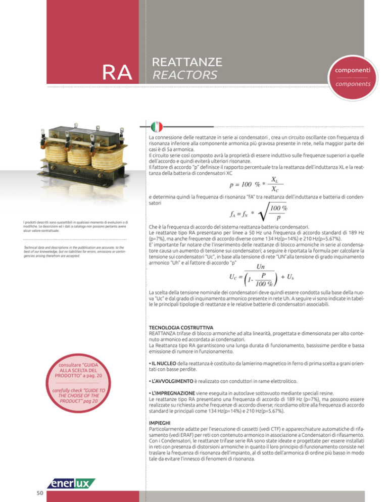
REATTANZA trifase di blocco armoniche ad alta linearità, progettata e dimensionata per alto contenuto armonico ed accordata ai condensatori.
La Reattanza tipo RA garantiscono una lunga durata di funzionamento, bassissime perdite e bassa
emissione di rumore in funzionamento.
consultare “GUIDA
ALLA SCELTA DEL
PRODOTTO” a pag. 20
carefully check “GUIDE TO
THE CHOISE OF THE
PRODUCT” pag 20
• IL NUCLEO della reattanza è costituito da lamierino magnetico in ferro di prima scelta a grani orientati con basse perdite.
• L’AVVOLGIMENTO è realizzato con conduttori in rame elettrolitico.
• L’IMPREGNAZIONE viene eseguita in autoclave sottovuoto mediante speciali resine.
Le reattanze tipo RA presentano una frequenza di accordo di 189 Hz (p=7%), ma possono essere
realizzate su richiesta anche frequenze di accordo diverse; ricordiamo oltre alla frequenza di accordo
standard le principali come 134 Hz(p=14%) e 210 Hz(p=5.67%).
IMPIEGHI
Particolarmente adatte per l’esecuzione di cassetti (vedi CTF) e apparecchiature automatiche di rifasamento (vedi ERAF) per reti con contenuto armonico in associazione a Condensatori di rifasamento.
Con i Condensatori, le reattanze trifase serie RA sono state ideate e progettate per essere installati
in reti con presenza di distorsioni armoniche in quanto il loro principio di funzionamento consiste nel
traslare la frequenza di risonanza dell’impianto, al di sotto dell’armonica di ordine più basso in modo
tale da evitare l’innesco di fenomeni di risonanza.
50
REATTANZE
REACTORS
RA
Series connection of the reactors to the capacitors, creates an oscillating circuit with a resonance frequency lower than worst harmonic component in the network; in most of the cases is the 5th harmonic.
The series circuit composed in this way will have the property to be inductive on the frequencies higher
than tuning ones, avoiding in this way further resonances.
The tuning factor “p” defines the percentage ratio of the XL inductance and the reactance of the capacitor
battery XC.
p = 100 % *
XL
XC
and determines also the resonance frequency “fA” between the reactance of the inductance and the capacitor battery.
fA = fN *
100 %
p
That is the tuning frequency of the reactor – capacitor battery system.
Reactors of RA type, have for the lines at 50Hz a standard tuning frequency of 189Hz (p=7%), but also
different tuning frequencies as 134Hz (p=14%) and 210Hz (P=5,57%).
It’s very important to remark that the installation in series of the harmonic blocking reactor to the capacitor causes an increase of the voltage on the capacitors; here below the formula to calculate the voltage on
the capacitors “Uc”, on the base of network voltage “Un”, the degree of harmonic pollution in the network
“Uh” and to the tuning frequency “p”.
Un
UC = 1- P
100 %
+ Uh
Thus, the choice of the rated voltage of capacitors must be made on the base of the new “Uc” and the
degree of harmonic pollution in the network”Uh. Here below the table with the main reactor types and
related capacitor batteries associated to them.
CONSTRUCTION TECHNOLOGY
Three-phase harmonic block REACTOR with high linearity, designed and sized for a high harmonic load and
tuned to the capacitors.
The RA-type Reactors ensure a lengthy service life, extremely low losses and low noise emission during operation.
• The CORE of the reactor consists of a magnetic plate made of top-grade iron with low-loss oriented grain
with low losses.
• The WINDING is made with electrolytic copper conductors.
• IMPREGNATION is done in vacuum autoclave with special resins.
The RA-type reactors have a tuning frequency of 189 Hz (p=7%), but other tuning frequencies can also be
made on request; of course, in addition to the standard tuning frequency the main ones are 134 Hz(p=14%)
and 210 Hz(p=5.67%).
USES
Especially suited to make modular units (see CTF) and automatic power factor correction equipment (see
ERAF) for networks with a harmonic load in association with power factor correction capacitors.
With the Capacitors, the RA series three-phase reactors have been conceived and designed to be installed
in networks with harmonic distortion since their working principle consists of translating the resonance
frequency of the installation under the harmonic of a lower magnitude so as to avoid triggering phenomena of resonance.
51
REATTANZE
REACTORS
RA
CODICE
REFERENCE
CORRENTE
INDUTTANZA NOMINALE
ACCORDO INDUCTANCE
RATED
DETUNING
(mH)
CURRENT
(Am5)
POTENZA
RESA
OUTPUT
(Kvar)
CONDENSATORE
TEORICA
PER COMPOSIZIONE CAPACITA’
PESO
BATTERIA
BATTERIA
WEIGHT
THEORICAL
CAPACITAN(Kg) CAPACITOR TO COMPOSE CE OF THE BATTERY
THE BATTERY
(uF)
(Kvar)
DIMENSIONI DI INGOMBRO
OVERALL DIMENSIONS
L
(mm)
B
(mm)
H
(mm)
RA.4012.189
3 x 3,07 22,1
12,5
240
130
150
11
PRT.4414
3 x 77
P=7%
RA.4025.189
3 x 1,53 44,1
25
240
140
190
16
PRT.4428
3 x 154
(189 Hz)
RA.4050.189
3 x 0,77
88
50
300
170
190
33
2 x PRT.4428
3 x 308
RA.4012.210
3 x 2,45 24,5
12,5
240
140
190
12
PRT.4414
3 x 77
P=5,67%
RA.4025.210
3 x 1,22
49
25
240
150
190
21
PRT.4428
3 x 154
(210 Hz)
RA.4050.210
3 x 0,61
98
50
300
170
200
42
2 x PRT.4428
3 x 308
RA.4012.134
3 x 6,63 22,3
12,5
240
140
190
19
PRT.5219
3 x 71,3
P=14%
RA.4025.134
3 x 3,32 44,6
25
300
170
190
39
PRT.5237
3 x 143
(134 Hz)
RA.4050.134
3 x 0,77 89,1
50
340
170
270
62
2 x PRT.5237
3 x 286
N.B. I dati sopra indicati si riferiscono per reti a 400V-50 Hz
Please note the data indicated above are referred to 400V-50Hz
CARATTERISTICHE TECNICHE
TECHNICAL PARTICULARS
Tensione nominale (Un)
Frequenza nominale
Rated voltage (Un)
400 V
Rated frequency
50 Hz (60 Hz a richiesta) - 50 Hz (60 Hz on request)
Linearità
Linearity
2 In
Tolleranza sull’induttanza
±3%
Temperatura ambiente
+ 40° C
Ambient temperature
Max sovratemperatura di funzionamento
+ 60° C
Max. operating overtemperature
Max distorsione armonica in corrente ammessa in
funzionamento continuativo per reattanze con p=7%
Max distorsione armonica
(in tensione) ammessa in
funzionamento continuativo
3 % In a 150 Hz
35 % In a 250 Hz
15 % In a 350 Hz
5 % In a 550 Hz
Tolerance on the inductance
Max harmonic distortion in current permitted in
continuous operation for p=7% reactors
Max harmonic distortion
(in voltage) permitted in
continuous operation
1.05 Un
Corrente di saturazione
Saturation current
2 In
Classe Isolamento
Insulation class
H
Livello isolamento tra nucleo e avvolgimento
3 kV
Level of insulation between core and winding
Servizio
Continuo
Service
Installazione
Continuo
Installation
Raffreddamento
Cooling
Aria naturale o forzata
Grado di protezione
Degree of protection
IP00
Fissaggio
Fixing
Tramite asole su staffe di base
Norme di riferimento
Reference standards
CEI 14-5, IEC 60238
Altre caratteristiche realizzabili su richiesta.
Other characteristics can be made on request.
H±2
H±2
Capicorda M8
M8 cable terminal
Bullone M6
M6 bolt
L±2
52
B-40 ± 2
L±2
B ±2
Asola di fissaggio
Fixing slot
8
25
L-50 ± 2

