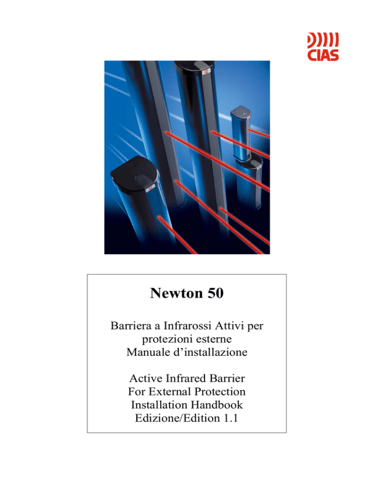
Newton 50
Barriera a Infrarossi Attivi per
protezioni esterne
Manuale d’installazione
Active Infrared Barrier
For External Protection
Installation Handbook
Edizione/Edition 1.1
® CIAS Elettronica S.r.l.
Ed. 1.1
INDICE
1. DESCRIZIONE
2
2. CARATTERISTICHE PRINCIPALI
2
3. AVVERTENZE PER L’INSTALLAZIONE
4
4. INSTALLAZIONE
5
4.1 Rimozione del coperchio
5
4.2 Montaggio del coperchio
6
4.3 Montaggio a parete
6
4.4 Montaggio a palo
7
5. COLLEGAMENTI
8
5.1 Collegamento del Trasmettitore
8
5.2 Collegamento del Ricevitore
8
5.3 Lunghezza dei cavi di alimentazione dei moduli a 13,8 Vcc
9
5.4 Lunghezza dei cavi di alimentazione per il riscaldamento a 12 Vcc o Vca
9
6. ALLINEAMENTO E REGOLAZIONI
10
6.1 Allineamento ottico
10
6.2 Selezione dei canali
11
6.3 Ottimizzazione elettronica dell’allineamento
12
6.4 Ottimizzazione del tempo di risposta
13
7. CONTROLLO FINALE
14
8. MANUTENZIONE
14
9. CARATTERISTICHE TECNICHE
15
10. NEWTON TOWER
16
Manuale d’installazione/ Installation Manual
Pag. 1 / 39
Newton 50
® CIAS Elettronica S.r.l.
Ed. 1.1
1. DESCRIZIONE
Le barriere a raggi infrarossi attivi con emissione quadrupla Newton 50 sono composte da
un Trasmettitore e un Ricevitore installati uno di fronte all’altro, ad ogni estremità della
tratta protetta, creando così un’invisibile zona di protezione. Esse generano un allarme
qualora entrambi i doppi raggi ottici a infrarossi sono interrotti contemporaneamente da un
tentativo di intrusione. L’elaborazione elettronica di cui sono dotate queste barriere le
rende insensibili agli uccelli, piccoli animali, foglie che cadono.
Per evitare disturbi tra barriere Newton adiacenti vi è la possibilità di selezionare diversi
canali di modulazione senza l’utilizzo di alcun tipo di collegamento per la sincronizzazione
(sincronizzazione ottica).
- Un Trasmettitore è composto da 2 moduli ottici Tx e 1 modulo elettronico Tx.
- Un Ricevitore è composto da 2 moduli ottici Rx e 1 modulo elettronico Rx.
2. CARATTERISTICHE PRINCIPALI
Massima portata per uso in esterno:
NEWTON 50 = 50m
Quattro frequenze selezionabili per modulazione ad impulsi del segnale infrarosso.
Quadri emissione (due Moduli Ottici Trasmettitori che emettono due raggi ciascuno).
Alta immunità alle condizioni atmosferiche pessime e verso allarmi indesiderati,
grazie all’analisi dello stato dei 4 raggi che devono essere interrotti simultaneamente
per generare un segnale d’allarme. L’immunità dipende anche dal tempo di
rivelazione d’allarme, regolabile e adattabile ad ogni particolare situazione.
Metodo integrato d’allineamento: puntatore ottico, led indicatori, punto di misura del
segnale.
Sistema di riscaldamento con termostato, incluso in ogni colonna sia trasmittente
che ricevente, per anticongelamento e antiappannamento.
Protezione verso apertura del coperchio.
Struttura ad alta resistenza agli urti e ad agenti corrosivi.
Manuale d’installazione/ Installation Manual
Pag. 2 / 39
Newton 50
® CIAS Elettronica S.r.l.
Ed. 1.1
NEWTON 50
Piattello di copertrura
Modulo Ottico
Trasmettitore
a doppia emissione o
Modulo Ottico Ricevitore
Foro sigillato con tappo
di gomma per Vite
di fissaggio a parete
Morsettiera di
collegamento
Modulo Elettronico
Tx o Rx
Modulo Ottico
Trasmettitore
a doppia emissione o
Modulo Ottico Ricevitore
Incastellatura
di alluminio
Resistenze
con Termostato
e morsettiera per ingresso
alimentazione
del riscaldamento
Foro sigillato con tappo
di gomma per Vite
di fissaggio a parete
Piattello inferiore
ACCESSORI FORNITI
2 Maschere d’allineamento
1 Manuale di installazione
figura 1
Manuale d’installazione/ Installation Manual
Pag. 3 / 39
Newton 50
® CIAS Elettronica S.r.l.
Ed. 1.1
3. AVVERTENZE PER L’INSTALLAZIONE
Per una corretta installazione delle barriere Newton, è necessario attenersi alle seguenti
regole:
Non posizionare i ricevitori in modo tale che la luce solare, diretta o riflessa,
possa raggiungerli. Infatti se la luce solare, colpisse direttamente o per riflessione i
ricevitori, potrebbero manifestarsi falsi allarmi.
Non posizionare la barriera Newton accostata a superfici altamente riflettenti,
quali pareti bianche o addirittura vetrate, potrebbero, in questo caso, verificarsi
fenomeni di insensibilità della barriera (difficoltà a generare un allarme).
Non posizionare la barriera Newton su supporti meccanicamente instabili, quali
recinzioni che possono muoversi, pali male ancorati, in questi casi, potrebbero
verificarsi disallineamenti della barriera con conseguente generazione di falsi
allarmi.
RICEVITORE
Angolo
min. 5°
TRASMETTITORE
CANALE 2
CANALE 1
Manuale d’installazione/ Installation Manual
Pag. 4 / 39
Newton 50
® CIAS Elettronica S.r.l.
Ed. 1.1
Assicurarsi che lungo la tratta protetta dalla barriera Newton, non ci sia alcun tipo
di vegetazione, e se dovesse esserci la possibilità che essa cresca, avvisare
l’utente che deve procedere ad una accurata manutenzione ed estirpare la
vegetazione indesiderata che dovesse comunque crescere. In caso contrario
potrebbe verificarsi l’insorgenza di falsi allarmi.
Assicurarsi che utilizzando due o più barriere Newton lungo la stessa tratta, i
canali selezionati per ciascuna siano differenti. Qualora i canali selezionati fossero
uguali, potrebbero verificarsi fenomeni di instabilità con conseguente generazione
di falsi allarmi o di insensibilità.
Provvedere sempre ad alimentare i riscaldatori antigelo e antiappannamento,
fornendo una tensione di alimentazione di 12 V nominali in corrente continua o in
corrente alternata, sugli appositi morsetti. Non utilizzare per questo scopo, la stessa
linea di alimentazione utilizzata per alimentare i moduli elettronici Tx o Rx. In caso
contrario l’entrata in funzione dei riscaldatori potrebbe influenzare negativamente
l’alimentazione dei moduli con conseguente possibile generazione di falsi allarmi.
Porre particolare attenzione al dimensionamento dei conduttori delle linee di
alimentazione sia dei moduli IR che dei riscaldatori. Un’inadeguata sezione dei
conduttori di alimentazione dei moduli IR o dei riscaldatori può essere la causa
della generazione di falsi allarmi.
4. INSTALLAZIONE
Le barriere Newton possono essere installate direttamente su pareti in muratura o su pali
di sostegno. Requisito indispensabile è la stabilità del sostegno.
4.1 Rimozione del coperchio
Per rimuovere il coperchio della barriera Newton, occorre svitare la vite che lo fissa al
piattello inferiore fare scorrere il coperchio di qualche cm verso il basso agendo come
mostrato nella figura sottoriportata, quindi tirare il coperchio stesso dalla base verso
l’esterno.
Manuale d’installazione/ Installation Manual
Pag. 5 / 39
Newton 50
® CIAS Elettronica S.r.l.
Ed. 1.1
4.2 Montaggio del coperchio
Per rimontare il coperchio, inserirlo con la parte bassa qualche cm sotto il piattello inferiore
in modo che si posizioni nelle guide del profilato d’alluminio che costituisce l’incastellatura,
spingere il coperchio dal basso verso l’alto, in modo che scorrendo nelle guide si inserisca
nel piattello superiore, poi avvitare la vite di fissaggio.
4.3 Montaggio a parete
Praticare sulla parete i fori per i tasselli da muro, secondo lo schema di foratura illustrato in
figura.
PARETE
Tassello da muro
228,0 mm
Vite di fissaggio
40,0 mm
Vite di fissaggio
Dopo aver tolto i coperchi rimuovere i sigilli in gomma che chiudono i due fori di fissaggio
presenti in ciascuna colonna. Attraverso questi fori devono essere fatte passare le viti di
fissaggio.
Manuale d’installazione/ Installation Manual
Pag. 6 / 39
Newton 50
® CIAS Elettronica S.r.l.
Ed. 1.1
4.4 Montaggio a palo
Dopo aver fissato il palo (SPS 1) alle viti, sporgenti dalla fondazione in cemento, mediante
gli appositi dadi, togliere i coperchi della barriera, rimuovere i sigilli in gomma che
chiudono i due fori di fissaggio presenti in ciascuna colonna. Posizionare le due staffe
metalliche (opzionali) in corrispondenza di questi fori mediante le viti fornite insieme ad
esse. Infilare dall’alto le due staffe e posizionare la colonna Newton all’altezza desiderata,
quindi stringere le viti di fissaggio e serrare opportunamente il dado in modo che la
colonna resti bloccata.
BASE PALO
(SPS1)
GANASCIA PER
PALO
60 x 30 mm
GANASCIA PER
PALO
60 x 30 mm
PALO
60 x 30 mm
INCASTELLATURA
DI ALLUMINIO
COPERCHIO
NEWTON 50
VITI DI FISSAGGIO
Manuale d’installazione/ Installation Manual
Pag. 7 / 39
Newton 50
® CIAS Elettronica S.r.l.
Ed. 1.1
5. COLLEGAMENTI
Per accedere con il cavo all’interno, impiegare il passacavo posto sul fondo dell’unità,
sono necessarie alcune precauzioni per assicurare la tenuta all’acqua ed evitare
infiltrazioni lungo il cavo.
5.1 Collegamento del Trasmettitore
Di seguito è rappresentata la morsettiera del modulo Trasmettitore
L’alimentazione relativa al sistema di riscaldamento, deve essere connessa all’apposita
morsettiera e deve essere realizzata con una linea di alimentazione separata, rispetto a
quella di alimentazione del modulo. Tale alimentazione può essere realizzata sia mediante
tensione continua sia mediante tensione alternata.
Morsetto N°
12 V
DC
POWER
1
2
3
4
TAMPER
Funzione
+ 13,8 V Alimentazione
GND 0
Alimentazione
Contatto Tamper
Contatto Tamper
5.2 Collegamento del Ricevitore
Di seguito è rappresentata la morsettiera del modulo Ricevitore.
L’alimentazione relativa al sistema di riscaldamento, deve essere connessa all’apposita
morsettiera e deve essere realizzata con una linea di alimentazione separata, rispetto a
quella di alimentazione del modulo. Tale alimentazione può essere realizzata sia mediante
tensione continua sia mediante tensione alternata.
12 V
DC
POWER
NO
TAMPER
C
NC
ALARM CONTACTS
Morsetto N°
1
2
3
4
5
6
7
Manuale d’installazione/ Installation Manual
Pag. 8 / 39
Funzione
+ 13,8 V Alimentazione
GND 0 V Alimentazione
Contatto Tamper
Contatto Tamper
Contatto di Allarme NO
Contatto di Allarme C
Contatto di Allarme NC
Newton 50
® CIAS Elettronica S.r.l.
Ed. 1.1
5.3 Lunghezza dei cavi di alimentazione dei moduli a 13,8 Vcc
Di seguito viene riportata una tabella che indica in funzione della lunghezza dei conduttori
la sezione minima impiegabile. I conduttori devono essere di tipo schermato ed intrecciato.
Diametro Sezione
conduttori conduttori
[mm]
[mm2]
0,6
0,9
1,4
0,3
0,6
1,5
Lunghezza dei conduttori
[m]
NEWTON 50
Tx
Rx
Tx +Rx
500
1100
2500
135
300
700
100
250
550
5.4 Lunghezza dei cavi di alimentazione per il riscaldamento a 12 Vcc o Vca
Di seguito viene riportata una tabella che indica in funzione della lunghezza dei conduttori
la sezione minima impiegabile. I conduttori devono essere di tipo schermato ed intrecciato.
Diametro
conduttori
[mm]
0,6
0,9
1,4
1,8
2,3
2,8
Sezione
conduttori
[mm2]
0,3
0,6
1,5
2,5
4
6
Lunghezza dei conduttori
[m]
NEWTON 50
Tx
Rx
Tx +Rx
40
80
190
300
500
750
40
80
190
300
500
750
20
40
95
150
250
400
Nota: Utilizzando lo stesso cavo per alimentare più barriere Newton le distanze indicate
devono essere divise per il numero di barriere collegate.
Manuale d’installazione/ Installation Manual
Pag. 9 / 39
Newton 50
® CIAS Elettronica S.r.l.
Ed. 1.1
6. ALLINEAMENTO E REGOLAZIONI
Porre molta attenzione all’allineamento dei moduli ottici, poiché da ciò dipende in modo
preponderante il buon funzionamento delle barriere.
6.1 Allineamento ottico
L’allineamento ottico consiste nel far coincidere gli assi dei moduli ottici trasmettitori e
ricevitori. Questo allineamento fondamentale deve essere fatto per ognuna delle due
coppie di moduli ottici utilizzando il sistema di puntamento integrato.
Tx
Rx
Modulo ottico
Trasmettitore
Modulo ottico
Ricevitore
Descrizione dell’allineamento ottico dei moduli
Ai due lati del modulo ottico, si trovano due fori che fungono da visore per
l’allineamento. Accostando l’occhio a circa 5 cm da uno di questi fori, è possibile
inquadrare, attraverso un sistema di specchi interni e dei due mirini anteriori, la
scena nella direzione verso la quale è diretto il modulo.
Regolare la posizione sul piano orizzontale sino a visualizzare la colonna
corrispondente.
Regolare ora, la posizione verticale, fino ad ottenere il perfetto inquadramento del
proprio modulo ottico posto nella corrispondente colonna.
Ripetere l’operazione con il secondo modulo ottico.
Portarsi alla corrispondente colonna e ripetere le operazioni precedenti.
Manuale d’installazione/ Installation Manual
Pag. 10 / 39
Newton 50
® CIAS Elettronica S.r.l.
Ed. 1.1
Modulo ottico
Regolazione
Verticale
+/- 10°
Immagine Visualizzata
attraverso il mirino
dopo un buon allineamento
Foro visore
laterale
Mirini frontali per
l’allineamento ottico
Regolazione
Orizzontale
+/- 90°
6.2 Selezione dei canali
Prima di alimentare la barriera Newton, è necessario accertarsi che il numero di canale
impostato sul modulo elettronico Trasmettitore sia il medesimo di quello impostato sul
modulo elettronico Ricevitore. Qualora i canali impostati su Ricevitore e Trasmettitore non
corrispondessero, la barriera non può funzionare, se ciò accadesse, disalimentare,
cambiare il numero di canale, quindi rialimentare.
La selezione del canale si effettua sia sul modulo elettronico Trasmettitore che sul modulo
elettronico Ricevitore, mediante l’apposito “dip-switch” come mostrato in figura.
DIP-SWITCH PER SELEZIONE CANALE
1
ON
2
1
2
ON
C9
5
6
2
TAMPER
R17
R5
AP1
CANALE 4
1
POWER
MODULO ELETTRONICO
TRASMETTITORE
PT1
1
C10
CANALE 3
ON
Manuale d’installazione/ Installation Manual
C4
R1
C3
MODULO ELETTRONICO
RICEVITORE
P5
P4
P3
P2
P1
ALARM CONTACTS
CI1
TAMPER
4
PT4
POWER
2 12 V3
DC
1
POWER TAMPER HEATER
R2
NC
R3
10
R9
9
R7
R8
8
C
NO
DISQ. HEATER
G1
7
C12
6
C11
5
CI3
4
Morsettiera di
12V
Collegamento
C7
3
12V
DC
2
G3
2
R6
1
12 V
POWER
DCTAMPER ALARM
1
G2
2
ON
CANALE 2
12V
Morsettiera di Collegamento
12V
DC
R12 R11
C8 PT2 R10
1
BORNIER DE RACCORDEMENT
ON
C14
SW1
ON
2
C15 R16
1
CANALE 1
1
BORNIER DE RACCORDEMENT
SW1
ON
2
ON
2
Pag. 11 / 39
Newton 50
® CIAS Elettronica S.r.l.
Ed. 1.1
L’utilizzo di differenti canali consente di installare più barriere Newton sovrapposte (max 4)
senza alcuna necessità di utilizzo di cavi di sincronismo e senza alcun tipo di interferenza
reciproca (sincronismo ottico). Nella figura sono presentati 2 casi in cui l’utilizzo di
differenti canali, consente di installare più barriere Newton senza che esse si
interferiscano.
TRASMETTITORE
CANALE 2
RICEVITORE
TRASMETTITORE
CANALE 1
RICEVITORE
RICEVITORE
CANALE 1
TRASMETTITORE
TRASMETTITORE
CANALE 1
RICEVITORE
RICEVITORE
CANALE 2
TRASMETTITORE
6.3 Ottimizzazione elettronica dell’allineamento
Dopo aver effettuato l’allineamento per mezzo dei visori e dei mirini incorporati in ciascun
gruppo ottico, e dopo aver alimentato la barriera Newton, si verificherà la seguente
situazione:
Il LED verde, presente sul modulo elettronico Trasmettitore, è acceso indicando che
esso è alimentato ed il Trasmettitore è attivo.
Il LED Rosso presente sul modulo elettronico Ricevitore è Spento indicando che
esso riceve un segnale infrarosso di intensità superiore al minimo indispensabile.
Per ottimizzare l’allineamento, utilizzando il sistema elettronico incorporato, procedere
come segue:
Utilizzando le due mascherine nere di cui ogni barriera Newton è dotata, occludere
i due moduli ottici Tx ed Rx superiori.
Inserire i puntali di un voltmetro negli appositi punti di misura presenti sul
Ricevitore.
Regolare l’orientamento dei due moduli ottici Tx ed Rx inferiori, in modo che la
tensione letta con il voltmetro raggiunga il valore massimo possibile.
Manuale d’installazione/ Installation Manual
Pag. 12 / 39
Newton 50
® CIAS Elettronica S.r.l.
Ed. 1.1
Rimuovere le mascherine dai moduli ottici superiori, ed applicarle a quelli inferiori,
facendo attenzione a non alterarne l’orientamento ottimizzato.
Regolare l’orientamento dei due moduli ottici Tx ed Rx superiori, in modo che la
tensione letta con il voltmetro raggiunga il valore massimo possibile.
Rimuovere le mascherine anche dai moduli ottici inferiori, facendo attenzione a non
alterarne l’orientamento ottimizzato. La tensione letta sul voltmetro fornisce una
misura della qualità dell’allineamento. La tabella seguente riporta questa
valutazione.
Tensione Misurata
Qualità dell’allineamento
>3V
da 1,5 a 3 V
< 1,5 V
Eccellente
Buona
Cattiva
6.4 Ottimizzazione del tempo di risposta
Il tempo di risposta, regolabile mediante il potenziometro “Response Time” posto sul
modulo elettronico Ricevitore, può assumere valori che vanno da 50 a 800 ms. questa
regolazione consente di ottimizzare la sensibilità di rivelazione ad ogni particolare
condizione di installazione. Aumentando il tempo di risposta, diminuisce la sensibilità.
Manuale d’installazione/ Installation Manual
Pag. 13 / 39
Newton 50
® CIAS Elettronica S.r.l.
Ed. 1.1
7. CONTROLLO FINALE
Ad installazione completata eseguire le seguenti verifiche:
Verificare che l’attraversamento della barriera produca una segnalazione di allarme
intrusione.
Accertarsi che i coperchi siano puliti
Ripetere almeno annualmente il controllo finale con particolare riguardo alla pulizia dei
coperchi. È consigliabile inoltre annotare ad ogni intervento il valore della tensione di
allineamento, in modo da poter rilevare per tempo eventuali degradi ed evitare falsi
allarmi.
8. MANUTENZIONE
La tabella che segue riporta l’elenco dei malfunzionamenti più comuni, con la probabile
causa che li determina e l’indicazione della soluzione.
Malfunzionamento
Probabile Causa
LED verde Tx spento
-Alimentazione non corretta
Raggi IR interrotti ma LED -Raggi IR non interrotti
rosso Rx spento
contemporaneamente
-Raggi IR riflessi da una
superficie adiacente (Vetro,
Acqua…)
e
quindi
interruzione solo apparente
-Il Ricevitore si trova nel
campo
trasmissivo
di
un’altra barriera
LED rosso Rx sempre -Alimentazione non corretta
acceso
-Tx sconnesso
-Errato allineamento
-Canali differenti
-Raggi IR ostruiti
Falsi allarmi
-Cattivo allineamento
-Alimentazione non corretta
Manuale d’installazione/ Installation Manual
Pag. 14 / 39
Soluzione
-Verificare alimentazione
-Interrompere i raggi IR
contemporaneamente
-Verificare la correttezza
dell’installazione
(Posizionamento)
-Verificare la correttezza
dell’installazione
(Posizionamento)
-Verificare alimentazione
-Connettere Tx
-Ripetere l’allineamento
-Modificare il canale
-Eliminare l’ostruzione
-Ricontrollare l’allineamento
- Verificare i cablaggi ed il
dimensionamento
dei
conduttori.
Newton 50
® CIAS Elettronica S.r.l.
Ed. 1.1
9. CARATTERISTICHE TECNICHE
NEWTON 50
Lunghezza d’onda usata
Distanza massima interno
Distanza massima esterno
Numero raggi IR emessi
Numero canali modulazione
Modalità rivelazione
Tempo risposta allarme
Durata allarme intrusione
Tensione di alimentazione
Assorbimento di corrente:
Barriera
Solo Ricevitore
Solo Trasmettitore
Alimentazione riscaldatore
Assorbimento di corrente
riscaldamento:
Barriera
Solo Ricevitore
Solo Trasmettitore
Tamper Tx ed Rx
Allarme intrusione Rx
Orientabilità moduli ottici
Sistema di allineamento
Temperatura di utilizzo
Grado di protezione contenitori
Dimensioni Esterne di una colonna
Peso Tx+Rx in scatola
Compatibilità Elettromagnetica
Manuale d’installazione/ Installation Manual
950 nm
125 m
50 m
4
4
Interruzione contemporanea dei 4 raggi
Regolabile da 50 a 800 ms
4 sec. + tempo interruzione raggi
Da 10 a 15 V
45 mA
30 mA
15 mA
Da 10 a 15 V
o V∼
340 mA
170 mA
170 mA
Contatto Normalmente Chiuso 0,5 A
Scambio completo 0,5 A
Orizzontale: +/- 90°; Verticale: +/- 10°
Visore ottico + punti di misura per ottimizzazione
elettronica e misura qualità
-25 +55 °C
IP 54
H= 340 mm; L=74 mm; P=81 mm
1,5 Kg
Conforme ai requisiti essenziali della direttiva
EMC 89/336/CEE
Pag. 15 / 39
Newton 50
® CIAS Elettronica S.r.l.
Ed. 1.1
10, NEWTON TOWER
Le colonne Newton Tower, vengono fornite in tre differenti altezze:
NEWTON TOW 1 = 110 cm
NEWTON TOW 2 = 190 cm
NEWTON TOW 3 = 300 cm
Queste colonne possono essere fissate direttamente a parete, mediante le viti, i distanziali
ed i tasselli in plastica contenute in ciascuna confezione, utilizzando gli appositi fori,
sigillati con tappi in gomma, predisposti nell’incastellatura in alluminio.
Esse possono essere fissate al suolo mediante i pali di sostegno in acciaio verniciato:
NEWTON SPB1 Altezza 110 cm per NEWTON TOW 1 e 2
NEWTON SPB2 Altezza 200 cm per NEWTON TOW 3
Il fissaggio delle colonne a questi pali, può essere effettuato tramite le apposite viti a testa
esagonale che devono essere montate nelle due guide posteriori dell’incastellatura di
alluminio assieme ai distanziali in plastica e poi fatte passare attraverso i fori predisposti
sui pali.
Dado 5 MA
MONTAGGIO SU PALO
Colonna
Vite 5 x 70
Rondella
d = 5mm
Palo
SPB1-2
Distanziali
Le colonne Newton Tower 1 - 2 - 3 sono provviste di un passacavo montato sotto il
piattello inferiore e di un micro interruttore a levetta azionato dalla vite che assicura la
chiusura del coperchio situata sul piattello inferiore, fornendo così l’informazione di
tamper.
In ciascuna colonna possono essere alloggiati uno o più Kit di trasmissione e/o ricezione.
Questi kit sono composti da due moduli ottici trasmittenti o riceventi, e da un modulo
elettronico di trasmissione o ricezione, e precisamente:
NEWTON 50 RX
NEWTON 50 TX
Per ciascuno di questi Kit vengono fornite le viti di fissaggio all’incastellatura di alluminio, i
due cavetti di collegamento tra moduli ottici e modulo elettronico provvisti degli appositi
connettori, le mascherine per effettuare l’ottimizzazione elettronica dell’allineamento, il
circuito di riscaldamento termostatato che è separato dai moduli ottici, viti e distanziali per
il suo montaggio, ed inoltre, poiché tali moduli sono più piccoli di quelli da 100 e 200 m,
vengono forniti anche particolari meccanici e viti che ne consentono il montaggio in queste
colonne.
Manuale d’installazione/ Installation Manual
Pag. 16 / 39
Newton 50
® CIAS Elettronica S.r.l.
Ed. 1.1
Nelle figure seguenti, sono mostrati i particolari salienti dei moduli ottici ed elettronici e la
loro collocazione in una colonna.
Colonna NEWTON TOW 1 – 2 – 3 assemblata e parti costituenti il Kit Tx o Rx
Modulo Ottico
Modulo Elettronico
Modulo Ottico
Kit Alimentazione
Newton Alim
Batteria
“Tampone”
Modulo Ottico
Modulo Elettronico
Modulo Ottico
Microinterruttore
Tamper
Descrizione
1
2
3
4
5
6
7
8
9
10
11
Manuale d’installazione/ Installation Manual
Pag. 17 / 39
Modulo Ottico Ricevitore
Modulo Ottico Trasmettitore
Modulo Elettronico Ricevitore
Modulo Elettronico Trasmettitore
Morsettiera Estraibile Rx
Morsettiera Estraibile Tx
Viti fissaggio Moduli Elettronici
Viti fissaggio Moduli Ottici
Cavetto di interconnessione Moduli
Mascherine per Allineamento
Elettronico
Manuale di assemblaggio e
installazione
Newton 50
® CIAS Elettronica S.r.l.
Ed. 1.1
Di seguito è riportata la sequenza di assemblaggio dei kit Tx o Rx nelle colonne Newton
Tower.
7
Manuale d’installazione/ Installation Manual
Pag. 18 / 39
Newton 50
® CIAS Elettronica S.r.l.
Ed. 1.1
Per alimentare questi moduli e relativi sistemi di riscaldamento, è possibile impiegare il Kit
di alimentazione NEWTON ALIM che è costituito da un alimentatore carica batteria
provvisto di una uscita per la carica di una batteria per l’alimentazione in assenza di rete
dei moduli, di una uscita per la alimentazione dei moduli, e di una uscita per
l’alimentazione del sistema di riscaldamento in presenza di rete. Il kit di alimentazione è
costituito anche da una staffa per il fissaggio all’incastellatura di alluminio di una batteria
da 1,2 Ah e delle viti per il fissaggio sia dell’alimentatore che della staffa.
Manuale d’installazione/ Installation Manual
Pag. 19 / 39
Newton 50
® CIAS Elettronica S.r.l.
Ed. 1.1
INDEX
1. DESCRIPTION
21
2. MAIN CHARACTERISTICS
21
3. INSTALLATION HINTS
23
4. INSTALLATION
24
4.1 Removal of the cover
24
4.2 Mounting the cover
25
4.3 Wall mounting
25
4.4 Pole mounting
26
5. CONNECTIONS
27
5.1 Transmitter connection
27
5.2 Receiver connection
27
5.3 Length of the 13.8Vdc power supply cables used for the modules
28
5.4 Length of the 12 Vdc/Vac power supply cables used for heating
28
6. ALIGNMENT AND ADJUSTMENT
29
6.1 Optical alignment
29
6.2 Channel selection
30
6.3 Electronic alignment optimization
31
6.4 Optimisation of the response time
32
7. FINAL INSPECTION
33
8. TROUBLESHOOTING
33
9. TECHNICAL CHARACTERISTIC
34
10. NEWTON TOWER
35
Manuale d’installazione/ Installation Manual
Pag. 20 / 39
Newton 50
® CIAS Elettronica S.r.l.
Ed. 1.1
1. DESCRIPTION
The active infra-red rays barriers with quadruple emission Newton 50 consist of a
Transmitter and of a Receiver installed one facing the other at each end of the protected
section thus creating an invisible protection zone. They generate an alarm whenever both
of the dual optical infra-red rays are simultaneously interrupted following an attempt to
intrude the zone. The electronic processing with which these barriers are provided makes
them insensitive to birds, small animals and falling leaves.
To prevent disturbance between adjacent Newton barriers there is the possibility of
selecting different modulation channels without using any type of connection for
synchronization (optical synchronisation).
- One Transmitter consists of 2 Tx optical modules and 1 Tx electronic module.
- One Receiver consists of 2 Rx optical modules and 1 Rx electronic module.
2. MAIN CHARACTERISTICS
Maximum coverage for outdoor use:
NEWTON 50 = 50m
Four selectable frequencies for the infrared signal pulse modulation.
Emission Frames (two Tx Optical Modules each emitting two rays).
High immunity to adverse weather conditions and towards unwanted alarms, thanks
to the analysis of the state of the 4 rays that must be simultaneously interrupted in
order to generate an alarm signal. Immunity also depends on the time taken to
detect the alarm which, based on each particular circumstance, can be adjusted and
adapted accordingly.
Alignment integrated technique: optical pointer, indicating LEDs, signal test point.
Heating system with thermostat, included on each Tx and Rx module, used to thaw
and defog.
Cover opening protection.
Structure highly resistant to impacts and corrosive agents.
Manuale d’installazione/ Installation Manual
Pag. 21 / 39
Newton 50
® CIAS Elettronica S.r.l.
Ed. 1.1
NEWTON 50
Top cover plate
Double emission
Transmitter optic module
Or Receiver optic module
Sealed holes with rubber taps
for wall mounting screws
Terminal block
Electronic module
Tx or Rx
Double emission
Transmitter optic module
Or Receiver optic module
Rack aluminium frame
Heater resistor wit thermostat
And related power
Sealed holes with
rubber taps for wall
mounting screws
Bottom plate
SUPPLIED ACCESSORIES
2 Alignment plates
1 Installation Handbook
figure 1
Manuale d’installazione/ Installation Manual
Pag. 22 / 39
Newton 50
® CIAS Elettronica S.r.l.
Ed. 1.1
3. INSTALLATION HINTS
To properly install the Newton barriers observe the following rules:
Do not place the receivers in such a way that either direct or reflected sun-light
reaches them. In fact, false alarms might arise if the sun-light either directly hits or
reflects on the receivers.
Do not place the Newton barrier near highly reflecting surfaces, such as white
walls or glass panes, which might cause barrier insensitivity (difficulty to generate
an alarm).
Do not place the Newton barrier on unsteady mechanical supports, such as
fences that might move, or on badly anchored poles. In these cases, the barrier
might misalign with subsequent generation of false alarms.
RECEIVER
RICEVITORE
Manuale d’installazione/ Installation Manual
Min.
Angolo
min.
5° 5°
Angle
Pag. 23 / 39
TRANSMITTER
TRASMETTITORE
CHANNEL
CANALE
2
1
CANALE
1
CHANNEL
2
Newton 50
® CIAS Elettronica S.r.l.
Ed. 1.1
Make sure that along the section protected by the Newton barrier there is no type
of vegetation, and should it be likely to grow inform the user that he must be in
charge of its care and eventually uproot the unwanted grown vegetation. If
otherwise false alarms might arise.
Make sure that when two or more Newton barriers are used along the same section
the different channels must be selected for each. Should the channels selected be
identical then events of instability, with subsequent generation of false alarms, or of
insensitivity might arise. (for further details see chapter 6.3 Selection of channels)
Provide always to power the thawing and defogging heaters with a 12V nominal
dc/ac power supply voltage on the relevant terminals. Do not use for this purpose
the power supply line already used to power the Tx or Rx electronic modules. If not
so, when the heaters become active they might negatively influence the power
yielded to the modules with subsequent generation of false alarms.
Pay particular attention to the size of the power cable conductors of both the IR
modules and of the heaters. An insufficient section of the conductors of the power
supply cables of the IR modules or of the heaters might generate false alarms.
4. INSTALLATION
The Newton barriers might be directly installed on brick walls or on support poles. Stability
of the support pole is an essential requirement.
4.1 Removal of the cover
To remove the cover from the Newton barrier unscrew the screw that fastens it to the
bottom plate and slide the cover for some cm. towards the bottom as shown on the Figure
below, hence pull the cover from the base outwards.
Manuale d’installazione/ Installation Manual
Pag. 24 / 39
Newton 50
® CIAS Elettronica S.r.l.
Ed. 1.1
4.2 Mounting the cover
To mount the cover proceed to insert the bottom part a few cm. under the bottom plate so
that it fixes into the guides of the aluminium section which makes up the rack. Press the
cover from the bottom towards the top so that by sliding it along the guides it snaps into
the top plate, then screw tight to fasten.
4.3 Wall mounting
Drill the holes on the wall in order to insert the dowels supplied as shown on the Figure.
Wall
Wall Plug
228,0 mm
Fixing Screw
40,0 mm
Fixing Screw
After having removed the covers pull out the rubber seals that close up the two holes
present on each tower. The fixing screws must be placed through the mentioned holes.
Manuale d’installazione/ Installation Manual
Pag. 25 / 39
Newton 50
® CIAS Elettronica S.r.l.
Ed. 1.1
4.4 Pole mounting
After having fixed the pole (SPS 1) onto the screws jutting out from the concrete base with
nuts, remove the cover from the barrier, remove the rubber seals that close up the two
holes present on each tower. Place the two metal brackets (optional) in correspondence to
the cited holes with the screws supplied together with them. Insert from the top the two
brackets and place the Newton tower at the wanted height, hence tighten the fixing screws
till the tower is blocked.
POLE BASEMENT
(SPS1)
CLAMP
60 x 30 mm
CLAMP
60 x 30 mm
PALO
60 x 30 mm
ALLUMINIUM
FRAME
NEWTON 50
FRONTAL COVER
FIXING SCREW
Manuale d’installazione/ Installation Manual
Pag. 26 / 39
Newton 50
® CIAS Elettronica S.r.l.
Ed. 1.1
5. CONNECTIONS
Precautionary measures must be taken when using the cable duct placed behind the unit
in order to guarantee water tightness and prevent water from seeping through the cable.
5.1 Transmitter connection
The terminal block of the Transmitter module is shown below.
The power supply concerning the heating system must be realised through a separate
power supply line other than that used for the module. This power supply can be either of
the dc or ac type, the related connector is shown in fig.
Pin N°
12 V
DC
POWER
1
2
3
4
TAMPER
Function
+ 13,8 Vcc Power supply
GND 0 Vcc Power supply
Tamper contact
Tamper contact
5.2 Receiver connection
The terminal block of the Receiver module is shown below.
The power supply concerning the heating system must be realised through a separate
power supply line other than that used for the module (and connected to related connector,
see fig.). This power supply can be either of the dc or ac type.
12 V
DC
POWER
NO
TAMPER
C
NC
ALARM CONTACTS
Pin N°
1
2
3
4
5
6
7
Manuale d’installazione/ Installation Manual
Pag. 27 / 39
Function
+ 13,8 Vcc Power supply
GND 0 Vcc Power supply
Tamper contact
Tamper contact
Alarm contact NO
Alarm contact C
Alarm contact NC
Newton 50
® CIAS Elettronica S.r.l.
Ed. 1.1
5.3 Length of the 13.8Vdc power supply cables used for the modules
A table is reported below indicating the length of the conductors based on the minimum
section implemented. The conductors must be of the shielded and braided type.
Diameter
of wires
[mm]
0,6
0,9
1,4
Section of
wires
[mm2]
0,3
0,6
1,5
Wires length [m]
NEWTON 50
Tx
Rx
Tx +Rx
500
1100
2500
135
300
700
100
250
550
5.4 Length of the 12 Vdc/Vac power supply cables used for heating
A table is reported below indicating the length of the conductors based on the minimum
section implemented. The conductors must be of the shielded and braided type.
Diameter
of wires
[mm]
0,6
0,9
1,4
1,8
2,3
2,8
Wires length [m]
Section of
wires
[mm2]
0,3
0,6
1,5
2,5
4
6
NEWTON 50
Tx
Rx
Tx +Rx
40
80
190
300
500
750
40
80
190
300
500
750
20
40
95
150
250
400
Note: When using the same cable to power several Newton barriers the distances
indicated must be divided by the number of barriers connected.
Manuale d’installazione/ Installation Manual
Pag. 28 / 39
Newton 50
® CIAS Elettronica S.r.l.
Ed. 1.1
6. ALIGNMENT AND ADJUSTMENT
Pay great attention to the alignment of the optical modules because it is on this that greatly
depends the good operating mode of the barriers.
6.1 Optical alignment
The optical alignment consists in making the axis of the optical Transmitter and Receiver
modules coincide. This basic alignment must be made for each pair of optical modules
using the integrated pointing system.
Tx
Rx
Transmitter
Optic Module
Receiver
Optic Module
To optically align a module proceed as follows:
There are two holes along the two sides of the optical module that serve to view
alignment. By looking through these holes at a 5-cm distance, it is possible to
frame, through a system of internal mirrors and of two foresights, the spot towards
which the module is directed.
Adjust the horizontal position to see the corresponding opposite tower.
At this point, adjust the vertical position till perfectly framing the corresponding
optical module situated in the corresponding tower.
Repeat the operation on the second optical module.
Go to the corresponding tower and repeat on it the operations stated above.
Manuale d’installazione/ Installation Manual
Pag. 29 / 39
Newton 50
® CIAS Elettronica S.r.l.
Ed. 1.1
Optic Module
20 cm
Vertical
Regolation
+/- 10°
Visual
aim
Image Through
Alignment Window
After A Good
Alignment
Hole for
Side Vision
Frontal Windows
For Optical
Alignment
Horizontal
Regolation
+/- 90°
6.2 Channel selection
Before powering the Newton barrier make sure that the number of channels set on the
electronic Transmitter module is as that set on the electronic Receiver module. If the
channels set on the Receiver and on the Transmitter do not match the barrier will not
operate. Should this occur first cut power off, then change the number of the channel;
hence turn power on again.
The channel is selected both on the electronic Transmitter module and on the electronic
Receiver module through the specific “dip-switch” as shown on the Figure.
DIP-SWITCH FOR CHANNEL SELECTION
2
1
1
2
1
2
ON
C9
R17
6
TAMPER
R5
AP1
CHANNEL 4
1
POWER
P5
P4
P3
P2
P1
2
ON
Manuale d’installazione/ Installation Manual
5
TRANSMITTER
ELECTRONIC MODULE
PT1
1
C10
CHANNEL 3
CI1
ALARM CONTACTS
RICEIVER
ELECTRONIC MODULE
4
PT4
TAMPER
C4
R1
C3
POWER
2 12 V3
DC
1
POWER TAMPER HEATER
R7
R8
NC
C12
10
C7
9
R2
8
C
NO
DISQ. HEATER
R3
7
R9
6
G1
5
Terminale
Block12V
C11
4
CI3
3
12V
DC
G3
2
12 V
POWER
DCTAMPER ALARM
CHANNEL 2
R6
1
Terminal Block
ON
12V
G2
12V
DC
R12 R11
C8 PT2 R10
ON
2
ON
BORNIER DE RACCORDEMENT
C14
1
2
R16
SW1
1
BORNIER DE RACCORDEMENT
ON
C15
1
CHANNEL 1
SW1
ON
2
ON
2
Pag. 30 / 39
Newton 50
® CIAS Elettronica S.r.l.
Ed. 1.1
The use of different channels allows installing several Newton barriers (max 4) without the
need of implementing sync. cables and without any type of reciprocal interference (optical
synchronism). The two examples shown in the Figure indicate how the use of different
channels allows installing several Newton barriers without their interfering with each other.
TRANSMITTER
CHANNEL 2
RECEIVER
RECEIVER
TRANSMITTER
CHANNEL 1
TRANSMITTER
TRANSMITTER
CHANNEL 1
RECEIVER
CHANNEL 1
RECEIVER
RECEIVER
CHANNEL 2
TRANSMITTER
6.3 Electronic alignment optimization
The following events will occur after having achieved alignment through the viewers and
the sights built inside each optical group, and after having powered the Newton barrier:
The green LED, present on the electronic Transmitter, is ON to indicate that it is
powered and that the Transmitter is active.
The red LED on the electronic Receiver module is OFF to indicate that it is powered
and is receiving an infrared signal of intensity above the minimum needed.
To optimise alignment using the built-in electronic system, proceed as follows:
Use the two black plates present on each Newton barrier to shut the two top optical
Tx and Rx modules.
Insert the probes of a voltmeter into the specific test points present on the Receiver.
Adjust the orientation of the two bottom optical Tx and Rx modules so that the
voltage read on the voltmeter reaches the maximum possible value.
Remove the plates from the top optical modules and place them on the bottom ones
paying attention not to alter the optimised orientation.
Adjust the orientation of the two top optical Tx and Rx modules so that the voltage
read on the voltmeter reaches the maximum possible value.
Manuale d’installazione/ Installation Manual
Pag. 31 / 39
Newton 50
® CIAS Elettronica S.r.l.
Ed. 1.1
Remove the plates from the bottom optical modules as well, paying attention not to
alter the optimised orientation. The voltage read on the voltmeter gives the value of
the alignment quality. The table below reports this evaluation.
Measured Voltage
Alignment Quality
> 3 Vcc
da 1,5 a 3 Vcc
< 1,5 Vcc
Excellent
Good
Bad
6.4 Optimisation of the response time
The response time is within a 50 to 800 ms. It can be adjusted through the “Response
Time” potentiometer placed on the electronic Receiver module. This adjustment allows to
optimise the detection sensitivity for each particular installation condition. Sensitivity
decreases as the response time is increased.
Manuale d’installazione/ Installation Manual
Pag. 32 / 39
Newton 50
® CIAS Elettronica S.r.l.
Ed. 1.1
7. FINAL INSPECTION
After having completed the installation works carry out the following checks:
Check that an intrusion alarm indication is generated when the barrier is crossed.
Make sure that the covers are clean.
Repeat final inspection on a yearly basis paying particular attention to the covers that must
be clean. It is suggested to note down every time the value of the alignment voltage so as
to detect in time any degrade and avoid false alarm indications.
8. TROUBLESHOOTING
The table below reports a list of the most common problems together with the cause that
will likely remove them and the relative solution.
Problem
Likely cause
Tx green LED OFF
-Power supply not correct
IR Rays interrupted but red -IR Rays are not
Rx LED OFF
simultaneously interrupted
-IR Rays reflected by
adjacent surface (Glass,
Water…) hence interruption
is only seeming
-The Receiver is in the
transmission field of another
barrier
Rx LED always ON
-Power supply not correct
-Tx not connected
-Bad alignment
-Different mod. channels
-IR beam obstructed
False alarms
-Bad alignment
-Power supply not correct
Manuale d’installazione/ Installation Manual
Pag. 33 / 39
Solution
-Check power supply
-Simultaneously interrupt the
IR Rays
-Check that installation is
correct (Positioning)
- Check that installation is
correct (Positioning)
-Check power supply
-Connect Tx
-Check alignment again
-Change mod. Channel
-Eliminate obstruction
-Check alignment again
-Check cabling and
dimension of conductors.
Newton 50
® CIAS Elettronica S.r.l.
Ed. 1.1
9. TECHNICAL CHARACTERISTIC
NEWTON 50
Optic wavelength
Internal max. range
External max. range
Number of IR beams
Number of modulation channels
Detection mode
Alarm response time
Disqualification response time
Intrusion alarm duration
Power supply
Current consumption:
Barrier
Receiver only
Transmitter only
Heater power supply
Heater current consumption:
Barrier
Receiver only
Transmitter only
Tamper Tx ed Rx
Intrusion alarm Rx
Optic module alignment
Alignment modality
Working temperature
Container protection specification
Overall dimension
Weight Tx+Rx in box
Electromagnetic compatibility
Manuale d’installazione/ Installation Manual
950 nm
125 m
50 m
4
4
Simultaneous four beams interruption
Adjustable from 50 to 800 ms
1 minute
4 s min + beams interruption time
From 10 to 15 Vcc
45 mA
30 mA
15 mA
From 10 to 15 V
o V∼
340 mA
170 mA
170 mA
Contact normally closed 0,5 A
Complete switch 0,5 A
Horizontal: +/- 90°; Vertical: +/- 10°
Optical viewer + test points for electronic
optimization and quality test
-25 +55 °C
IP 54
H= 340 mm; W=74 mm; D=81 mm
1,5 Kg
Compliant with essential specification
EMC 89/336/CEE
Pag. 34 / 39
Newton 50
® CIAS Elettronica S.r.l.
Ed. 1.1
10. NEWTON TOWER
The Newton Towers are of different dimensions (height):
NEWTON TOW 1 = 110 cm
NEWTON TOW 2 = 190 cm
NEWTON TOW 3 = 300 cm
These towers can be directly mounted to the wall with the screws, spacers and plastic
dowels contained in each kit, through the holes, sealed with rubber taps, present in the
aluminium rack.
They can be fastened to the ground through varnished steel support poles:
NEWTON SPB1 Height 110 cm for NEWTON TOW 1 and 2
NEWTON SPB2 Height 200 cm for NEWTON TOW 3
The towers can be fastened to the poles through the specific hexagonal head screws that
must be mounted on the rear guides of the aluminium rack together with the plastic
spacers and then let through the holes present on the poles.
Nut 5 MA
POLE MOUNTING
Column
Screw 5 x 70
Washer
d = 5mm
Pole
SPB1-2
Spacer
Newton Towers 1 - 2 - 3 are provided with a cable lead mounted under the bottom plate,
and of a micro tumbler switch operated through the screw that closes the cover situated on
the bottom plate, thus providing the “tamper” indication.
Each tower can accommodate one or more Transmission and/or Receive Kits. These kits
consist of two transmitting or receiving optical modules, and of a Transmitting or Receiving
electronic module. It is possible to select, based on installation requirements, kits with 50,
coverage, specifically:
NEWTON 50 RX
NEWTON 50 TX
The following is supplied for each of the cited Kits:
- screws for fastening to the aluminium rack,
- two connection wires and relevant connectors for the connection between the optical
module and the electronic module
- plates to electronically optimise alignment.
The following are supplied for the NEWTON 50 TX and RX kits:
- thermostat heating circuit separated from the optical modules,
- screws and spacers to mount it.
Finally since such modules are smaller than the 100 and 200m ones, special mechanical
devices and screws are supplied to allow mounting them inside the towers.
Manuale d’installazione/ Installation Manual
Pag. 35 / 39
Newton 50
® CIAS Elettronica S.r.l.
Ed. 1.1
The Figures below illustrate the main details of the optical and electronic modules and
their allocation in a tower.
NEWTON TOW 1 – 2 – 3 assembling and parts constituting the Kit Tx o Rx
Optic Module
Electronic Module
Optic Module
Alimentation Kit
Newton Alim
Battery
“Tampon”
Optic Module
Description
Electronic Module
1
2
3
4
5
6
7
Optic Module
Micro-Switch Tamper
8
9
10
11
Manuale d’installazione/ Installation Manual
Pag. 36 / 39
Optical Receiver Module
Optical Transmitter Module
Electronic Receiver Module
Electronic Transmitter Module
Rx pull-out connector
Tx pull-out connector
Electronic Module fastening
screws
Optical Module fastening screws
Modules connection cable
Plates to electronically optimise
alignment
Assembling and installation
Handbook
Newton 50
® CIAS Elettronica S.r.l.
Ed. 1.1
Below is reported in sequence the steps followed to mount the Tx or Rx kits in the Newton
Towers.
7
Manuale d’installazione/ Installation Manual
Pag. 37 / 39
Newton 50
® CIAS Elettronica S.r.l.
Ed. 1.1
The NEWTON ALIM power supply Kit is used to power the cited modules and relative
heating systems. The cited power supply Kit consists of a battery charger power unit with
three outputs. One to charge the power supply battery when the modules are not powered
from mains, another to power the modules, and another one to power the heating system
when mains are present. The power supply kit also consists of a bracket to fasten the 1,2
Ah battery to the aluminium rack, and of screws to fasten both the power supply unit and
the bracket.
Manuale d’installazione/ Installation Manual
Pag. 38 / 39
Newton 50
® CIAS Elettronica S.r.l.
Ed. 1.1
Copyright CIAS Elettronica S.r.l.
Stampato in Italia / Printed in Italy
CIAS Elettronica S.r.l.
Direzione, Ufficio Amministrativo, Ufficio Commerciale, Laboratorio di Ricerca e Sviluppo
Direction, Administrative Office, Sales Office, Laboratory of Research and Development
20158 Milano, via Durando n. 38
Tel. +39 02 376716.1
Fax +39 02 39311225
Web-site: www.cias.it
E-mail: [email protected]
Stabilimento / Factory
23887 Olgiate Molgora (LC), Via Don Sturzo n. 17
Manuale d’installazione/ Installation Manual
Pag. 39 / 39
Newton 50

