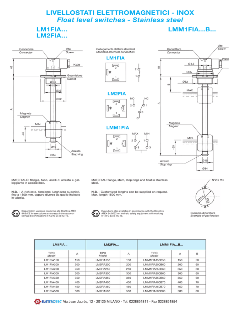
LIVELLOSTATI ELETTROMAGNETICI - INOX
Float level switches - Stainless steel
LM1FIA…
LM2FIA…
LMM1FIA…B...
Vite
Screw
Connettore
Connector
Vite
Screw
Connettore
Connector
Collegamenti elettrici standard
Standard electrical connection
LM1FIA
PG09
Ø4.5
2
40
40
PG09
2
Ø35
Guarnizione
Gasket
1
1
Ø52
B
Ø4.5
MAX.
Ø35
LM2FIA
NO
NC
A
Ø52
2
2
1
A
3
3
1
Magnete
Magnet
C
Magnete
Magnet
MIN.
~35
LMM1FIA
MAX
MIN
2
1
MIN.
2
Ø10
3
1
~35
3
3
Arresto
Stop ring
Ø34
Ø10
Arresto
Stop ring
Ø34
N.B. - A richiesta, forniamo lunghezze superiori,
fino a 1500 mm, oppure diverse da quelle indicate
in tabella.
N.B. - Customized lengths can be supplied on request.
Max. length 1500 mm.
N°2 x M4
Ø
35
.5
MATERIAL: flange, stem, stop rings and float in stainless
steel.
Executions also available in accordance with the Directive
ATEX 94/9/EC on intrinsic safety equipment with marking
II 1/2 G Ex ia IIC T6.
Disponibili in versione conforme alla Direttiva ATEX
94/9/CE in esecuzione a sicurezza intrinseca con
stringa di certificazione II 1/2 G Ex ia IIC T6.
LM1FIA...
LM2FIA...
Esempio di foratura
Exemple of perforation
LMM1FIA...B...
TIPO
Model
A
TIPO
Model
A
TIPO
Model
A
B
LM1FIA150
150
LM2FIA150
150
LMM1FIA150B50
150
50
LM1FIA200
200
LM2FIA200
200
LMM1FIA200B60
200
60
LM1FIA250
250
LM2FIA250
250
LMM1FIA250B60
250
60
LM1FIA300
300
LM2FIA300
300
LMM1FIA300B60
300
60
LM1FIA350
350
LM2FIA350
350
LMM1FIA350B60
350
60
LM1FIA400
400
LM2FIA400
400
LMM1FIA400B70
400
70
LM1FIA450
450
LM2FIA450
450
LMM1FIA450B70
450
70
LM1FIA500
500
LM2FIA500
500
LMM1FIA500B80
500
80
Via Jean Jaurés, 12 - 20125 MILANO - Tel. 0228851811 - Fax 0228851854
Ø43
MATERIALE: flangia, tubo, anelli di arresto e galleggiante in acciaio inox.
LIVELLOSTATI ELETTROMAGNETICI - INOX
Float level switches - Stainless steel
LM1TIA…
LM2TIA…
LMM1TIA…B...
Vite
Screw
PG09
Vite
Screw
Collegamenti elettrici standard
Standard electrical connection
Connettore
Connector
LM1TIA
52
Ch 46
SW 46
2
2
Ch 46
SW 46
Guarnizione
Gasket
1
1
Guarnizione
Gasket
16
16
PG09
52
Connettore
Connector
B
G1 1/4”
LM2TIA
G1 1/4”
NO
2
1
3
3
1
C
MIN.
Magnete
Magnet
~35
LMM1TIA
2
Ø10
MAX
MIN
2
1
MIN.
3
3
1
Ø34
~35
Arresto
Stop ring
A
A
2
Magnete
Magnet
MAX.
NC
3
Ø10
Ø34
Arresto
Stop ring
MATERIALE: flangia filettata G 1 1/4”, tubo, anelli di arresto e galleggiante in
acciaio inox.
MATERIAL: G1 1/4” threaded flange, stem, stop rings and float in stainless
steel.
N.B. - A richiesta, forniamo lunghezze superiori, fino a 1500 mm, oppure diverse da quelle indicate in tabella.
N.B. - Customized lengths can be supplied on request.
Max. length 1500 mm.
Disponibili in versione conforme alla Direttiva ATEX 94/9/CE in esecuzione a sicurezza
intrinseca con stringa di certificazione II 1/2 G Ex ia IIC T6.
LM1TIA...
Executions also available in accordance with the Directive ATEX 94/9/EC on intrinsic
safety equipment with marking II 1/2 G Ex ia IIC T6.
LM2TIA...
LMM1TIA...B...
TIPO
Model
A
TIPO
Model
A
TIPO
Model
A
B
LM1TIA150
150
LM2TIA150
150
LMM1TIA150B50
150
50
LM1TIA200
200
LM2TIA200
200
LMM1TIA200B60
200
60
LM1TIA250
250
LM2TIA250
250
LMM1TIA250B60
250
60
LM1TIA300
300
LM2TIA300
300
LMM1TIA300B60
300
60
LM1TIA350
350
LM2TIA350
350
LMM1TIA350B60
350
60
LM1TIA400
400
LM2TIA400
400
LMM1TIA400B70
400
70
LM1TIA450
450
LM2TIA450
450
LMM1TIA450B70
450
70
LM1TIA500
500
LM2TIA500
500
LMM1TIA500B80
500
80
LIVELLOSTATI ELETTROMAGNETICI - INOX
Float level switches - Stainless steel
LM1PTIA…
LM2PTIA…
PG09
Collegamenti elettrici standard
Standard electrical connection
LM1PTIA
54
Connettore
Connector
Ch 41
SW 41
2
Ch 41
SW 41
1
16
1
B
Guarnizione
Gasket
G1”
LM2PTIA
2
G1”
Guarnizione
Gasket
MAX.
NO
Magnete
Magnet
PG09
Connettore
Connector
2
16
Vite
Screw
54
Vite
Screw
LMM1PTIA…B...
NC
2
1
3
3
1
A
A
C
LMM1PTIA
2
MIN.
MAX
MIN
2
1
MIN.
3
Ø10
3
3
~45
~45
1
Arresto
Stop ring
Ø10
Arresto
Stop ring
Ø29
Ø29
IMPIEGO
Sono stati studiati per controllare il minimo o il massimo livello di
olio, acqua, solventi, in un serbatoio e inviare a distanza un segnale
elettrico. Devono essere montati verticalmente sul coperchio del
serbatoio in modo che il galleggiante disti almeno 50 mm. dalle pareti metalliche.
USE
This series of electromagnetic level switches has been designed
to check the minimum or maximum level of oil, water, solvents in
a tank and send an electric signal to a remote board in case the
fluid goes over or under the set levels. They should be fixed vertically on the cover of the tank, with the float at least 50 mm far
from metal walls.
DATI TECNICI
Potenza commutabile in CC
Potenza commutabile in CA
Intensità di corrente
Tensione max. di lavoro
Tensione di breakdown
Capacità dei contatti aperti
Resistenza d’isolamento
Contatto a riposo (senza fluido)
60 W
60 VA
0.8 A (resistivi)
220 V - 50 Hz
300 V
0,6 pF
1010 Ohm min.
NC
SPECIFICATIONS
Switching capacity in DC
Switching capacity in AC
Current
Voltage
Breakdown voltage
Capacitance
Insulation resistance
Contact (dry condition)
60 W
60 VA
0.8 A (resistive)
220 V - 50 Hz
300 V
0,6 pF
1010 Ohm
NC
CON CONTATTI SPDT
Potenza commutabile
Corrente commutabile
Resistenza d’isolamento
Capacità dei contatti
30 W
0,5 A (resistivi)
109 OHM min.
2 pF
WITH SPDT CONTACTS
Switching capacity
Current
Insulation resistance
Switching capacity
30 W
0.5 A (resistive)
109 Ohm min.
2 pf
Campo di temperatura
Peso specifico liquido
Pressione massima
Viscosità del fluido
Materiale
-10 +80°C
0,8
8 Bar
max 150 cSt
Acciaio inox AISI 316
Temperature range
Fluid specific weight
Maximum pressure
Fluid viscosity
Material
-10 +80°C
0,8
8 Bar
max 150 cSt
Stainless steel AISI 316
PER CARICHI INDUTTIVI IMPIEGARE CIRCUITO DI PROTEZIONE.
WITH INDUCTIVE LOADS A PROTECTION CIRCUIT IS TO BE USED.
Via Jean Jaurés, 12 - 20125 MILANO - Tel. 0228851811 - Fax 0228851854
DATI TECNICI GENERALI
Max viscosità fluido: 150 cSt
Pressione massima: 10 bar
Peso specifico: ≥ 0,7
Connessione elettrica: PG09 – DIN43650
Protezione elettrica: IP65 – DIN40050
Temperatura di lavoro: -10°C…+80°C
Temperatura max con guarnizioni FKM e cavi Silicone: +130°C
GENERAL SPECIFICATIONS
Max. fluid viscosity: 150 cSt
Max. pressure: 10 bar
Fluid specific gravity: ≥ 0.7
Electrical connection: PG09 – DIN43650
Electrical protection: IP65 – DIN40050
Operating temperature: -10°C…+80°C
Max temperature with FKM gasket and Silicone cable: +130°C
DATI ELETTRICI
Le ampolle reed utilizzate nei livellostati ELETTROTEC sono ermeticamente sigillate, ad attuazione magnetica e con una affidabilità
di milioni di cicli.
Il tipo di contatto a riposo è Normalmente Chiuso/Normalmente
Aperto (SPST) o in scambio (SPDT). La portata dei contatti varia
secondo il tipo di ampolla reed adottata. Per i dati elettrici fare riferimento alla tabella sotto riportata.
ELECTRICAL DATA
Standard reed switches in ELETTROTEC level switch units are hermetically-sealed, magnetically actuated, designed for reliability to
millions of cycles.
Switches are Normally Closed/Normally Open (SPST) or SPDT. Each
ELETTROTEC level switch varies in rating depending on the type of
reed switch used, see the chart below for electrical ratings.
Tensione Max
Max Voltage
Potenza Commutabile
Rating Power
Corrente Max
Max Current
Capacità Contatti
Capacitance
Resistenza Isolamento
Insulation Resistance
Contatto (a riposo)
Switch Type (dry)
220V – 50Hz
60 W
60 VA
0.8A
0.6pF
1010 Ohm
NC
220V – 50Hz
60 W
60 VA
0.8A
0.6pF
1010 Ohm
NA/NO
Modelli reversibili
Reversible float
220V – 50Hz
30 W
0.5A
2pF
109 Ohm
NA/NO
Modelli non reversibili
Non-reversible float
220V – 50Hz
30 W
0.5A
2pF
109 Ohm
SPDT
ATTENZIONE: la combinazione tra la tensione e la corrente di
commutazione non deve mai superare la potenza commutabile
indicata in tabella.
WARNING: any combination of the switching voltage and current
must not exceed the given rated power.
I valori elettrici relativi alla portata dei contatti si riferiscono a carichi resistivi. Per applicazioni che implicano carichi induttivi o
capacitivi è richiesto l’impiego di addizionali circuiti protettivi. Per
assicurare lunga durata e ripetibilità dei contatti fare riferimento alle
informazioni tecniche di pagina 6 e 7.
The switch contact ratings, as listed in the switch data chart, are
based on use with resistive type load. For applications requiring the
control of an inductive or capacitance load, additional interface circuitry may be required. To ensure long life and repeatability, see the
contact protection information on pages 6 and 7.
MODEL / MODEL
PUNTI DI INTERVENTO
ACTUATION POINTS
TIPO DI CONTATTO
CONTACT TYPE
LM1…
1 punto di intervento / 1 actuation point
NC
LM1…NA
1 punto di intervento / 1 actuation point
NA / NO
LM2…
1 punto di intervento / 1 actuation point
SPDT
LMM1…
2 punti di intervento - 1 galleggiante
2 actuation points - 1 float
Min. NC
Max. NA / NO
LMM1…
2 punti di intervento – 2 galleggianti
2 actuation points – 2 floats
Min. NC
Max. NC
LM3…
3 punti di intervento – 3 galleggianti
3 actuation points – 3 floats
NC/NC/NC
LM4…
4 punti di intervento – 4 galleggianti
4 actuation points – 4 floats
A richiesta, i modelli LMM1…, LM3…, LM4… sono disponibili con altre combinazioni di contatti.
On request, LMM1… – LM3… – LM4… models can be supplied with different switch operations.
Via Jean Jaurés, 12 - 20125 MILANO - Tel. 0228851811 - Fax 0228851854
NC/NC/NC/NC

