Technical Manual (MTU7391-002-20120402.docx36)
TRANSMITTER 739100 - V / A / ac / dc
FUNZIONI
FUNCTIONS
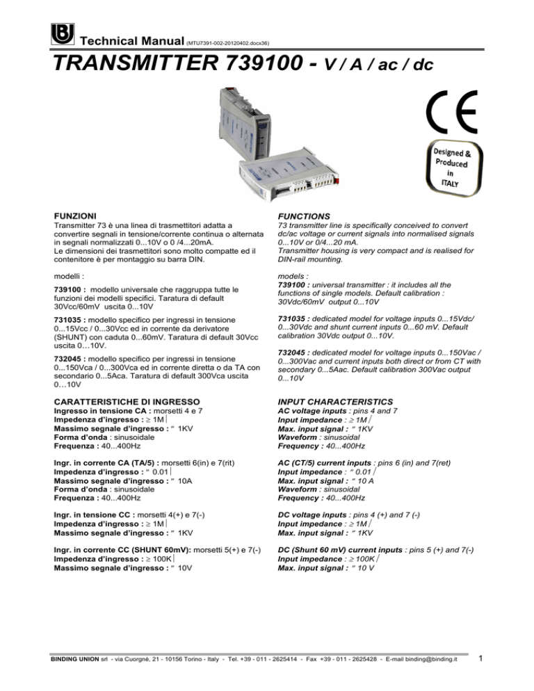
Transmitter 73 è una linea di trasmettitori adatta a
convertire segnali in tensione/corrente continua o alternata
in segnali normalizzati 0...10V o 0 /4...20mA.
Le dimensioni dei trasmettitori sono molto compatte ed il
contenitore è per montaggio su barra DIN.
73 transmitter line is specifically conceived to convert
dc/ac voltage or current signals into normalised signals
0...10V or 0/4...20 mA.
Transmitter housing is very compact and is realised for
DIN-rail mounting.
modelli :
models :
739100 : universal transmitter : it includes all the
functions of single models. Default calibration :
30Vdc/60mV output 0...10V
739100 : modello universale che raggruppa tutte le
funzioni dei modelli specifici. Taratura di default
30Vcc/60mV uscita 0...10V
731035 : modello specifico per ingressi in tensione
0...15Vcc / 0...30Vcc ed in corrente da derivatore
(SHUNT) con caduta 0...60mV. Taratura di default 30Vcc
uscita 0…10V.
732045 : modello specifico per ingressi in tensione
0...150Vca / 0...300Vca ed in corrente diretta o da TA con
secondario 0...5Aca. Taratura di default 300Vca uscita
0…10V
731035 : dedicated model for voltage inputs 0...15Vdc/
0...30Vdc and shunt current inputs 0...60 mV. Default
calibration 30Vdc output 0...10V.
732045 : dedicated model for voltage inputs 0...150Vac /
0...300Vac and current inputs both direct or from CT with
secondary 0...5Aac. Default calibration 300Vac output
0...10V
CARATTERISTICHE DI INGRESSO
INPUT CHARACTERISTICS
Ingresso in tensione CA : morsetti 4 e 7
Impedenza d’ingresso : ≥ 1MΩ
Massimo segnale d’ingresso : ≤ 1KV
Forma d’onda : sinusoidale
Frequenza : 40...400Hz
AC voltage inputs : pins 4 and 7
Input impedance : ≥ 1MΩ
Max. input signal : ≤ 1KV
Waveform : sinusoidal
Frequency : 40...400Hz
Ingr. in corrente CA (TA/5) : morsetti 6(in) e 7(rit)
Impedenza d’ingresso : ≤ 0.01Ω
Massimo segnale d’ingresso : ≤ 10A
Forma d’onda : sinusoidale
Frequenza : 40...400Hz
AC (CT/5) current inputs : pins 6 (in) and 7(ret)
Input impedance : ≤ 0.01Ω
Max. input signal : ≤ 10 A
Waveform : sinusoidal
Frequency : 40...400Hz
Ingr. in tensione CC : morsetti 4(+) e 7(-)
Impedenza d’ingresso : ≥ 1MΩ
Massimo segnale d’ingresso : ≤ 1KV
DC voltage inputs : pins 4 (+) and 7 (-)
Input impedance : ≥ 1MΩ
Max. input signal : ≤ 1KV
Ingr. in corrente CC (SHUNT 60mV): morsetti 5(+) e 7(-)
Impedenza d’ingresso : ≥ 100KΩ
Massimo segnale d’ingresso : ≤ 10V
DC (Shunt 60 mV) current inputs : pins 5 (+) and 7(-)
Input impedance : ≥ 100KΩ
Max. input signal : ≤ 10 V
BINDING UNION srl - via Cuorgnè, 21 - 10156 Torino - Italy - Tel. +39 - 011 - 2625414 - Fax +39 - 011 - 2625428 - E-mail [email protected]
1
Technical Manual (MTU7391-002-20120402.docx36)
TRANSMITTER 7391 - V / A / ac / dc
CARATTERISTICHE DI USCITA
Precisione : ±1% (F.S.) scala singola
Linearità : ≤ 0,25%
Coeff. Di temperatura : ≤ 0,05 % / °C
Tempo di risposta : ≤300ms
Uscita in tensione : 0...10V carico ≥ 100KΩ
Uscita in corrente : 0...20 / 4...20mA carico ≤ 500Ω
CMRR : 86dB tipico.
CARATTERISTICHE GENERALI
Rigidità dielettrica ingresso/uscita : ≥ 2.3kVca 50Hz
Temperatura ambiente : 0 ÷ 50°C
2
Connessioni elettriche : a vite, sez. max 2.5 mm
Installazione : Guida DIN 35 mm
Peso : 150 g
Categoria d’installazione : (cat. di sovratensioni) II°
Grado inquinamento : 2 (CEI EN61010-1)
OUTPUT CHARACTERISTICS
Accuracy : ±1% (F.S.) single range
Linearity : ≤ 0,25%
Temp. Coefficient : ≤ 0,05 % / °C
Response time : ≤300ms
Voltage output : 0...10V load ≥ 100KΩ
Current output : 0...20 / 4...20mA load ≤ 500Ω
CMRR : 86dB typ.
GENERAL CHARACTERISTICS
Input/Output Dielectrical Strength : ≥ 2.3kVac 50 Hz
Ambient temperature : 0÷ 50°C
2
Electrical connection : screw type 2.5mm max.
Mounting : 35mm DIN rail
Weight : 150 g
Installation category : (overvoltage category) II°
Pollution degree : 2
(CEI EN61010-1)
POWER SUPPLY
Alimentazione : 10....30Vcc / Vca
Potenza assorbita : ≤ 2W / 3VA
Corrente di spunto : ≤ 1.5A
Rigidità dielettrica : ≥ 500Vac
Resistenza di isolamento : ≥ 100 MΩ
Power supply : 10...30Vdc / Vac
Power : ≤ 2W / 3VA
Inrush current : ≤ 1.5A
Dielectrical strength : ≥ 500Vac
Isolation resistance : ≥ 100 MΩ
N.B. Lo strumento utilizza alimentatori switching ad alta
frequenza.
Al fine di garantire i livelli di disturbo previsti dalle attuali
norme CE relative alla compatibilità elettromagnetica, si
raccomanda di collegare il morsetto di massa dello
strumento (8) ad una efficace presa di terra. In questo
modo si renderà operativo il filtro EMC presente
all’ingresso dell’alimentatore.
N.B. The instrument is powered by a high frequency
switching power supply.
To guarantee the EMC requirements of European
Standard CE, we recommend to connect the instrument
ground terminal (8) to an effective earth. In this way the
EMC filter at the power supply input will properly work.
DIMENSIONI
DIMENSIONS
120 mm
ALIMENTAZIONE
100 mm
22,5 mm
BINDING UNION srl - via Cuorgnè, 21 - 10156 Torino - Italy - Tel. +39 - 011 - 2625414 - Fax +39 - 011 - 2625428 - E-mail [email protected]
2
Technical Manual (MTU7391-002-20120402.docx36)
TRANSMITTER 7391 - V / A / ac / dc
COLLEGAMENTI ELETTRICI
ELECTRICAL CONNECTIONS
OUTPUT
INPUT
POWER SUPPLY
Power
1 2
S2
3
+
Span
+
-
S1
8 9 10
8
1
Zero
4 5 6 7
(+) L
(-) N
V -
EARTH
SHUNT / 60mV
1
4
TA / 5
PROGRAMMAZIONE INGRESSI
INPUT PROGRAMMING
La programmazione deve essere effettuata senza
alimentazione e segnale d’ingresso.
La configurazione, per il tipo di segnale da convertire, si
effettua sul dip-switch S2, raggiungibile dal lato
connessioni tra i morsetti dell’uscita e dell’ingresso. Vedi
tabella sottostante e programmazione facilitata in ultima
pagina. Le scale sono tutte tarate con apparecchiature
di riferimento.
Il modello 739100 permette la completa programmazione
di tutte le scale indicate, il modello 731035 permette la
programmazione delle scale indicate con sfondo bianco, il
modelo 732045 permette la programmazione delle scale
indicate con sfondo colorato.
This programming must be performed when the device is
not powered and without input signal.
Programming of the signal to be converted can be
performed by means of the dip-switch S 2 that is
accessible on the side where the output and input pins
are located.
See table and simplified programming on pag. 4. All
scales are calibrated with certified device.
The model 739100 can be programmed with any of the
scales indicated in the table below. Model 731035
supports the scales indicated with white background.
Model 732045 supports the scales indicated with a
coloured background.
INPUT
RANGE
AC
DC
0...5A
0...60mV
0...300V
0...150V
0...30V
0...15V
S2
1
ON
OFF
2
OFF
ON
3
4
5
6
7
8
ON
OFF
OFF
OFF
OFF
OFF
OFF
OFF
OFF
ON
OFF
ON
ON
OFF
OFF
OFF
OFF
OFF
OFF
ON
OFF
OFF
OFF
OFF
OFF
OFF
ON
ON
OFF
OFF
OFF
OFF
OFF
OFF
ON
ON
PROGRAMMAZIONE USCITE
OUTPUT PROGRAMMING
La programmazione delle uscite si effettua agendo sul dipswitch S1, posizionato sul frontale del trasmettitore, sotto i
due trimmer. Vedi tabella sottostante. E’ possibile tuttavia
ritoccare la taratura di zero e di span agendo sui trimmer
frontali, dopo aver atteso 10min. dall’accensione.
Output programming can be performed by means of the
dip-switch S 1, located on the front side, below the two
trimmers See table. However, it is possible to trim the
zero and span by the adjusting front trimmers, after
10min. of warm-up time.
S1
OUT
0...10V
0...20mA
4...20mA
1
ON
ON
OFF
I Trasmettitori programmati per segnali in continua e
uscita 0...10V o 0...20mA sono di tipo bipolare, cioè
forniscono un segnale di ±10V o ±20mA proporzionale al
segnale d’ingresso (±15Vcc, ±30Vcc, ±60mV da shunt).
Quando programmati per ingresso in alternata o uscita
4...20mA sono unicamente di tipo unipolare. Vedi funzioni
di trasferimento nella pagina seguente
2
OFF
OFF
ON
3
OFF
ON
ON
4
ON
OFF
OFF
The transmitters programmed for dc input signals and
0...10V or 0...20mA outputs are bipolar types, that is
provide a signal of ±10V or ±20mA proportional to the
input signal of ±15Vcc, ±30Vcc, ±60mV.
When the trasnsmitters are programmed for ac input
signals or 4...20mA output they are unipolar type only.
The following page shows the transfer functions.
BINDING UNION srl - via Cuorgnè, 21 - 10156 Torino - Italy - Tel. +39 - 011 - 2625414 - Fax +39 - 011 - 2625428 - E-mail [email protected]
3
Technical Manual (MTU7391-002-20120402.docx36)
TRANSMITTER 7391 - V / A / ac / dc
FUNZIONI DI TRASFERIMENTO
TRANSFER FUNCTIONS
+Vout
+Iout
+Iout
+20mA
+10V
+20mA
-30V
-15V
-60mV
-30V
-15V
-60mV
+4mA
+60mV
+15V
+30V
-10V
-20mA
-Vout
-Iout
PROGRAMMAZIONE FACILITATA
SIMPLIFIED PROGRAMMING
OUTPUT
INPUT
S1
S2
ON
1
FS ac / dc
+60mV
+15V
+30V
0...15Vdc
0...10V
0...30Vdc
0...60mVdc (shunt)
4
ON
ON
1
ON
1
8
ON
1
8
1
8
0...20mA
4
0...150Vac
ON
ON
4
0...5Aac (TA)
ON
1
4...20mA
0...300Vac
1
8
1
ON
8
1
8
GARANZIA
WARRANTY
Il trasmettitore è garantito da difetti di materiale o di
costruzione rilevati entro un anno dalla data di acquisto.
Un utilizzo improprio del prodotto o una sua
manomissione comportano il decadimento della garanzia.
Post notifica del guasto e accettazione da parte della
Binding Union, l’eventuale strumento da riparare deve
essere inviato in porto franco con le indicazioni del difetto
riscontrato.
The transmitter is guaranteed against material or
construction defects for one year after purchase.
Improper use of the instrument or evident tampering
invalidate the warranty.
Upon failure, after Binding Union has accepted your
request, the equipment should be sent (at your charge)
for repair, with a detailed description of the problem
encountered.
BINDING UNION srl - via Cuorgnè, 21 - 10156 Torino - Italy - Tel. +39 - 011 - 2625414 - Fax +39 - 011 - 2625428 - E-mail [email protected]
4

