Bassa Tensione
Low Voltage
EXVB
Energia e segnalamento
Power and signalling
0,6/1 kV
Riferimento Normativo/Standard Reference
HD 603-5A - NBN C 30-004 (cat. F1) Costruzione e requisiti/Construction and specifications
2014/35/UE
Direttiva Bassa Tensione/Low Voltage Directive
Direttiva RoHS/RoHS Directive
2011/65/CE
BALDASSARI CAVI
EXVB
DESCRIZIONE
DESCRIPTION
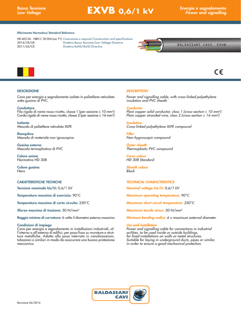
Cavo per energia e segnalamento isolato in polietilene reticolato
sotto guaina di PVC.
Power and signalling cable, with cross-linked polyethylene
insulation and PVC sheath.
Conduttore
Filo rigido di rame rosso ricotto, classe 1 (per sezione ≤ 10 mm2)
Corda rigida di rame rosso ricotto, classe 2 (per sezione ≥ 16 mm2)
Conductor
Plain copper solid conductor, class 1 (cross-section ≤ 10 mm2)
Plain copper stranded wire, class 2 (cross-section ≥ 16 mm2)
Isolante
Mescola di polietilene reticolato XLPE
Insulation
Cross-linked polyethylene XLPE compound
Riempitivo
Mescola di materiale non igroscopico
Filler
Non-hygroscopic compound
Guaina esterna
Mescola termoplastica di PVC
Outer sheath
Thermoplastic PVC compound
Colore anime
Normativa HD 308
Cores colour
HD 308 Standard
Colore guaina
Nero
Sheath colour
Black
CARATTERISTICHE TECNICHE
TECHNICAL CHARACTERISTICS
Tensione nominale Uo/U: 0,6/1 kV
Nominal voltage Uo/U: 0,6/1 kV
Temperatura massima di esercizio: 90°C
Maximum operating temperature: 90°C
Temperatura massima di corto circuito: 250°C
Maximum short circuit temperature: 250°C
Sforzo massimo di trazione: 50 N/mm2
Maximum tensile stress: 50 N/mm2
Raggio minimo di curvatura: 6 volte il diametro esterno massimo
Minimum bending radius: 6 x maximum external diameter
Condizioni di impiego
Cavo per energia e segnalamento in installazioni industriali, all’interno o all’esterno di edifici; per posa fissa su murature o strutture metalliche. Adatto alla posa interrata in canalizzazioni,
tubazioni o similari in modo da assicurare una buona protezione
meccanica.
Use and installation
Power and signalling cable for connections in industrial
acilities, to be used inside or outside buildings,
for fixed installations on walls or metal structures.
Suitable for laying in underground ducts, pipes or similar,
in order to ensure a good mechanical protection.
®
Revisione 06/2016
EXVB
Bassa Tensione
Low Voltage
Energia e segnalamento
Power and signalling
0,6/1 kV
Formazione
Ø
indicativo
conduttore
Spessore
medio
isolante
Spessore
minimo
guaina
Ø
indicativo
produzione
Peso
indicativo
cavo
Resistenza
elettrica
max a 20°C
Portata di corrente
Current rating
Formation
Approx.
conductor
Ø
Average
insulation
thickness
Minimum
sheath
thickness
Approx.
production
Ø
Approx.
cable
weight
Max. electrical
resistance
at 20°C
n° x mm2
mm
mm
mm
mm
kg/km
ohm/ km
A
A
2 x 1,5
1,4
0,7
1,80
10,6
160
12,1
23
30
2 x 2,5
1,8
0,7
1,80
11,4
200
7,41
32
40
2x4
2,2
0,7
1,80
12,3
250
4,61
42
50
65
In aria libera
Free in air
30°C
Interrato
Underground
20°C
2x6
2,8
0,7
1,80
13,4
315
3,08
54
2 x 10
3,6
0,7
1,85
15,1
435
1,83
75
90
2 x 16
4,8
0,7
1,85
18,3
615
1,15
100
120
2 x 25
5,9
0,9
2,00
21,2
930
0,727
127
150
2 x 35
7,0
0,9
2,10
23,5
1195
0,524
157
175
3 x 1,5
1,4
0,7
1,80
11,1
180
12,1
23
30
3 x 2,5
1,8
0,7
1,80
11,9
220
7,41
32
40
3x4
2,2
0,7
1,80
12,9
290
4,61
42
50
65
3x6
2,8
0,7
1,80
14,1
380
3,08
54
3 x 10
3,6
0,7
1,85
15,9
535
1,83
75
90
3 x 16
4,8
0,7
1,95
18,7
770
1,15
100
120
3 x 25
5,9
0,9
2,10
22,6
1170
0,727
127
150
3 x 35
7,0
0,9
2,20
25,1
1515
0,524
157
175
3 x 50
8,2
1,0
2,20
28,5
2025
0,387
192
205
4 x 1,5
1,4
0,7
1,80
11,8
205
12,1
23
30
4 x 2,5
1,8
0,7
1,80
12,7
255
7,41
32
40
4x4
2,2
0,7
1,80
13,8
345
4,61
42
50
65
4x6
2,8
0,7
1,85
15,2
460
3,08
54
4 x 10
3,6
0,7
1,95
17,4
655
1,83
75
90
4 x 16
4,8
0,7
2,00
20,5
960
1,15
100
120
4 x 25
5,9
0,9
2,20
24,8
1450
0,727
127
150
4 x 35
7,0
0,9
2,20
27,3
1885
0,524
157
175
4 x 50
8,2
1,0
2,30
31,3
2550
0,387
192
205
5 x 1,5
1,4
0,7
1,80
12,6
235
12,1
23
30
5 x 2,5
1,8
0,7
1,80
13,6
300
7,41
32
40
5x4
2,2
0,7
1,85
14,9
400
4,61
42
50
65
5x6
2,8
0,7
1,85
16,4
530
3,08
54
5 x 10
3,6
0,7
1,95
18,8
775
1,83
75
90
5 x 16
4,8
0,7
2,10
22,4
1160
1,15
100
120
5 x 25
5,9
0,9
2,20
27,0
1750
0,727
127
150
5 x 35
7,0
0,9
2,20
29,9
2260
0,524
157
175
N.B. Il coefficiente di resistività termica del terreno preso a riferimento per il calcolo della portata dei cavi interrati è di 1 K.m/W, profondità di posa 0,7 m.
Calcolo della portata di corrente eseguito considerando un circuito con 3 conduttori attivi. Per condizioni differenti vedasi la Norma HD 603-5A.
N.B. The thermal resistivity coefficient used as a reference for the calculation of the undergound cables current rating is 1 K.m/W, 0,7 m installation depth.
Calculation of current rating performed considering a circuit with 3 loaded conductors. If conditions are different, see HD 603-5A Standard.
®

