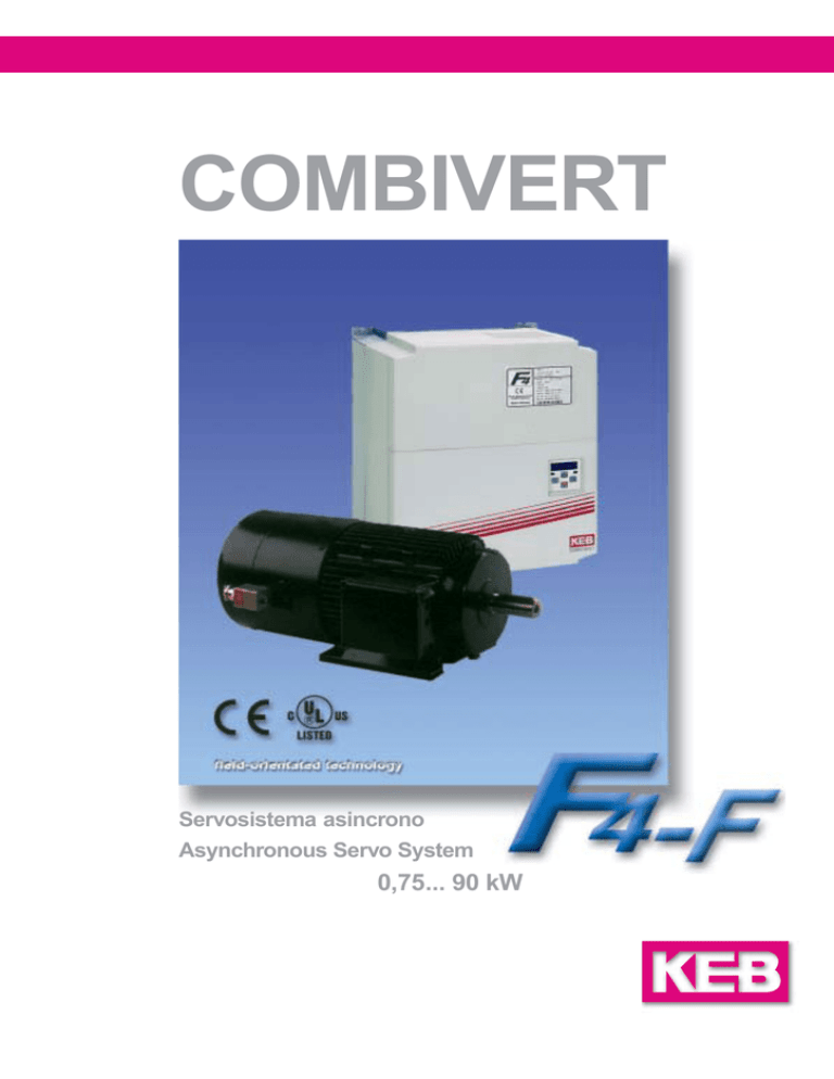
COMBIVERT
Servosistema asincrono
Asynchronous Servo System
0,75... 90 kW
Azionamenti vettoriali ad alte pre- High performance field-orientated
stazioni
drives
Grazie ai KEB COMBIVERT F4F, è ora possibile
utilizzare robusti motori asincroni, che non richiedono manutenzione, in settori applicativi
dove prima era possibile utilizzare o, solo sistemi
in continua oppure servosistemi brushless estremamente costosi.
Utilising the robust, maintenance-free asynchronous motor in combination with COMBIVERT digital drives, it is now possible to incorporate these
drives into fields of application where in the past
service intensive DC or expensive servo technology have been the only options.
in qualità di costruttore di inverter, servosistemi e
motoriduttori, KEB vanta un‘esperienza di 25 anni
che le ha permesso di sviluppare la nuova generazione di inverter vettoriali COMBIVERT F4-F.
As a manufacturer of frequency inverters, servo
systems and geared motors KEB has built up 25
years experience in solving drives applications.
Using this knowledge as a basis, KEB has developed the new generation regulated inverter
series COMBIVERT F4.
KEB COMBIVERT
Il sistema è semplice:
KEB COMBIVERT
Il feedback della velocità del motore è generato da un encoder incrementale o da un trasduttore tipo SIN/COS.
Una rapida regolazione della corrente consente un preciso controllo della coppia e della velocità, per ottenere le massime prestazioni del
motore.
Il cuore del COMBIVERT F4F, è un chip set,
costituito dal KEB7MFC-DSP e dal processore VeCon analogico.
offre i seguenti vantaggi:
The system is easy:
reliable incremental or Sin/Cos encoder feedback gives rotor speed
fast current and speed regulation enables exact control of the rotating field in the motor which
ensures optimum motor performance.
the heart of the COMBIVERT consists of the
chip-set KEB-MFC/DSP and the VeCon analogue processor
and gives the benefits of
Alta risoluzione velocimetrica per applicazioni
su macchine rettificatrici.
meccanica robusta e disponibilità immediata
controllo del tiro per le applicazioni di
avvolgimento
Coppia nominale del motore disponibile fin
da zero giri per ascensori, gru e montacarichi.
Elevata coppia di picco per applicazioni di
alta dinamica (centri di lavoro)
bassa rumorosità, ideale per teatri e
palcoscenici.
2
accurate speed holding for grinding drives
rugged mechanic and around the clock
availability for steel industries
tension control for winding application
rated motor torque at standstill for lifts, cranes
and hoists
high peak torque capacity of acceleration of
tools in machining centres
low noise for theatre and stage
COMBIVERT F4-F
Il principio del controllo vettoriale richiede una
frequente misurazione della tensione, della corrente e della velocità del rotore del motore. Il microprocessore esegue calcoli veloci e li confronta
con il modello matematico del motore. Il processore ricava l‘esatta richiesta di coppia, velocità e
potenza da parte del carico in funzione del quale
stabilisce i parametri ottimali per il pilotaggio del
motore.
Mediante il controllo vettoriale si controlla la corrente attiva del motore e quindi la coppia. Il microprocessore usato
è in grado di eseguire funzioni tipo „PLC“, come, ad esempio, la programmazione di ingressi e di uscite,funzioni di
temporizzazione,ecc., queste
permettono la gestione delle
movimentazioni della macchina anche senza PLC.
Field-orientated technology
has the ability to accurately
control the motor magnetising flux and hence motor
torque. The powerful microprocessor used can also
achieve “PLC” functions,
programmable I/O, timers
etc. thus creating the unique
possibility of networking or
machine control without seperate “PLC”.
Motor
Speed
Torque
Le migliori prestazioni si ottengono quando, in
combinazione con i KEB COMBIVERT F4-F, si
utilizzano i servomotori KEB o i motoriduttori
KEB COMBIGEAR. Questo, spesso, consente di
scendere di una taglia nel dimensionamento del
sistema.
I vantaggi per l‘utente sono
- Investimenti ridotti,
- Rapido ammortamento,
- Tempi di assistenza e
manutenzione ridotti,
- Facile adattamento a
nuove applicazioni,
- Costi di addestramento e
di messa in servizio ridotti
The principle of field-orientated control requires
frequent measurements of voltage, current and
rotor speed. The microprocessor then performs
fast calculations and compares to an adaptive
motor model. This method derives the applications exact torque, speed and power requirements
and therefore provides new regulation values for
the motor, ensuring maximum performance.
Optimum performance is guaranteed when using
the “matched” combination of KEB COMBIVERT
F4-F and eiher KEB servo-motor or KEB COMBIGEAR geared motor. As a result it is often possible to use a drive combination of a smaller kW rating.
M
Mn
The benefits for the user are
- reduced investment,
- quick pay back,
- extended maintenance
and service intervals,
- easy adaption to new requirements,
- low expenditure for training and commissioning.
1,0
300
600
900
1200
1500
Con il controllo vettoriale, le prestazioni del motore, vengono sfruttate completamente consentendo un risparmio di potenza e di costi.
1800
2100
2400
2700
3000
n
min-1
Energy efficient solution as complete drive resources are used reducing power requirement
and running costs.
3
KEB COMBIVERT
KEB COMBIVERT
Il sistema completo di motore asincrono è composto da:
The complete drive system with three-phase a.c.
motors consisting of:
4
Servomotore KEB con encoder line driver
RS 422 - 2500 impulsi/giro;
autoventilato oppure con servoventilazione;
in opzione: freno di sicurezza a molla
nei modelli standard B3, B5, B14 con dimensioni IEC
KEB servo-motor with encoder feedback
RS 422 - 2500 pulses / revolution,
separate ventilation or self-ventilation
Spring-applied brake
option:
Standard design B3, B5, B14 with IEC dimensions
oppure motoriduttore KEB COMBIGEAR nei
modelli:
coassiale ad ingranaggi
ortogonale ad ingranaggi
ad ingranaggi elicoidali
oppure conici
or KEB COMBIGEAR as geared motors in
the design:
inline helical gear,
shaftmounted helical gear,
spur worm gear,
or helical bevel gear
per applicazioni da 0,55 a 75 kW
e velocità in uscita tra 2 e 800 rpm
for applications of 0.55 ... 75 kW
and output speed between 2 ... 800 min-1
Inverter vettoriale ad anello chiuso,
KEB Combivert F4-F con
potenza nominale in uscita da 0,75 a 90 kW
per le funzioni
Regolazione di velocità
Regolazione di coppia
Albero elettrico con rapporto
elettronico
Posizionatore monoasse
exactly matched frequency inverters
KEB Combivert F4-F with
output rating of 0.75 ... 90 kW
for the functions
speed control
torque control
synchronous control as well as
electronic gearbox
and the application software feature
single-axis positioning
per un‘installazione veloce
sono disponibili i cavi per l‘encoder con il connettore già cablato.
for the fast installation
prefabricated encoder cable with plug connection can be supplied
e per una comoda messa in funzione sono disponibili
and for the user friendly commissioning of
systems
- KEB Combivis
- operatori removibili
- KEB LCD terminal
- KEB Combivis
- removable programming operators
- KEB operator terminal
COMBIVERT F4-F
CP. 0
CP. 1
CP. 2
CP. 3
CP. 4
CP. 5
CP. 6
CP. 7
CP. 8
CP. 9
CP. 10
CP. 11
CP. 12
CP. 13
CP. 14
CP. 15
CP. 16
CP. 17
CP. 18
CP. 19
CP. 20
CP. 21
CP. 22
CP. 23
CP. 24
CP. 25
CP. 26
CP. 27
CP. 28
CP. 29
CP. 30
CP. 31
CP. 32
CP. 33
CP. 34
CP. 35
CP. 36
Inserimento password
Velocità attuale
Stato inverter (indicaz. errori etc.)
Corrente apparente del motore (val medio)
Corrente apparente motore (val.di picco)
Coppia attuale
Velocità impostata
Tempo di accelerazione
Tempo di decelerazione
Limite max. coppia
Velocità max. con REF.1=10v
velocità Jog
KP del regolatore di velocità
KI del regolatore di velocità
Impulsi/giro encoder incrementale
Comportamento in caso di errore esterno
REF 1 offset
REF 1-isteresi nel punto di zero
Funzione dell‘uscita A1
Amplificazione dell‘uscita A1
Amplificazione dell‘uscita A2
Condizione di commutazione uscita D1
Condizione di commutazione uscita D2
Livello coppia per l‘uscita D1
Livello velocità per l‘uscita D2
Potenza nominale del motore
Velocità nominale del motore
Corrente nominale del motore
Frequenza nominale del motore
Fattore di potenza del motore cos (ϕ)
Tensione nominale del motore
Acquisizione dati motore (1= on)
Controllo velocità ON/OFF(1= on)
sovralimentazione del motore
Inversione rotazione encoder incrementale 1
Comportamento all‘allarme di fine corsa
funzione dell‘ingresso analogico REF-AUX
quick and easy adjustments using the
CP-Mode with simple parameter structure
Password input
Actual speed indication
Inverter status
Apparent motor current
max. apparent motor current
Actual torque
Set-point speed indication
Acceleration time
Deceleration time
Torque limit
max. set-point speed
Jog speed
P-factor speed regulator
I-factor speed regulator
Incremental encoder pulses / revolution
Behaviour when at external error
Offset REF 1
Zero point hysteresis REF1
Function output A1
Amplification output A1
Amplification output A2
Switching condition output D1
Switching condition output D2
Torque level output D1
Speed level output D2
Motor power
Rated motor speed
Rated motor current
Rated motor frequency
Rated motor output factor cos (ϕ)
Rated motor voltage
Motor adaption
Control on/off
Boost
Rotation reversal incremental encoder 1
Reaction to limit switch
Function 2nd analog input
8 set di parametri nel modo applicativo
consentono flessibilità e adattabilità
8 parameter sets in the application mode
allows flexibility and adaptability
La descrizione dettagliata di tutti i parametri è
nel manuale applicativo
Codice N.: 0F.F4.0EA-K130
described in great detail in the application
manual part no.: 0F.F4.0EA-K130
Function level CP-MODE
Livello funzioni modo CP
Impostazioni facili e rapide con la parametrizzazione semplice nel modo „CP“
5
COMBIVERT F4-F
Power Circuit Specification
Tensione (50/60Hz) 2)
Fasi
-
-
–
EMC
DIM.
16
18
19
20
21
NEW
22
23
NEW
24
_ _ .F4.F1E-3440
-
_ _ . F4.F1G-3440
-
_ _ . F4.F1H-3440
-
_ _ . F4.F1R-3440
_ _ . F4.F3R-3440
_ _ . F4. F1U-3440
-
14.U4.00E-BM01
16.U4.00G-BM01
18.U4.00H-BM01
-
23.U4.0RU-BM00 25.U4.00U-BM00
–
–
–
–
–
–
–
–
–
–
–
–
–
**
trifase
Size
without filter
with internal filter
Part.-No.
mounting filter
[V]
Voltage (50/60Hz) 2)
1 phase
Phases
3 phase
Corrente di uscita
[A]
8,0
6,4
10,5
13,2
18,1
26,5
36,3
46,7
55
66
83
99
127
165
198
[A]
Current
Fusibile di rete
[A]
20
10
20
20
25
35
50
63
80
80
100
160
160
200
315
[A]
Mains fuse
Max. potenza nominale motore 1)[kW]
0,75
2,2
4
5,5
7,5
11
15
18,5
22
30
37
45
55
75
90
[kW]
Max. motor rating 1)
Potenza nominale
[kVA]
1,6
4
6,6
8,3
11
17
23
29
35
42
52
62
80
104
125
[kVA]
Nominal power
Corrente nominale
[A]
4
5,8
9,5
12
16,5
24
33
42
50
60
75
90
110
150
180
[A]
Rated current
Corrente di picco * (30 sec.)
[A]
7,2
10,4
17,1
21,6
29,7
36
49,5
63
75
90
112,5
135
172,5
225
270
[A]
Peak current * (30 sec.)
Tensione
[V]
[V]
Voltage
3 x 0… URETE
3 x 0… UMains
0,5 rpm
0.5 rpm
Speed resolution motor
Immunità
EN 50082 - 2
EN 50082 - 2
Immunity
Emissione interferenze
con filtro EN 50081 -2 ; -1 interferenze condotte
with filter EN 50081 -2 ; -1 line-conducted interferences
Emitted interference
Largh., altezza, prof.
con filtro interno
con filtro esterno
AxBxC
[mm]
90 x 250 x 160
90 x 265 x 210
-
130 x 290 x 200
132 x 352 x 50
170 x 340 x 255
181 x 415 x 56
297 x 340 x 255
300 x 445 x 66
controllo di corrente e tensione di uscita
protezione contro corto circuito tra le fasi e verso terra,
controllo di corrente con sensori di hall
342 x 520 x 360
342 x 520 x 360
340 x 800 x 355
-
-
110 x 478 x 240 110 x 598 x 240
A x B x C Width, height, depth
[mm]
with internal filter
mounting filter
Voltage and current monitoring during dynamic and static
operation, short-circuit proof and earth-fault proof,
hardware current control.
Functions
Circuito freno interno
Braking transistor internal
Sensore PTC interno
PTC evaluation internal
Opzioni
Induttanze di linea, induttanze per motore; resistore freno
Line reactor; motor choke; braking resistor
Options
Temperatura
operativa da -10 a +45°C, di immagazzin. da -25 a +70°C
during operation -10 … +45°C, storage -25 … +70°C
Temperature
Tipo di protezione
IP 20
Potenza motore raccomandata
Servomotore KEB
IP 20
Type of protection
4)
Recommended motor rating 4)
≤ [kW]
Motore standard a 2/4 poli (carico stat.)
200/208/220/230/240 V (180…264V ±0%)
* per basse frequenze di statore < 1sec.
** con filtro interno: Art.-No. F4.F3D-3240
6
15
NEW
NEW
380/400/415/440/460/480 (305…500 ±0%)
monofase
Funzioni
3)
14
3)
[V]
Risoluzione velocità motore
1)
13
NEW
INPUT
con filtro esterno
ENTRATA
12
senza filtro .F4.F1D-3240 .F4.F1D-3440
con filtro interno .F4.F3D-1240 .F4.F3D-3440
Codice N.
USCITA
10
NEW
OUTPUT
Grand.
400 V
17
EMC
230 V
07
DIM.
Dati tecnici del circuito di potenza
2)
0,75
1,5
3
Valore sottolineato = tensione nominale
4)
Carico dinamico
4
5,5
Standard
7,5
Opzione est.
11
15
18,5
1)
3)
22
30
37
45
2/4-pole standard motor (static load)
200/208/220/230/240 V (180…264V ±0%)
55
2)
75
≤ [kW]
underlined value = nominal voltage
4)
KEB servo-motor
Standard
Option external
dynamic load
* for small stator frequencies < 1 sec.
7
Collegamento
Connection
1
Presa Sub-D a 9 poli, interfaccia parametrizzazione
9-pole Sub-D socket, parameterizing interface
1
1
TR
IEB
ST
EC
HN
6
2
I
7
8
4
9 1
0
20
11
12
13
14
15
16
17
21
18
INP
VO UT
CY LTA
CLE GE
OU
XX
PO TPU
XX XXXX
VOL WE T
XX
TAG R
XX XXXX
AC
E
XX
XX
VE -MO
XX XX
XX X
AR R-N T.
X
XX XX XX
SE T-N O.
4,0 XX XX XX
R-N O.
XX KW XXXX XXXX XXXX
O.
XX XX
,
950 .F4 XXXX2/4 P, XXXX
000 .XXX-X XX 50/
01/
XX 60
XX XXX XX HZ
XX
X˜
XX
X
22
Morsettiera X2, connessione morsetti di controllo
Terminal strip X2, connection of the control terminals
23
19
CU
RR
EN
T
KE
D-3Karl E.B Ant
267 Brinrieb
7 Bar kmaste
Ma
chn
de
in Ge ntrupnn Gmik
bH
rma
ny
3
.
C
N
FU D
EE
SP
P
O
ST
5
AN
2
T
AR
ST
R
TE
EN R
F/
elec
tron
ic
2
3
Connettore faston, connessione schermo/messa a terra
AMP tab connector, shield connection / earthing
4
Presa Sub-D a 9 poli X5, entrata encoder incrementale 2
9-pole Sub-D-socket X5, incremental encoder input 2
5
Presa Sub-D a 15 poli X4 entrata encoder incrementale 1
15-pole Sub-D-socket X4 incremental encoder input 1
3
4
5
L1
L2
L3
6
7
L1
L2
L3
PA
6
PB
U
V
8
9
10
1
2
9
8
12
10
3
7
6
11
4
7
Morsetti OH / OH, collegamento PTC motore
Terminals OH / OH, PTC-connection
8
Collegamento PE
9
Scatola morsetti: collegamento tensione motore, PTC, freno (opzionale)
Terminal box: connection motor voltage, PTC, brake (option)
PE connection
5
U1
V1
W1
2
10
1 9 8
10 12 7
3
Connettore 12 poli encoder SIN/COS oppure encoder incrementale
12-pole encoder plug connection SIN/COS- or incremental encoder
6
4
11
5
Morsetti circuito di controllo X2
Control Circuit Terminals X2
1
Abilitazione inverter
Control release
13
Com. per in/out analogici
Common
2
Reset errori
Reset
14
Riferimento analogico +
Analog. set value +
3
Nel modo CP senza funzione CP-Mode without func.
15
Riferimento analogico -
Analog. set value -
4
Nel modo CP senza funzione CP-Mode without func.
16
Riferimento ausiliario +
Progr. analog input +
5
Velocità Jog avanti
Jog-speed forward
17
Riferimento ausiliario -
Progr. analog input -
6
Velocità Jog indietro
Jog-speed reverse
18
Usc. analog. programm. A 1
Progr. analog out 1
7
Ingresso errore esterno
Input ext. fault
19
Usc. analog. programm. A 2
Analog out speed
8
Uscita digitale D1
Digital output 1
20
Contatto N.O.
N.O. contact
9
}
Uscita digitale D2
Digital output 2
21
Contatto N.C
10
Uscita tensione + 18V
+ 18V voltage output
22
Comune Relé
11
Comune per in/out digitali
Digital ground
23
Tensione di aliment. est.
12
Tensione di rif. + 10 V
+ 10V ref. voltage
Relé
N.C. contact
Switching contact
}
Relay
Ext. supply + 24V
Morsetti del circuito di potenza
Power Circuit Terminals
Circuito di potenza-grandezza 07 (1/3 x 230V) e 10 (3 x 400V)
Collegamento monofase: L1/L2
Power circuit size 07 (1/3 x 230V) and size 10 (3 x 400V)
single phase connection: L1/L2
L1
L2
L3
PA PB
U
Circuito di potenza-grandezza12-24 (3 x 400V)
L1
8
Morsettiera, collegamento motore, collegamenti rete, resistore freno
Terminal strip, connection motor, mains connection, braking resistor
W
L2
L3
-
V
W
OH OH
Power circuit for size 12-24 (3 x 400V)
PA+ PB
U
V
W
OH OH
COMBIVERT F4-F
Dati tecnici motore (4 poli, 50 Hz)
Codice N.
Part.-No.
Grand.
Size
Motor Specification (4-pole, 50 Hz)
IK/IN
cos ϕ
Inerzia
Inertia
[kgm2]
2,3
2,3
2,7
3,3
0,72
0,73
0,00087
0,00107
4
Potenza
Power
[kW]
Tensione
Voltage
[V]
nN
Coppia nom. Corr. nom.
MK/MN
Rated torque Rated current
[rpm]
[Nm]
[A]
2,78
3,63
1,6
2,10
Freno 2)
Brake
[Nm]
08.E8.6_1-26_1
08.E8.6_3-26_1
80
0,55
0,75
230/400
230/400
1400
1400
3,75
5,12
09.E8.6_1-26_1
09.E8.6_3-26_1
90
1,1
1,5
400
400
1410
1400
7,45
10,2
2,62
3,4
2,5
2,6
3,4
3,4
0,81
0,83
0,00207
0,0026
8
10.E8.6_3-26_1
10.E8.6_5-26_1
100
2,2
3,0
400
400
1420
1435
14,2
20,0
5,15
6,7
3,1
2,8
4,3
3,8
0,78
0,79
0,0040
0,00725
16
32
11.E8.6_2-26_1
13.E8.6_1-26_1
112
132
4,0
5,5
400
400
1435
1440
26,6
36,5
8,80
10,5
3,2
3,2
4,8
4,1
0,78
0,89
0,0090
0,0150
32
60
13.E8.6_2-26_1
16.E8.6_2-26_1
160
7,5
11,0
400
400
1440
1440
49,7
73,0
15,0
21,5
2,4
2,4
3,7
4,4
0,84
0,85
0,0280
0,0350
100
100
16.E8.6_3-26_1
18.E8.6_2-26_1
180
15,0
18,5
400
400
1455
1455
98,5
121
28,5
35,0
2,5
2,5
4,4
4,1
0,86
0,86
0,0780
0,0900
150
150
18.E8.6_3-26_1
20.E8.6_3-26_1
200
22,0
30,0
400
400
1470
1465
143
195
42,0
55,5
2,6
2,5
3,6
4,0
0,84
0,85
0,1380
0,1680
250
250
1)
22.E8.6_1-26_1
22.E8.6_2-26_1
225
37,0
45,0
400
400
1470
1470
240
292
67,0
81,0
2,5
2,5
3,9
3,6
0,86
0,86
0,2750
0,3130
25.E8.6_2-26_1
28.E8.6_1-26_1
250
280
55,0
75,0
400
400
1475
1480
356
484
98,5
134,0
2,3
2,2
3,5
2,9
0,86
0,86
0,5250
0,9500
1)
Su richiesta
2)
1)
Opzione
upon request
2)
1)
1)
Option
Dati tecnici dell‘encoder incrementale
Incremental Encoder Specification
RS422, tensione di alimentazione 5V (± 5%)
traccia A, B e 0, 2500 I/giro; max. 200 kHz
Cod. N.: 00.EK.QI1-0503 Encoder
Cod. N.: 00.EK.QIZ-0001 Connettore encoder
RS422, voltage supply 5V (± 5%)
A, B and 0-track, 2500 I/revolution; max. 200 kHz
Part.No.: 00.EK.QI1-0503 Encoder
Part.No.: 00.EK.QIZ-0001 Encoder connector
Set cavo encoder
Encoder Cable Set
Lungh.
Cod. N.
5m
00.F4.109-0005
10 m
00.F4.109-0010
Connettore Encoder / Lato motore
15 m
00.F4.109-0015
20 m
00.F4.109-0020
30 m
00.F4.109-0030
Length
Part.-No.
Plug encoder / motor side
Tipo: CONINVERS Serie RC, modello Q
Contatto ad innesto RC-12 Pin BA
(12 poli con contatti a crimpare)
Type: CONINVERS Series RC, design Q
Plug-in contact design RC-12 Pin BA
(Shift, Crimp 12-pole)
Connettore lato inverter
Plug frequency inverter side (Driver)
Connettore sub D 15 poli femmina (HD)
Plug-in contact design D-Sub 15-pole female (HD)
9
F4 – un convertitore dalle mille combinazioni
F4 – an inverter with many possibilities
Apparecchiatura pre-programmata
con indicatore a LED operativo e di
errore
Preadjusted basic unit in a control cabinet
with cover status display and fault
indicator.
Programmazione e visualizzazione
con l’OPERATORE DIGITALE
00.F4.010-2009
Operation and indication by means of the
DIGITAL OPERATOR
00.F4.010-2009
L’aggiunta di un’interfaccia seriale
isolata RS232/485 e di un connettore
sub-min D consente di ottenere un
OPERATORE CON INTERFACCIA
SERIALE
00.F4.010-1009
Additionally with isolated serial
RS232/485 interface on Sub-min Dconnector with the
INTERFACE OPERATOR
00.F4.010-1009
L’operatore base e la stazione di
programmazione
MEMORY OPERATOR
00.F4.010-3009
cosentono un semplice upload e
download dei parametri da un
inverter all’altro.
- Con il COMBICARD-System
00.F4.000-3009
la programmazione dell’inverter
può essere conservata in un
archivio sicuro.
E’ possiibile garantire la comunicazione field bus con un PC o
un PLC grazie ai moduli di interfaccia seriale intercambiabili.
Operatore-CAN
00.F4.010-5009
Basic operator and programming
station
MEMORY OPERATOR
00.F4.010-3009
plugable, universal data medium for
easy to service customer
settings
- in connection with the
COMBICARD SYSTEM
00.F4.000-3009
a safe tool for the unit
parameterizing.
Field bus communication in interconnection with PLC or PC
is done via pluggable serial interface modules.
Operatore per fibre ottiche
Fiber optic operator
00.F4.010-A009
Operatore-LON
00.F4.010-4009
Operatore BUS
00.F4.010-7009
Operatore InterBus-Loop
00.F4.010-8009
Operatore Profibus
00.F4.010-6018
10
COMBIVERT F4-F
Sistemi KEB per l’automazione
KEB Drive Systems
COMBIVIS
11
© KEB 00.00.000-3F4F 03/2000
KEB ITALIA s.r.l.
Via Newton, 2
20019 Settimo Milanese (Milano)
Tel. 02/33500782 - 33500814 (ric. aut.)
Telefax 02/33500790
Internet: www.keb.it • E-mail: [email protected]

