Idea
16455
16456
16455 Unità elettronica di chiamata - 3 moduli
16456 Unità elettronica di risposta, alimentazione 12 V~ ±10% 50-60 Hz o 12 V d.c. ±10% (SELV) - 3 moduli
16455 External electronic ringing unit - 3 modules
16455 Unité électronique d’appel - 3 modules
16456 Internal electronic reply unit, supply 12 V~ 16456 Unité électronique de réponse, ±10% 50-60 Hz or 12 V d.c. ±10%
alimentation 12 V~ ±10% 50-60 Hz ou 12 V d.c.
(SELV) - 3 modules
±10% (TBTS) - 3 modules
Campo d’applicazione
Scope
Domain d’application
Le unità di chiamata e di risposta componenti il sistema per richiesta d’udienza permettono di governare l’accesso in ambienti riservati (es. uffici
manageriali, ambulatori, ecc.)
The external ringing unit and the internal reply unit forming the admittance request system allow the access
control to restricted environments, i.e. executive offices,
surgeries, etc
Les unités d’appel et de réponse qui forment le système de demande d’audience permettent le contrôle
de l’accès dans locaux réservés (bureaux directifs, dispensaires, etc.)
Principali caratteristiche
Technical specifications
Caractéristiques principales
•involucro in policarbonato autoestinguente
•tensione di alimentazione: 12 V~ ±10% 50-60 Hz o
12 V d.c. ±10% (SELV). I morsetti di alimentazione
sono presenti sull’unità di risposta; l’unità di chiamata viene alimentata attraverso i collegamenti
con l’unità di risposta
•assorbimento massimo: 300 mA con segnalazioni
ottiche ed acustiche attivate
•possibilità di collegare fino a due unità esterne di chiamata e due unità di risposta per un massimo di quattro apparecchi che funzionino contemporaneamente
•grado di protezione IP41 con apparecchio installato
ad incasso in pareti verticali lisce con relativo supporto, placca ed eventuali copriforo
•l’apparecchio va utilizzato in luoghi asciutti e non
polverosi ad una temperatura compresa tra 0 °C e
+40 °C
•enclosure: polycarbonate resistant to abnormal heat
and to fire
•supply voltage: 12 V~ ±10% 50-60 Hz or 12 V d.c.
±10% (SELV). The terminals for the supply are located on the reply unit; the ringing unit is supplied
through the connection with the reply unit
•absorption: 300 mA max with activated optical and
acoustic signals
•possibility of connecting up to 2 external ringing
units and 2 internal reply units (4 equipments) operating simultaneously
•protection degree IP41 with equipment flush installed
on smooth vertical walls with the relevant supporting
frame, cover plate and possible blank covers
•the equipment must be used in dry, undusty locations,
at a room temperature between 0 °C and +40 °C
Installazione
•to be supplied through security isolating transformer
•for the wiring, use conduits segregated from the 230
V~ mains
•use supply conductors with cross-sectional area ≥ 0.5
mm2
•the wiring length between ringing unit and reply unit
must not exceed 50 m
•it can be mounted on table type slanting mounting
boxes 16803 and 16806
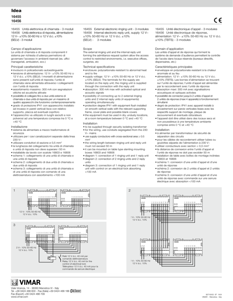
•diagram 1: connection of 1 ringing unit and 1 reply unit
•diagram 2: connection of 2 ringing units and 2 reply
units
•diagram 3: connection of 1 ringing unit and 1 reply
unit with control on an electrical lock absorbing
<100 mA
•enveloppe en polycarbonate resistant à la chaleur
anormale et au feu
•alimentation: 12 V~ ±10% 50-60 Hz ou 12 V d.c.
±10% (TBTS). Les bornes d’alimentation se trouvent
sur l’unité de réponse; l’unité d’appel est alimentée
par le raccordement avec l’unité de réponse
•absorption maxi: 300 mA avec signalisations
acoustiques et optiques activées
•possibilité de connecter jusqu’à 2 unités d’appel et 2 unités de réponse (maxi 4 appareils) à fonctionnement
simultané
•degré de protection: IP41 avec appareil installé à
encastrement sur parois verticales lisses avec les respectifs support de montage, plaque de recouvrement et eventuels obturateurs
•l’appareil doit être utilisé dans des locaux secs et
non poussiéreux à une température ambiante comprise entre 0 °C et +40 °C
•sistema da alimentare a mezzo trasformatore di
sicurezza
•utilizzare per i cavi canalizzazioni separate dalla linea
230 V~
•utilizzare conduttori di sezione ø 0,5 mm2
•la lunghezza del collegamento tra unità di chiamata
e unità di risposta non deve superare i 50 m
•installabile da tavolo con scatole 16803 e 16806
•schema 1: collegamento di una unità di chiamata e
una unità di risposta
•schema 2: collegamento di due unità di chiamata e
due unità di risposta
•schema 3: collegamento di una unità di chiamata e
di una unità di risposta con comando di una elettroserratura con assorbimento <100 mA
1
16456
L1 L2
Installation
•à alimenter par transformateur de sécurité de séparation des circuits
•pour les câbles de raccordement utiliser tubes ou
goulottes séparés de l’alimentation à 230 V~
•utiliser conducteurs avec section ≥ 0,5 mm2
•la distance de connexion entre l’unité d’appel et l’unité de réponse ne doit pas excéder 50 m
•installation de table avec boîtes de montage inclinées
16803 et 16806
•schéma 1: connexion d’une unité d’appel et d’une
unité de réponse
•schéma 2: connexion de 2 unités d’appel et 2 unités
de réponse
•schéma 3: connexion d’une unité d’appel et d’une
unité de réponse avec commande sur une serrure
électrique avec absorption <100 mA
2
16455
1 2 3 4 5 6 7 8 9
Installation
1 2 3 4 5 6
16456
L1 L2
16455
1 2 3 4 5 6 7 8 9
1 2 3 4 5 6
12 V~ 10% 50-60 Hz
12 V d.c. 10%
12 V~ 10% 50-60 Hz
12 V d.c. 10%
3
16456
L1 L2
16455
1 2 3 4 5 6 7 8 9
1 2 3 4 5 6
16456
L1 L2
12 V~ 10% 50-60 Hz
12 V d.c. 10%
Relé 12 V d.c. 40 mA per
comando elettroserratura
Relay 12 V d.c. 40 mA for the
control of electrical lock
Télérupteur 12 V d.c. 40 mA pour la
commande de serrure électrique
Viale Vicenza, 14 - 36063 Marostica VI - Italy
Tel. +39 0424 488 600 - Fax (Italia) +39 0424 488 188
Fax (Export) +39 0424 488 709
www.vimar.com
16455
1 2 3 4 5 6 7 8 9
1 2 3 4 5 6
12 V~ 10% 50-60 Hz
12 V d.c. 10%
90716455 0F 1404
VIMAR - Marostica - Italy
Funzionamento
Operation
Fonctionnement
16455
16456
Segnalazioni ottiche
Optical signals
Signalisations optiques
Segnalazione acustica
della condizione "avanti"
Acoustic signal of the
"come in" conditon
Signalisation acoustique
de la condition "entrez"
Avanti
Attendere
Pulsante di chiamata
Ringing pushbutton
Poussoir d'appel
Occupato
Targhetta portanome
Name-plate
Porte-étiquette
16455
Segnalazioni ottiche
Reply optical signals
Signalisations optiques
Segnalazione ottica
di chiamata
Optical signal of
occurred ringing
Signalisation optique
d'appel
Avanti
Segnalazione acustica
Acoustic signal
Signalisation acoustique
Attendere
Occupato
Pulsanti di risposta
Operation pushbuttons
Poussoirs de réponse
16456
Pulsante
Led verde
"AVANTI"
Pushbutton
Poussoir
Led giallo
Led rosso
"ATTENDERE" "OCCUPATO"
Green led
"COME IN"
Yellow led
"WAIT"
Red led
"ENGAGED"
Led verte
"ENTREZ"
Led jaune
"ATTENDEZ"
Led rouge
"OCCUPE"
Suoneria
Bell
Sonnerie
Pulsante
"AVANTI"
Pulsante
Led verde
Led giallo
Led rosso
Pulsante
"ATTENDERE" "OCCUPATO" "AVANTI" "ATTENDERE" "OCCUPATO"
Pushbutton
"COME IN"
Pushbutton
"WAIT"
Poussoir
"ENTREZ"
Poussoir
"ATTENDEZ"
Pushbutton Green led
"ENGAGED" "COME IN"
Poussoir
"OCCUPE"
Yellow led
Red led
"WAIT"
"ENGAGED"
Led verte
Led jaune
Led rouge
"ENTREZ" "ATTENDEZ" "OCCUPE"
Suoneria
Bell
Sonnerie
Led
"CHIAMATA"
Led
"RINGING"
Led
"APPEL"
Legenda
Legend
Légende
Pulsante premuto - Pushbutton pressed - Poussoir appuyé
Pulsante non attivo - Pushbutton deactivated - Poussoir déactivé
Led acceso - Led on - Led allumée
Led lampeggiante - Led blinking - Led clignotante
Segnalazione acustica - Acoustic signal - Signalisation acoustique
Regole d’installazione
Installation rules
Règles d’installation
•l’installazione deve essere effettuata in conformità
alle norme CEI vigenti
•prima di operare sull’impianto togliere tensione
agendo sull’interruttore generale
•utilizzare conduttori isolati di colore giallo/verde solo
per il collegamento di terra
•verificare che la sezione dei conduttori di alimentazione sia adeguata al carico alimentato ed
in ogni caso non inferiore a 1,5 mm2
•serrare accuratamente i conduttori nei morsetti, in
quanto serraggi imperfetti possono provocare surriscaldamenti fino a temperature sufficienti ad
innescare un incendio
•the installation must be done according to in force
Italian CEI specifications (or equivalent rules for electrical installations of buildings)
•disconnect the mains acting on the main switch
before operating on the system
•use the yellow/green insulated conductors only for
the connection to the earthing circuit
•verify if the supply conductors cross-sectional area
is sufficient for the feeded load, in any case it shall
never be less than 1.5 mm2
•clamp fully, with care, the conductors in the terminals;
faulty clampings can cause temperature rises high
enough for a fire risk
•l’installation doit être effectuée selon les normes italiennes CEI en vigueur (ou normes équivalentes
pour les installations électriques des bâtiments)
•couper l’alimentation en agissant sur l’interrupteur
général avant d’intervenir sur l’installation
•utiliser les câbles isolés de couleur jaune/verte seulement pour la connexion au circuit de terre
•vérifier si la section des conducteurs d’alimentation
est suffisante pour la charge alimentée, elle ne doit
quand même jamais être inférieure à 1,5 mm2
•serrer les conducteurs dans les bornes avec soin;
un mauvais serrage peut provoquer un échauffement excessif avec risque d’incendie

