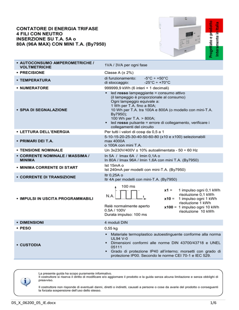
Progettato e prodotto
Interamente in Italia
CONTATORE DI ENERGIA TRIFASE
4 FILI CON NEUTRO
INSERZIONE SU T.A. 5A o
80A (96A MAX) CON MINI T.A. (By7950)
AUTOCONSUMO AMPEROMETRICHE /
VOLTMETRICHE
1VA / 3VA per ogni fase
PRECISIONE
Classe A (± 2%)
TEMPERATURA
di funzionamento:
di stoccaggio:
NUMERATORE
999999,9 kWh (6 interi + 1 decimali)
led rosso lampeggiante = consumo attivo
(il lampeggio é proporzionale al consumo)
Ogni lampeggio equivale a:
1 Wh per T.A. fino a 80A;
10 Wh per T.A. tra 100A e 800A (o modello con mini-T.A.
By7950);
100 Wh per T.A. > 800A;
led rosso pulsante = errore di collegamento, verificare i
collegamenti del circuito
Per tutti i valori di cosφ da 0,5 a 1
5-10-15-20-25-30-40-50-60-80 (x10 e x100) selezionabili
max 4000A
o 100A con mini T.A.
Un 3x230V/400V ± 10% autoalimentata - 50 ÷ 60 Hz
SPIA DI SEGNALAZIONE
LETTURA DELL’ENERGIA
PRIMARI DEI T.A.
TENSIONE NOMINALE
CORRENTE NOMINALE / MASSIMA /
MINIMA
MINIMA CORRENTE DI START
CORRENTE DI TRANSIZIONE
-5°C ÷ +50°C
-25°C ÷ +70°C
In 5A / Imax 6A / Imin 0,1A o
In 80A / Imax 96A / Imin 1,6A con mini T.A. (By7950)
Ist 15mA o
Ist 240mA per modelli con mini-T.A. (By7950)
Itr 0,25A o
Itr 4A per modelli con mini-T.A. (By7950)
x1 =
IMPULSI IN USCITA PROGRAMMABILI
Relé normalmente aperto
0.5A / 100V
Durata impulso: 100 ms
1 impulso ogni 0,1 kWh
risoluzione 0,1 kWh
x10 = 1 impulso ogni 1 kWh
risoluzione 1 kWh
x100 = 1 impulso ogni 10 kWh
risoluzione 10 kWh
DIMENSIONI
4 moduli DIN
PESO
0,55 kg
CUSTODIA
Materiale termoplastico autoestinguente conforme alla norma
UL94 V-0
Dimensioni conformi alle norme DIN 43700/43718 e UNEL
05111
Grado di protezione IP40 all’interno; morsetti con grado di
protezione IP00. Secondo le norme CEI 70-1 e IEC 529.
La presente guida ha scopo puramente informativo.
Il costruttore si riserva il diritto di modificare e/o aggiornare il prodotto e la guida senza alcuna limitazione e senza obblighi di
preavviso.
Il costruttore non risponde di eventuali danni, diretti o indiretti, causati a persone o cose da avarie del prodotto o conseguenti
la forzata sospensione dell’uso dello stesso.
DS_X_06200_05_IE.docx
1/6
COLLEGAMENTI E TEST AUTOMATICO
1. Scegliere il rapporto del TA e l’impulso in uscita selezionando i minidip appropriati. Non necessario nel modello
con mini-T.A. (By7950)
2. Collegare i circuiti di corrente e tensione come da schema
3. Dare alimentazione ed attendere almeno 3 secondi: in assenza di carico 3 led rossi accesi, verde lampeggiante,
led rosso sul fronte spento.
4. Verificare che il led rosso frontale lampeggi con carico a conferma del corretto collegamento.
a. Attraverso lo sportellino superiore si noterà che il led verde (A) è acceso e che i led rossi (B corrispondente
1
alla fase L1, C corrispondente alla fase L2 e D corrispondente alla fase L3) sono spenti.
b. Se invece il led rosso frontale pulsa (la sua luminosità si alza e si abbassa gradualmente), significa che c’è
una anomalia nel collegamento. In questo caso sullo strumento si noterà che il led verde (A) è spento ed
uno, due o tutti e tre i led rossi (B, C e D) corrispondenti alla fase collegata erroneamente sono accesi. In
questo caso verificare nuovamente i collegamenti. Potrebbero essersi verificate le seguenti anomalie:
i. La corrente in un circuito di misura amperometrica circola in modo contrario per errori di collegamento
dei T.A. (la corrente deve entrare dal lato P1 ed uscire dal lato P2)
ii. E’ stato invertito il collegamento tra i tre T.A. e le rispettive fasi (Esempio: T.A. su L1 invece che su L3
etc.)
iii. Manca un collegamento nel circuito di misura voltmetrico della fase corrispondente al led rosso acceso
NOTA
Nel caso mancasse la fase L1 o
la fase L3, il contatore non
funzionerà in quanto non più
alimentato.
1
Il led verde si accenderà a luce fissa dopo che il contatore ha verificato un consumo iniziale di energia su tutte e tre le
fasi (L1, l2, L3). Lo scopo è quello di segnalare il regolare funzionamento dopo l’installazione dove sicuramente
sono presenti le tensioni ma non necessariamente un consumo di corrente
DS_X_06200_05_IE.docx
2/6
DS_X_06200_05_IE.docx
3/6
DS_X_06200_05_IE.docx
4/6
Designed and
manufactured entirely
in Italy
THREEPHASE ENERGY METER
4 WIRES WITH NEUTRAL
INSERTION ON C.T. 5A or
80A (96A MAX) WITH MINI-C.T. (By7950)
AMPEROMETRIC / VOLTMETRIC
SELFCONSUMPTION
1VA / 3VA for each phase
PRECISION
Class A
TEMPERATURE
working:
storage:
DISPLAY
999999.9 kWh (6 integer + 1 decimals)
Flashing red led = active consumption
(the flashing is proportional to the consumption)
Each flashing is equal to:
1 Wh for C.T. up to 80A;
10 Wh for C.T. ratio between 100A and 800A (or model with
mini-C.T. By7950);
100 Wh for C.T. ratio > 800A;
Pulse red led = connection error, it is necessary to verify the
connections of the circuit
For every cosφ value from 0.5 to 1
5-10-15-20-25-30-40-50-60-80 (x10 e x100) selectables
max 4000A
o 100A with mini C.T.
Un 3x230V/400V ± 10% self powered - 50 ÷ 60 Hz
WARNING LIGHT
ENERGY DATA
C.T. PRIMARIES
NOMINAL VOLTAGE
NOMINAL / MAXIMUM / MINIMUM
CURRENT
MINIMUM START CURRENT
TRANSITION CURRENT
-5°C ÷ +50°C
-25°C ÷ +70°C
In 5A / Imax 6A / Imin 0.1A or
In 80A / Imax 96A / Imin 1,6A with mini C.T. (By7950)
Ist 15mA or
Ist 240mA for models with mini-C.T. (By7950)
Itr 0,25A or
Itr 4A for models with mini-C.T. (By7950)
x1 =
PROGRAMMABLE OUTPUT PULSES
Normally open relay
0.5A / 100V
Pulse duration: 100 ms
1 pulse every 0,1 kWh
accuracy 0,1 kWh
x10 = 1 pulse every 1 kWh
accuracy 1 kWh
x100 = 1 pulse every 10 kWh
accuracy 10 kWh
DIMENSIONS
4 DIN modules
WEIGHT
0,55 kg
HOUSING
Self-extinguishing thermoplastic material according to the
UL94 V-0 standard
Dimensions according to DIN 43700/43718 and UNEL 05111
standards
IP40 protection degree inside the device; terminals with IP00
protection degree. According to CEI 70-1 and IEC 529
standards.
This guide is for information only.
The manufacturer reserves the right to modify and / or update the product manual without reservation and without prior notice.
The manufacturer, including his international representatives or agents, do not accept any liability for any incidental damage,
directly or indirectly, to people or properties through the use of his products.
DS_X_06200_05_IE.docx
5/6
CONNECTIONS AND AUTOMATIC TEST
1. Choose the C.T. ratio and the output pulse by selecting the appropriate minidip. You needn’t to do it in case of
mini T.A. (By7950) model.
2. Connect current and voltage circuits as shown in the diagram.
3. Power and wait for at least 3 seconds: if there is no load the 3 red leds are switched on, the green led is flashing
and the frontal red led is switched off.
4. Verify that the red frontal led flashes when there is load to confirm the correct connection.
a. See the upper small panel: it can be noted that the green led (A) is switched on and the red leds (B
corresponding to phase L1, C corresponding to phase L2 and D corresponding to phase L3) are switched
2
off.
b. Whereas, if the frontal red led throbs (the brightness gradually increases and decreases), it means there is
an anomaly in the connection. In this case on the top of the instrument, it will be noted that the green led
(A) is switched off and one, two or all three red leds (B, C and D) corresponding to the phase incorrectly
connected, are switched on. In this case verify that the connections again. The following anomalies may
have verified:
i. the current in an amperometric measuring circuit circulates in reverse mode due to errors in the C.T.
connection (the current must enter from the P1 side and exit from the P2 side)
ii. the connection between the three C.T. and the respective phases has been reverser (Example: C.T. on
L1 instead of on L3 etc.)
iii. a connection in the voltmetric measuring circuit of the phase corresponding to the red switched on led is
missing
NOTE
In case of no L1 or L3 phase, the
meter will not work as it would be
no longer powered.
2
The green led will light on with a steady light after the meter learned a starting energy consumption on all the 3
phases (L1, L2, L3). The reason is to report the right working after the installation when voltages are present but the
current cunsumption may be absent.
DS_X_06200_05_IE.docx
6/6

