Elettrovalvole
Solenoid Valves
a riarmo manuale,Normalmente Aperte e Normalmente Chiuse
with manual reset, Normally Open and Normally Closed
Le elettrovalvole
sono nate per essere abbinate a qualunque
sistema di rivelazione gas che preveda, in caso d’allarme, un segnale per la
chiusura della mandata principale. Tutte le elettrovalvole sono a riarmo
manuale in accordo con la normativa italiana riguardante i sistemi di rivelazione gas CEI UNI-CIG 70028.
Solenoid valves
have been designed to be combined
with any gas detection system which sets off a warning signal to shut
off the main delivery when an emergency situation is detected. All
solenoid valves are reset manually in compliance with italian
regulations governing CEI UNI-CIG 70028 gas detection system.
Principio di funzionamento
Operating principle
Normalmente Aperte (N.A.)
Nelle elettrovalvole Normalmente Aperte durante il normale esercizio
non c’è assorbimento elettrico e quindi, oltre al risparmio energetico,
nessun organo è sottoposto ad usura.
Quando invece la bobina elettromagnetica è sottoposta a tensione viene
sganciato il dispositivo di chiusura.
Per riarmare l’elettrovalvola assicurarsi che la bobina non sia alimentata e tirare verso l’alto la manopola di riarmo.
Normally Open (N.O.)
There is no electrical absorption during normal operation and so
no part of the system undergoes wear; there is no annoying buzzing
or vibrations, and energy is saved. However, when voltage is applied
to the electromagnetic coil, the closure mechanism is released.
To reset the solenoid valve, check that the coil is not receiving
current and pull the reset knob.
Normalmente Chiuse (N.C.)
Le elettrovalvole Normalmente Chiuse sono costruite in modo tale da
poter garantire, con la loro sicurezza intrinseca, l’intercettazione del
gas in mancanza di tensione di rete. Esse infatti hanno bisogno di essere
continuamente alimentate per rimanere aperte e si chiudono automaticamente se viene a mancare tensione alla bobina.
Per evitare chiusure accidentali, le elettrovalvole sono dotate di un meccanismo che ignora le interruzioni di corrente di breve durata (<30 msec).
Per riarmare l’elettrovalvola assicurarsi che la bobina sia alimentata
e tirare verso l’alto la manopola di riarmo.
Normally Closed (N.C.)
The intrinsic accuracy of these models guarantee that gas will be cut
off should the power supply fail. Consequently, a permanent power
supply is required to keep the valve open. As soon as power across the
coil is cut off, the valve shuts automatically.
To avoid accidental closure, the valves are fitted with a mechanism
that ignores interruptions to current of short duration (< 30msec). To
reset the solenoid valve, check that the coil is receiving current and
pull the reset knob.
Descrizione/Description
1
1
2
1
6
3
2
3
3
5
Simbolo che identifica i connettori
“raddrizzatori”
(vedi tabella bobine)
Identification symbol of the
“rectifier” connectors
(see table coil marking )
4
6
5
5
6
4
2
4
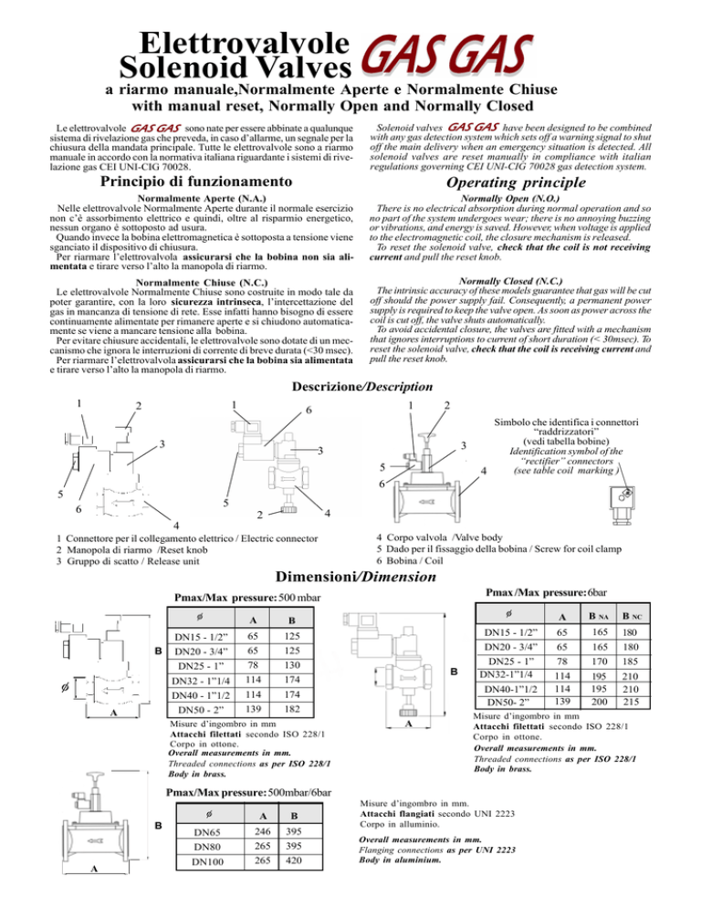
1 Connettore per il collegamento elettrico / Electric connector
2 Manopola di riarmo /Reset knob
3 Gruppo di scatto / Release unit
4 Corpo valvola /Valve body
5 Dado per il fissaggio della bobina / Screw for coil clamp
6 Bobina / Coil
Dimensioni/Dimension
Pmax /Max pressure: 6bar
Pmax/Max pressure: 500 mbar
φ
φ
A
DN15 - 1/2”
B DN20 - 3/4”
DN25 - 1”
DN32 - 1”1/4
DN40 - 1”1/2
DN50 - 2”
A
B
65
65
78
114
114
139
125
125
130
174
174
182
Misure d’ingombro in mm
Attacchi filettati secondo ISO 228/1
Corpo in ottone.
Overall measurements in mm.
Threaded connections as per ISO 228/1
Body in brass.
φ
B
DN15 - 1/2”
DN20 - 3/4”
DN25 - 1”
DN32-1”1/4
DN40-1”1/2
DN50- 2”
A
B
A
A
B
DN65
DN80
DN100
246
265
265
395
395
420
B NA
B NC
65
65
78
114
114
139
165
165
170
180
180
185
195
195
200
210
210
215
Misure d’ingombro in mm
Attacchi filettati secondo ISO 228/1
Corpo in ottone.
Overall measurements in mm.
Threaded connections as per ISO 228/1
Body in brass.
Pmax/Max pressure: 500mbar/6bar
φ
A
Misure d’ingombro in mm.
Attacchi flangiati secondo UNI 2223
Corpo in alluminio.
Overall measurements in mm.
Flanging connections as per UNI 2223
Body in aluminium.
Timbratura bobine/Coil marking
12Vdc
12Vca
24Vdc
24Vac
220Vac
N.A.
N.O.
12VDC 19W
12VAC 17VA
24VDC 19W
24VAC 17VA
220VAC 17VA
N.C.
12VDC 9W
12VRAC 12W
24VDC 9W
24VRAC 12W
220VRAC 12W
: a queste bobine deve essere associato un connettore particolare che funge da “ritardatore”e “raddrizzatore”, riconoscibile
dal simbolo posto su di essa.
Installazione e posizionamento
L’elettrovalvola dev’essere installata con la freccia stampata sul corpo rivolta verso l’utenza. Dev’essere posizionata a monte degli organi
di regolazione e preferibilmente all’esterno dell’ambiente in cui è presente l’utenza.
Posizione orizzontale
Horizontal position
Attacchi/Connection
: a particular connector must be associated to these coils which
acts as a “delayer” and “rectifier”. The connector is recognised by
the symbol carries on.
Installation and positioning
The solenoid valve must be positioned with the arrow stamped on the
body turned towards the user appliance. The valve must be positioned
upstream of the regulation apparatus and preferably outside the
measurement zone.
Posizione verticale
Vertical position
Posizione capovolta
Overturned position
NO
Da 1/2” a DN100
From 1/2” to DN 100
Manutenzione
Maintenance
Perdite di carico/Loss of head
∆p(mbar)
Si consiglia di verificare periodicamente l’intervento dell’elettrovalvola.
The solenoid valve’s intervention should be checked periodically.
In caso di necessità, prima di effettuare qualsiasi operazione
Should disassembly be necessary, make sure there is no gas under
sull’elettrovalvola, accertarsi che all’interno della stessa non ci sia gas
pressure inside the valve and that is not connected to the power supply
in pressione e che non sia alimentata elettricamente. Qualsiasi operabefore starting. All maintenance operations should be carried out by
zione di manutenzione dev’essere eseguita da personale qualifiqualified personnel.
cato.
DIAGRAMMA DELLE PERDITE DI CARICO/LOSS OF HEAD DIAGRAM
Metano/Methane CH4 (d=0,555)
Portata Q(Sm3h)
Delivery Q (Nm3/h)
Propano/Prophane C 3H8 (d=1,522)
Gas di citta’/Town gas (d=0,411)
Aria/Air (d=1)
CARATTERISTICHE TECNICHE/TECHNICAL CHARACTERISTICS
- Pressione max/Max pressure: 500mbar / 6bar (a seconda del modello/in according to the model)
- Tempo di chiusura/Closing time: < 1 sec.
- Potenza elettrica/Power capacity: tipo N.A./N.O.
12Vcc, 24Vcc
19W
12Vca, 24Vca, 230Vca
17VA
tipo N.C.
12Vcc, 24Vcc
9W
12Vca, 24Vca, 230Vca
12W
- Alimentazione elettrica/Power supply: 12Vcc, 12Vca, 24Vcc, 24Vca, 230Vca.
- Attacchi/Connections :da 1/2”a 2” filettati secondo ISO 228/1, da DN65 a DN100 flangiati secondo UNI 2223.
from 1/2” of 2” threaded as ISO 228/1, from DN65 of DN100 flanging as UNI 2223.
- Grado di protezione elettrica/Level of electrical protection: IP65.
- Temperatura di lavoro/Operating temperature: -15°C..... +70°C.
CEWAL S.p.A. Via Gramsci n°48, 30010 Camponogara (VE) - Italy
Tel. 041 462155 Fax 041 4174282
La società CEWAL S.p.A. si riserva il diritto di apportare qualsiasi modifica, estetica o funzionale, senza preavviso alcuno ed in qualsiasi momento.

