Dossena & C. S.n.c.
Manuale d’impiego
User’s manual
Dossena & C. di Barbati Agostino & C.
26824 Cavenago D’Adda (Lo) Via F.Barbarossa - Italy
Tel: +39.371.44971- Fax: +39.371.70202 - Email: [email protected]
Dispositivo per il controllo permanente dell’isolamento
Instrument to permanently keep insulation under control
Tipo-Type SRI / M
3
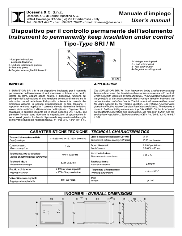
1- Led per indicazione
presenza tensione
2- Led per indicazione guasto
3- Pulsante prova
4- Regolazione soglia di intervento
1
4
2
1- Voltage warning led
2- Fault warning led
3- Test push-button
4- Regulation setting level
SRI/M
IMPIEGO
APPLICATION
Il SURVEYOR SRI / M è un dispositivo impiegato per il controllo
permanente dell’isolamento di reti monofase o trifase con neutro
isolato da terra, oppure senza neutro. Il dispositivo funziona sul
principio dell’applicazione di una tensione continua di misura tra la
rete sotto controllo e la terra. Il dispositivo misurerà la corrente che
l’impianto assorbe in seguito all’applicazione di tale tensione. Il
rapporto tensione applicata / corrente rilevata determina l’effettivo
valore della resistenza d’isolamento dell’impianto. L’apparecchio è
realizzato in custodia isolante da in casso secondo DIN 43700. Sul
pannello frontale sono riportate le segnalazioni di apparecchio in
servizio e di guasto, il pulsante di prova e la segnalazione della soglia
di intervento.(Norme di rispondenza CEI 41-1/66-3/12-13/64-8 / 11-1).
The SURVEYOR SRI / M is an instrument being used to permanently
keep under control the insulation of monophase networks with neutral,
which are earth insulated or without neutral. The instrument operates on
the prinsiple of the measurement direct voltage injection between the
network under control and earth. The intrument will measure the current
the plant absorbs by the voltage injection. The voltage / current ratio
gives the effective value of the plant insulation resistance. The devices is
made in built insulating case according DIN 43700. On the front panel
are located the operating and fault signals, the test push-button and the
setting level regulation. (Safety standards CEI 41-1 / 66-3 / 12-13 / 64-8 /
11-1).
CARATTERISTICHE TECNICHE - TECNICAL CHARACTERISTICS
Supply voltage
Max consumption
3 VA
400 V 50/60 Hz
Measurement voltage
IP 20
IP 50 per frontale
115-230-400 V+15 / -20% 50/60 Hz
24 Vc.c./d.c.
Insulation test
Measurement current max
2,5 KV per 60 sec.
2,5 KV for 60 sec.
25 µ A
Internal resistance
Tripping accuracy
Working temperature
Tripping valve adjustable
Weight
-10 ÷ + 55° C
gr. 300
SCHEMI D’INSERZIONE - WIRING DIAGRAMS
Schema di collegamento con neutro
Connection diagram with neutral
SRI/M
Schema di collegamento senza neutro
Connection diagram without neutral
14
15
SRI/M
Rete da controllare
Network to be controlled
11
12
13
115V
230V
400V
1
Rete da controllare
Network to be controlled
} Vaux
11
12
13
Alimentazione
Supply
L
19
17
18
0
E
T
115V
230V
400V
1
0
E
Fig. 3
} Vaux
Alimentazione
Supply
Segnalazione
Segnallings
L
19
17
18
Segnalazione
Segnallings
Fig. 2
14
15
T
Fig. 2 = Schema di collegamento per sistema trifase 400 V con neutro.
Fig. 3 = Schema di collegamento per sistema prifase 230 V L= Lampada:
segnalazione a distanza di guasto, (eventuale a cura del cliente). T=
Tromba: segnalazione acustica di guasto (eventuale a cura del cliente). E
= Commutatore asclusione tromba durante la ricerca guasto (eventuale a
cura del cliente).
Fig. 2 = Connecting diagram for 400 V 3-plase system with
neutral.
Fig. 3 = 230 V 3-plase system connecting diagram L = Lamp:
Fault remote signal (to be eventually provided by the client). T =
Horn: Fault audible signal (to be eventually provided by the client)
E = Horn: Shut-out commutator, during fault hunting (to be
eventually provided by the client)
MESSA IN SERVIZIO
OPERATING INSTRUCTIONS
Il SURVEYOR SRI/M è provvisto di morsetti ai quali vanno collegati i
conduttori secondo le indicazioni degli schemi (fig. 2-3). Fare attenzione
che non si verifichino spostamenti di fili e che le tensioni di alimentazione
abbiano il loro giusto valore. Dopo aver controllato che i collegamenti sono
corretti, alimentare il dispositivo; led “ON” si accenderà indicando la
presenza di tensione. Premendo il pulsante “Test” avverrà l’accensione del
led “TRIP”, rilasciando il pulsante il led “TRIP” si spegnerà
automaticamente, dopodichè impostare la soglia di intervento tramite la
regolazione posta sul frontale. Da questo momento il controllo
dell’isolamento può essere affidato al SURVEYOR SRI/M. Se la
resistenza d’isolamento scende sotto il valore impostato si illumina il led
“TRIP” e contemporaneamente si mette in funzione l’allarme acustico
esterno. L’operatore dopo aver tacitato l’allarme acustico (commutatore
E), potrà procedere alla ricerca del guasto. Una volta riparato si spegnerà il
led e riprenderà l’allarme acustico se il commutatore E è stato lasciato
nella posizione 1.
SURVEYOR SRI/M is fitted with clamps to which the leads have to
be connected according to diagram indications (fig. 2-3). Make
sure that no displacementof wires occurs and that supply voltages
have their correct value. Check that connections are properly
done, then energize the instrument: the lamp “ON” (rete) will light
up to warn of inserted voltage. By depressing the “TEST” (prova)
button, the lamp “fault” (guasto) turns on while by releasing it the
lamp turns out automatically. All this will prove that the instrument
is working regularly from this moment, surveying of insulation can
be enstrusted to the SURVEYOR SRI/M. Should insulation
resistance drop under stated value, the lamp “FAULT” turns on
simultaneously with tripping of the aural alarm. After having
silenced the aural alarm (commutator E) the operator can start
hunting the fault. Once the fault has been found and mended, the
lamp turns off while the aural alarm start again as long as
commutator E is left at position 1.
p
ANOMALIE DI FUNZIONAMENTO
OPERATING ANOMALIES
Non si accende il led ON: controllare la presenza di alimentazione
ausiliaria e verificare l’esatto collegamento delle connessioni.
The led ON doesn’t light up: control the auxiliary supply presence
and check the exact connections link.
Il sorvegliatore SRI/M non scatta al valore di resistenza impostato.
Premere il tasto “TEST”, se il led di “TRIP” si illumina il funzionamento del
sorvegliatore è corretto e di conseguenza l’anomalia va ricercata
sull’inserzione del sorvegliatore sulla rete da controllare. Nell’eventualità
che il “TRIP” non dovesse accendersi la si consideri come anomalia di
funzionamento dell’apparecchiatura.
The surveyor SRI/M doesn’t light up at the set resistance value:
press the TEST button, if the led of TRIP lightens, the sorveyor
working is correct and, consequently, the anomaly must be
searched on the surveyor inyection on the network to control. In
the event that of TRIP should not lighten, consider it like a working
anomaly of the instrument.
Segnalazione di “TRIP” accesa ma senza alcun intervento del relè:
staccare i collegamenti ai morsetti 17-18-19 e verificare, ad appa recchio
non alimentato, mediante ohmmetro, la continuità tra i morsetti 17-18.
Alimentare nuovamente il sorvegliatore, premere il pulsante di “TEST” e
verificare che la continuità sia ora tra i morsetti 17-19. In caso contrario è
da considerarsi come anomalia di funzionamento dell’apparecchio.
TRIP signal ON but without any tripping: take off the connections
at the clamps (terminals) 17-18-19 and chek, when the instrument
is unsupplied, by ohmmetro the continuity between the “clamps”
17 and 18. Supply again the surveyor, press TEST button and
check the continuity is now between the clamps 17 and 19. On the
contrary, you have to consider it like an instrument operating
anomaly.
N.B. : l’anomalia sopracitata si può anche verificare nei seguenti casi:
- Errata inserzione.
- Tensione o correnti differenti dalle specifiche dell’apparecchio.
- Elementi L, Eo T (fig. 2-3) in corto circuito.
N.B. : the above mentioned anomaly can appear also in the
fallowing cases:
-Wronginjection
-Voltage or currents different from the apparatus specifications.
- Elements L, E or T (fig. 2-3) in short circuit.


