Relaise 29/09/16
GENERATORE CICLICO
DI IMPULSI
GC 06
CYCLIC PULSE
GENERATOR
fino a 6 uscite, per carichi a 24 VAC
oppure 24VDC
up to 6 outputs, for 24VAC or 24VDC
loads
DEFINIZIONE
Il dispositivo attiva le uscite, in sequenza,
per il tempo T1 (impulso). Fra
l’eccitazione di 2 uscite intercorre il
tempo T2 (pausa). Dopo l’attivazione
dell’ultima uscita intercorre il tempo T3
(pausa fra cicli) poi viene eccitata
nuovamente la prima uscita.
FUNCTION
The device energizes the outputs in
sequence for the period T1 (pulse).
Between the excitation of two outputs
the period T2 takes place (pause). After
the last output has been activated, the
period T3 takes place (pause between
the cycles); then the first output is
energized again.
UTILIZZAZIONE
Per comando ciclico di vari carichi:
elettrovalvole per pulizia filtri, relè,
lampade,ecc.
USE
It is used for the cyclic command of
several loads, such as electrovalves for
cleaning filters, relays, lamps etc.
MODELLI
GC 06-6 per 6 uscite
GC 06-5 per 5 uscite
GC 06-4 per 4 uscite
GC 06-3 per 3 uscite
GC 06-2 per 2 uscite
Il numero delle uscite deve essere
definito all’atto dell’ordine.
MODELS
GC 06-6 for 6 outputs
GC 06-5 for 5 outputs
GC 06-4 for 4 outputs
GC 06-3 for 3 outputs
GC 06-2 for 2 outputs
The number of the outputs must be
declared at the order.
TECHNICAL FEATURES AND
REGULATIONS
CARATTERISTICHE
TECNICHE E REGOLAZIONI
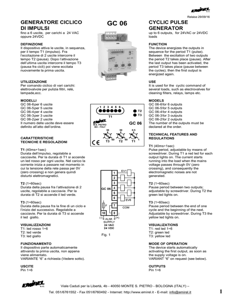
T1 (40ms÷1sec)
Durata dell’impulso, regolabile a
cacciavite. Per la durata di T1 si accende
un led rosso per ogni uscita. Nel carico la
corrente inizia a passare nel momento in
cui la tensione della rete passa per 0V
(zero crossing) e non genera quindi
disturbi elettromagnetici.
T1 (40ms÷1sec)
Pulse period, adjustable by means of
screwdriver. During T1 a red led for each
output lights on. The current starts
running into the load when the mains
voltage passes through 0V (zero
crossing), and consequently the
electromagnetic noises are not
generated.
T2 (1÷60sec)
Durata della pausa fra l’attivazione di 2
uscite, regolabile a cacciavie. Per la
durata di T2 si accende il led verde.
T2 (1÷60sec)
Pause period between two outputs;
adjustable by screwdriver. During T2 the
green led lights on.
T3 (1÷60sec)
Durata della pausa fra la fine di un ciclo e
l’inizio del successivo. Regolabile a
cacciavie. Per la durata di T3 si accende
il led giallo.
T3 (1÷60sec)
Pause period between the end of one
cycle and the beginning of the next.
Adjustable by screwdriver. During T3 the
yellow led lights on.
VISUALIZZAZIONI
T1: led rosso 1÷6
T2: led verde
T3: led giallo
VISUALIZATIONS
T1: red led 1÷6
T2: green led
T3: yellow led
Fig. 1
FUNZIONAMENTO
Il dispositivo parte automaticamente
attivando la prima uscita, non appena
viene alimentato.
VARIANTE “6” a richiesta (Vedere sotto).
MODE OF OPERATION
The device starts automatically
activating the first output, as soon as
the supply voltage is on.
VARIANT “6” on request (see below).
USCITE
Pin 1÷6
OUTPUTS
Pin 1÷6
Viale Caduti per la Libertà, 4b - 40050 MONTE S. PIETRO - BOLOGNA (ITALY) –
Tel. 051/6761552 - Fax 051/6760492 - Internet: http://www.emirel.it - E-mail: [email protected]
1
Per carichi 24 VAC: uscite a triac con
attivazione al passaggio per 0V della
tensione, con optoisolamento.
Per carichi 24 VDC: uscite a transistori
npn, con protezione a diodo.
pin 7: comune dei carichi; è internamente
collegato al pin 8, quindi è collegato ad
una fase, mentre nel caso di
alimentazione 24 VDC risulta collegato al
+ dell’alimentazione.
TENSIONE
CARICO
24 Vac
24 Vdc
CARICO
MAX
32 VA
32 W
CARICO
MIN
0,24 VA
----
INSTALLAZIONE E
COLLEGAMENTI ELETTRICI
Vedere fig.1.
(Collegamento a un quadro elettrico con
differenziale e sezionatore).
La lunghezza di ogni collegamento deve
essere < 30m.
ALIMENTAZIONE
24 Vac
protetta con fusibile 2A.
2VA - 50÷60 Hz ± 10%
pin 8-10
Nota generale: Negli schemi di
collegamento non sono riportati
i fusibili sulle alimentazioni e
sugli ingressi voltmetrici.
I collegamenti elettrici devono
essere eseguiti a dispositivo e
quadro elettrico spenti.
General remark: The wiring
diagrammes do not show the
fuses installed on the supply and
on the voltmetric inputs.
The electric wirings must be
realized
with
device
and
electrical panel in off condition.
COMPATIBILITA’ ELETTRO
MAGNETICA
Electromagnetic compatibility
CEI-EN 61326-1
24 Vdc
1 W protetta con fusibile 2A.
pin 8 (+) 10 (0V) 24Vdc ± 5%
For 24 VAC loads, the triac outputs
activate when the voltage passes
through 0V, with optoinsulation.
For 24 VDC loads npn transistors
outputs with diode protection.
pin 7: loads common; it is inside
connected to the pin 8, consequently it is
connected to one phase, while in case
of 24 VDC supply it is connected to + of
the supply.
LOAD
VOLTAGE
24 Vac
24 Vdc
MAX
LOAD
32 VA
32 W
MIN
LOAD
0,24 VA
----
INSTALLATION AND
WIRING DIAGRAMS
See fig.1.
(Wiring to an electrical board with a
differential relay and a sectionalizing
switch).
The lenght of every wiring must be less
than 30m.
SUPPLY
24 Vac
protected with fuse 2A
2VA - 50÷60 Hz ± 10%
pin 8-10
24 Vdc
1 W protected with fuse 2A
pin 8 (+) 10 (0V) 24Vdc ± 5%
In entrambi i casi, i carichi sono
alimentati dalla stessa tensione che
alimenta il GC 06.
In both cases the loads are supplied by
the same voltage supplying the device
GC 06.
CUSTODIA
53x90x75 mm per DIN - 3M
Accessorio a richiesta: pannello con
cerniera M 48C policarbonato trasparente
CASE
53x90x75 mm per DIN - 3M
Accessory on request: panel with hinges,
transparent polycarbonate M 48C.
TEMP. DI FUNZIONAMENTO: 0÷60°C
WORKING TEMPERATURE: 0÷60°C
PESO: kg 0,150
WEIGHT: kg 0,150
COLORE: grigio
Nota generale: Negli schemi di
collegamento non sono riportati i fusibili
sulle alimentazioni e sugli ingressi
voltmetrici.
I collegamenti elettrici devono essere
eseguiti a dispositivo e quadro elettrico
spenti.
VARIANTE “6”
Il dispositivo parte automaticamente,
attivando la prima uscita 30 secondi
dopo che è stato alimentato.
Per la pulizia usare un panno imbevuto di
detergenti privi di: Alcool denaturato,
Benzene, Alcool isopropilico.
COLOUR: grey
General remark: The wiring
diagrammes do not show the fuses
installed on the supply and on the
voltmetric inputs.
The electric wirings must be realized
with device and electrical panel in off
condition.
VARIANT “6”
The device starts automatically
activating the first output, 30 seconds
after the supply voltage is on.
For cleaning use a cloth soaked with
detergents without: Denatured Alcohol,
Benzene, Isopropyl alcohol.
Viale Caduti per la Libertà, 4b - 40050 MONTE S. PIETRO - BOLOGNA (ITALY) –
2
Tel. 051/6761552 - Fax 051/6760492 - Internet: http://www.emirel.it - E-mail: [email protected]

